FROM CLEAN TO EXTREME
Congratulations and thank you for purchasing the LA 25 MKII. This Amplifier was designed
to inspire you and elevate your playing all the way to the highest level. We really took the
long road on designing the LA 25 MKII because repeating ourselves was not an option.
We decided to take on the challenge and break a new ground. First of all we went for the
world wide renowned clean and functional Swedish design, using only the highest quality
components and materials available on the market today. Second we went for making it
logical and easy to operate and really improve both tactical and visual ergonomics for fast
operation and visibility of functions even in the dark. We are very proud to have achieved
building a power house amp under 7.8 Kg with it’s small physical footprint making it
possible to bring as a hand luggage on an airplane.
We also engineered everything in a 19“ Rack 3U format with only 17 cm depth. It can work
in any situation since you can put it in a studio rack, touring rack or even in a wooden headshell
if you would like to have that classic look of an amplifier. We packed it full with so many
features, some never done before like: a built in Re-Amplifier, a DI, a Virtual Mic speaker
simulator and a reactive load in one amp. You can use the LA25 MKII without any speaker
or an external load. The possibilities are limitless.
The original LA 25 has its own signature sound slightly darker and softer with just a slight
touch smoother top end in the Crunch and Vintage modes.The choices we made to alter the
core DNA of the LA 25 MKII resulted in a new brighter sonic palette and quite alot more gain.
As any other of our devices , this one requires very little care and just a little bit of attention to our
recommendations regarding maintenance. Please spend a couple of minutes to read this manual so
you can get the most out of the product. Remember and implement these few recommendations
for handling the product and you will be able to operate it for many years to come.
We hope you’ll enjoy this product
just as much as we enjoyed designing and making it
SAFETY INFORMATION
- Pollution Degree 2
- Maximum Relative Humidity: <80%
- Operation temperature range: 10 °C to 35 °C
- Ordinary Protection: This equipment should
not be exposed to dripping or splashing.
- Avoid placing objects filled with liquids,
such as vases or glasses, on this equipment.
- Storage and transportation temperature
range –25 °C to 45 °C
- Equipment suitable for continuous operation
This product complies with the
(2012/19/EU) WEEE Directive. The affixed
product label indicates that you must not
discard this electrical/electronic
product in domestic household waste.
No user serviceable parts inside Refer
all servicing to qualified service personnel.
By affixing the CE marking to a product,
a manufacturer declares that the product
meets all the legal requirements for CE
marking and can be sold throughout the EEA.
Keep away from rain or moisture.
No dripping or splashing.
No objects filled with liquids
should be placed on or near the product.
Read and follow these instructions of proper usage
Before going any further, make sure that your amplifier
is compatible with your mains electricity supply.
The (a) voltage selector must be set to match the local
power grid. The (c) fuse must match the local power
grid and the (a) voltage selector. Check what is written
in the field (d). If it matches the local power grid, you
are good to go. If it doesn’t match, the mains fuse has
to be changed.
Mains input & fuse: The specific mains input voltage
rating that your amplifier has been manufactured for
is indicated on the rear panel of the amplifier. Your
amplifier is provided with a detachable mains (power)
lead, which should be connected to the (b) mains
input socket on the rear panel of the amplifier. The
correct value and type of mains fuse is specified on
the rear panel of each amplifier. NEVER attempt to
bypass the fuse or fit one of the incorrect value or
type.
Changing the mains fuse: Make sure that the mains power lead is unplugged; Make sure that the
(21) voltage selector is set properly; Open the (23) mains fuse socket lid; Replace the fuse; Close the lid.
Transporting your equipment: Please ensure that your amplifier is switched off, unplugged from
the mains electricity supply and that all removable cables have been disconnected from your
equipment before attempting to move it. Keep the original box in case of shipping the amp to us
for repair or replacement.
Important set up information: Failure to select the correct impedance may damage your
amplifier. If connecting a speaker cabinet make sure that you use a proper speaker cable. Never
use a screened (shielded) guitar cable for this purpose.
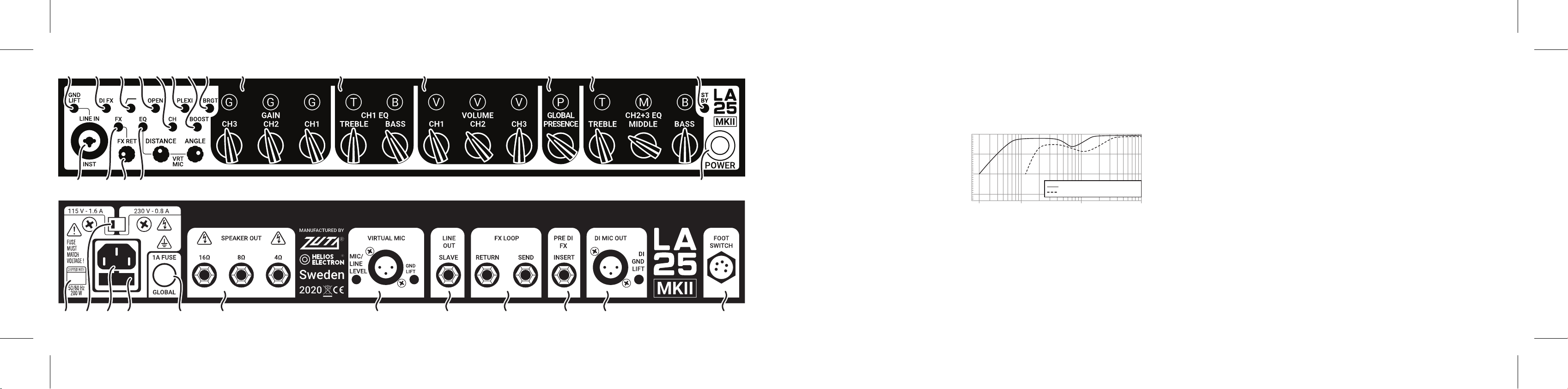
a. Voltage selector switch
b. Mains input socket
c. Mains fuse socket
d. Mains fuse info label
e. Global fuse
acbd