2
TECHNICAL DATA
Before proceeding to assembly,
please make sure all the
following conditions are veried
• Max. water pressure endured: 6 bar
• Recommended ow rate: 12,5L/min
• Maximum ow rate: 25,0 L/min
• Max. water temperature: 60ºC
• Min. height clearance: 90mm
INSTALLATION INSTRUCTIONS
Zypho® S|im Heat Exchangers are provided
as a complete bundle.
Please check the content of the package for
completeness and integrity before proceeding.
Should any deviations be noted, please consult your
supplier and do not start the assembly. You must never
alter or modify the provided components by Zypho®. For
a proper installation, please use these components only.
Before the freshwater connection a non-return valve and
a shut-o valve should be installed (type EA).
We recommend the use of a thermostatic shower mixer.
NON-COMPLIANCE WITH THESE RECOMMENDATIONS
FOR INSTALLATION AND USE MAY VOID ANY WARRAN-
TY.
SAFETY
Zypho® S|im Heat Exchangers are double walled,
according to European regulation EN 1717 (“Protection
against pollution of potable water in water installa-
tions and general requirements of devices to prevent
pollution”).
We test all Zypho® units in our factory before shipping.
The main water circuit is pressurized up to 9 bar to ensu-
re that there are no leaks or defects.
MAINTENANCE
Zypho® S|im Heat Exchangers have been designed to
require minimal maintenance eorts.
They must be installed with the shower drain provided.
Periodic cleaning is recommended to optimise energy
exchange. Use a non-corrosive drain cleaner or a water
jet. We recommend our water jet brush ZYMN00000J1.
IMPORTANT REMARKS
INSTALLATION
The preheated water supply inline of the ZYPHO S|im
must be insulated in accordance with the requirements
of the ‘Building Services Compliance Guide’.
Pipework between the WWHRS preheated water outlet
and the water heater and /or shower cold water inlet(s)
(depending on installation conguration) must be
labelled to indicate that no other services can be inter-
connected.
System A: Installation conguration 1
System B: Installation conguration 2
System C: Installation conguration 3
Energy Saving Performance Recognised by SAP
The successful operation of the ZYPHO S|im which is a
Waste Water Heat Recovery System (WWHRS) – Instan-
taneous Shower Heat Recovery Device, depends entirely
upon the adherence to these instructions. Additionally,
for new-build dwellings within the UK, recognition of the
system’s energy saving performance within the National
Calculation Methodology (NCM) for the energy rating of
dwellings, known as the Standard Assessment Proce-
dure (SAP) requires that these instructions are complied
with in conjunction with a system design checklist and an
installation checklist and certicate of installation,
supplied with this document and available at:
www.ncm-pcdb.org.uk/sap.
The system should be installed by a suitably qualied
plumber, with system design consideration being equally
important to a correct installation. For recognition of the
ZYPHO S|im within SAP, a system design checklist and
an installation checklist and certicate of installation
should be completed and signed, with copies kept for the
home user pack (home owner), the installer, and sent
to ZYPHO at the post or e-mail address shown below.
Building Control Ocers may also request a copy. For the
purpose of system identication of product data without
SAP, the product will have an NCM (SAP) Identier label
permanently xed to the unit, whereby the ‘model qua-
lier’ states ‘refer to installation certicate, if unknown
assume System B’. A second NCM (SAP) Identier label
is also supplied and must be axed to a nearby boiler or
service cupboard (the label must be visible for inspec-
tion without disassembly of nearby products or
systems) and the ‘model qualier’ states ‘System A,
System B or System C delete as appropriate’.
Not sending back the completed and signed system
design checklist, the installation checklist and certicate
of installation to ZYPHO will invalidate the guarantee.
Address
Rua Barão do Corvo, 37 – 1°F
4400-039 V N Gaia, PORTUGAL
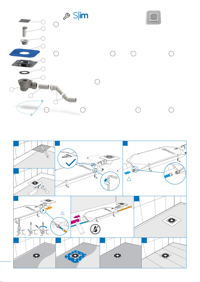
COMPONENTS AND DIMENSIONS P. 9
INSTALLATION CONFIGURATION OPTIONS P. 8 INSTALLATION GUIDE P. 10,13