18 19
Hardware: Installation
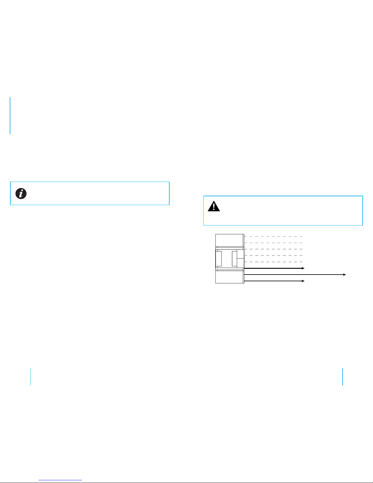
Emergency Lights & Manual Activation
Therearefour(4)wires(leads)comingfromthesensorharness.Eachwire
willactivatetherecorderwhenvoltageisappliedtoanysinglewire.Ina
typicalpatrolcarinstallation,2ofthesewireswillbeused.
Sensor 1 - to pursuit lights
Sensor 2 - to manual switch
Sensor 3 - to brown wire of 2.4Ghz Mic
FIG. 2
Sensor Harness
These wires will detect when voltage is present and activate the
recorder.
Sensor ‘IN’ Wire 1
1 ConnectSensorWire1totheoutputsideofyourcontrolboxforyour
pursuitlights.
Youcanconnectittoanyofthelightsthatareusedforemergency
trac.Thiswaytherecorderwillstartanytimeyouarerunning
emergencytrac.Dependingonthetypeofswitchboxused,there
maybeaplacetoconnectatthebackoftheswitchbox.Ifnot,simply
connecttoanywirethatgoestoa12vlightthatisactivatedwhenyou
turnontheemergency/pursuitlights.
Sensor ‘IN’ Wire 2
2 ConnectSensorWire2toamanualswitchthatyouwillactivatewhen
youwanttostarttherecorderwithoutlightsactivated.
Youcanuseanyswitchofyourchoosingthatwillprovide12vtothe
wire.
Manycontrolboxesinusetodaywillhaveablankswitchthatisnot
beingused.Theseareagreatchoiceforthemanualswitch.Ifnoneare
available,asimpletoggleorrockerswitchmountedinaconvenient
locationworkswell.
Caution: These wires are very sensitive and care must be
taken that you do not connect to a wire that has low voltage all
the time, as the recorder will detect voltage and activate the
recorder.
Emergency Lights & Manual Activation Installation