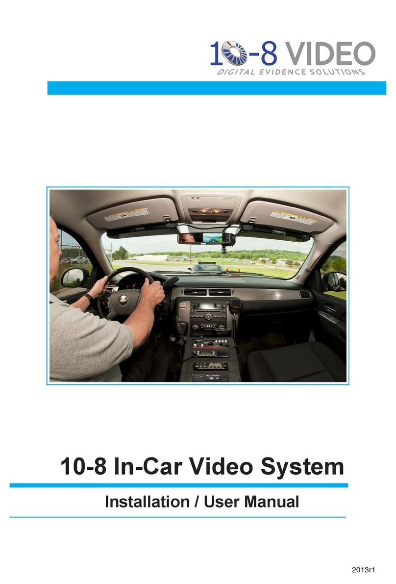
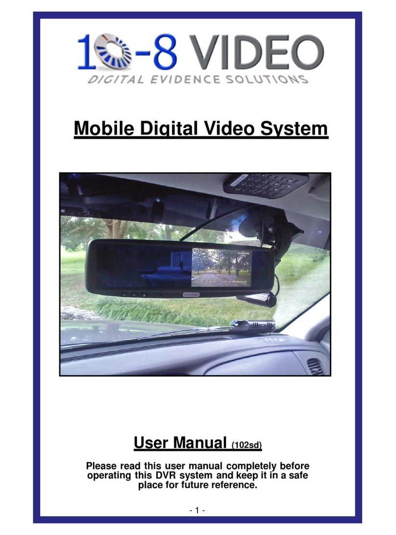
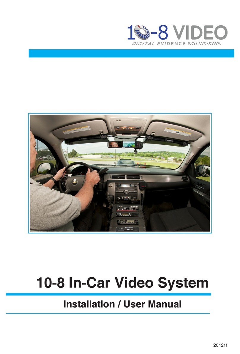
10-8 Video Digital Evidence Solutions In-Car Video System Instruction Manual

2013r2
Installation / User Manual
10-8 In-Car Video System

2
Copyright © 2011-2013 10-8 Video Digital Evidence Solutions. • All rights reserved.
Disclaimer: 10-8 Video Digital Evidence Solutions reserves the right to make changes in
specications at any time and without notice. The information provided by this document
is believed to be accurate and reliable. However, no responsibility is assumed by 10-8 Video
Digital Evidence Solutions for its use; nor any infringements of patents or other rights of
third parties resulting from its use. No license is granted under any patents or patent rights
of 10-8 Video Digital Evidence Solutions.
Other company and product names mentioned herein may be trademarks of their respective
companies.
10-8 Digital Video Evidence Solutions
1423 Huntsville Hwy.
Fayeeville, TN 37334
Tel: (888) 788-1048 • (931) 262-2221
Fax: (931) 233-1263
World Wide Web: www.10-8Video.com

3
Warranty & Return Information
All Products
• Three (3) year free replacement of any failed component. No RMA
required.
Car Camera Components
1. Call 1-888-788-1048 and ask for Technical Support or request
replacement parts via our website at:
hp://www.10-8video.com/warranty-form.php
2. We will then mail a new component via USPS Priority Mail within
one (1) business day.
3. When you receive the replacement, mail back the failed component.
Shipping Address
10-8 Video Digital Evidence Solutions
1423 Huntsville Hwy.
Fayeeville, TN 37334
Phone Numbers
(888) 788-1048 • (931) 262-2221
(931) 233-1263 (FAX)

4
Contents
CD-ROM Instructions 9
Manuals 9
Safety 10
Installation Safety 10
Daily Operation 11
Package Contents 12
System Schematic 14
Hardware: Installation 15
Introduction 15
Digital Video Recorder Unit (DVR) 16
Common Installation Areas 16
Emergency Lights & Manual Activation 18
2.4GHZ Wireless Mic 20
2.4 Ghz Wireless Mic DVR Set-up 21
Black Wire (Audio Out) 21
2.4GHZ Mic Antenna 23
UHF Wireless Mic 24
Single System Setup 26
Automatic Frequency Selection 26
Automatic Transmitter Setup 27
UHF Transmitter 28
Wearing the Bodypack Transmitter 29
Changing the Bodypack Transmitter Batteries 29
Mirror Monitor 30
Camera Mount 32
Front Camera 34
Rear Camera 36
G-Force Sensor 37

5
GPS System 37
Setting the GPS Speed Trigger 37
Hardware: Configuration 38
DVR Conguration 38
Entering Your Information 38
2nd Camera Conguration 39
Setting Date and Time 40
G-Force Sensor Conguration 41
Hardware: Usage 42
In-Car Playback 42
Watch Previously Recorded Events 42
Viewing Today’s Recordings 42
Viewing Another Day’s Recordings 43
Stopping Playback 43
DVR Remote Control 44
Selecting Camera 44
Entering Your Unit/Car ID 44
Camera Adjustment 45
Wireless Mic – 2.4GHZ 46
Syncing Transmitter and Cradle 46
Transmitting Audio 46
Mode Button 47
Microphone 47
Wireless Mic - UHF 48
Microphone 48
Software: Installation 49
Software Installation 49

6ContentsContents
Contents
Software: Introduction 50
Software Overview 50
Software: Usage 52
Opening A File 52
Searching For A File 53
Playing A File 54
Adjusting Playback Speed 54
Adjusting Playback Volume 54
Maximizing the View of a Video Clip 54
Stopping Playback 55
Monitoring G-Force and Speed Events 55
Using the Google™GPS Window 56
Saving a Snapshot 56
Exporting Events to a Video File 57
Maintaining Evidence Integrity 57
Exported File Format 57
Steps to Export Video 57
Video Export Options 57
Exporting an Event Report 59
Software Settings 60
System Parameters 60
Map Parameters 60
Video Parameters 60
File Associations 61
Archiving Video Tips 62
Appendix A 64
GMT Time Zones - United States 64

7
ContentsContents
This page left intentionally blank.

8
CD-ROM
CD-ROM

9
When you insert the CD it will automatically run the software
installation program
CD-ROM Instructions
CD-ROM
The CD at left contains the viewer software needed for playback on your
computer. It also includes PDF copies of all manuals.
Manuals
To access the manuals:
1 Insert the CD into your CD-ROM/DVD drive.
2 When the installation program launches, click Cancel at the install
prompt.
3 You can then access the les on the CD through your le manager like
you would any other CD.

10
1. Handle all components with care. Inspect regularly for damage to
components and cabling.
2. You are responsible to ensure that the installation of this product does
not void or aect the vehicle manufacturer’s warranty.
3. Do not apply excessive force to any of the components contained
within this kit.
4. Please follow the procedures from this installation manual.
Safety
Installation Safety
WARNING: This product utilizes high voltage. Any
unauthorized modications or damage to the products may
result in electrical shock.
10-8 Video, or its branches are not liable in full or in part for
improper installation resulting in loss or damage to your property,
or for voiding all or part of the vehicle manufacturer’s warranty.
Excessive force used before, during or after installation that
results in a damaged or non-functional part shall void all
warranties.
Improper installation or modication of this product shall void all
warranties.
Safety
11
Daily Operation
You, as the driver, are solely responsible for the safe operation of your
vehicle and the safety of your passengers according to the US and local
trac regulations.
10-8 Video cannot accept any responsibility whatsoever for accidents
resulting from failure to observe these precautions or safety instructions.
WARNING: Do not use any features of this system to the
extent it distracts you from safe driving. Your rst priority
while driving should always be the safe operation of your
vehicle.
Safety

12
Package Contents
Camera* & Mount Digital Video Recorder (DVR)
Mirror Wireless Mic (Optional)
2.4GHZ model shown.
GPS Unit (Optional)
REC ALM SD1
PWR GPS SD2
IR
* NOTE: Actual camera appearance may vary
from illustration.

13
HARNESSES (Simplified for clairity)
Power Harness
Sensor Harness
Mirror Harness
Camera Harness
A/V Harness
2.4GHZ Harness
Video Harness

14
System Schematic
GPS
Fuse
RED:
Vehicle +12V “Ignition on”
BLACK:
Vehicle Chassis Ground
Green Wire of 2.4Mhz Mic
to manual activation switch
to pursuit lights
Blue Wire of 2.4Mhz Mic Sensor 2 Out
Sensor 1 Out
Sensor 1 In
Sensor 2 In
Sensor 3 In
4 Pin
A/V
Harness
6 Pin
Power
Harness
CAT 5
GPS
BLACK (PWR GND)
to ground
RED (PWR)
to Constant
+12V Supply
NOTE: Actual camera appearance may vary from illustration.

15
Hardware: Installation
Introduction
The installation of the 10-8 Patrol Car video system breaks down to some
very simple steps. The basic connection for video and audio are very similar
to a VCR or DVD player. The one area that diers from what you may have
done in the past is the connections for the alarm inputs . There are four (4)
sensor wires that will activate the recorder anytime voltage is applied to any
of the four (4) wires.
To help make the connections easier, the cables that aach to the back of
the DVR each use a dierent type of connector. Familiarize yourself with
the inputs in the picture on pages 12 and 13.
You will need two 12 volt power sources - a constant 12 volt
power source and a switched 12 volt power source.
You will also need a ground source.
We strongly recommend that the power source be from switched power
that is only hot when the vehicle key is in the ‘ON’ position. This should be
a ve (5) amp fused power source. To eliminate interference, there should
be no other equipment on this circuit.
It is also very important that the ground be a good chassis
ground source and not tied into the ground of other equipment.
When the DVR’s door is unlocked to allow access to the SD
cards, the system is automatically powered down to protect the
les on the SD cards. When the door is locked, the DVR system
will be able to accept power and turn on again.

16
Hardware: Installation
DVR Installation
Digital Video Recorder Unit (DVR)
The rst thing you will want to do is locate where you want to install the
DVR. The small size of the unit makes that much easier than just a few short
years ago.
Common Installation Areas
• Main equipment console
• Either side of the console
• In the dash
• Under the dash.
• Under pr next to Main Equipment Console
• For Havis consoles, Havis oers a one piece mounting bracket.
Part# C-E-T8V-1P
• For Joo consoles, Joo oers a mounting bracket. Part# 425-6293
1 Insert the Red/Black 6-pin Power Harness Connector into power
receptacle in rear of DVR unit making sure it locks into place.
2 Connect BLACK lead to a chassis ground.
3 Connect RED lead to 12 volt ‘ignition on’ power source.
4 Connect Sensor Harness to back of DVR.
5 Connect 4-pin A/V Harness to back of DVR.
6 Connect GPS Cable Connector to back of DVR.
7 Connect Camera Harness to back of DVR. Tighten connector nut to
secure harness.

17
DVR Installation
GPS
RED: Vehicle +12 v “Ignition on”
BLACK: Vehicle Chassis Ground
4 Pin
AV Harness
GPS
6 Pin
Power Harness Camera
Harness
Sensor
Harness
GPS
FIG. 1
Connecting Harnesses to DVR
1
4
567
Try to keep the unit in sight of the driver where they will be able
to use the I/R remote more easily. If needed, the DVR ships with
brackets for mounting.

18
Hardware: Installation
Emergency Lights & Manual Activation
There are four (4) wires (leads) coming from the sensor harness. Each wire
will activate the recorder when voltage is applied to any single wire. In a
typical patrol car installation, 2 of these wires will be used.
These wires will detect when voltage is present and activate the
recorder.
Emergency Lights & Manual Activation Installation
Sensor ‘IN’ Wire 1
1 Connect Sensor Wire 1 to the output side of your control box for your
pursuit lights.
You can connect it to any of the lights that are used for emergency
trac. This way the recorder will start anytime you are running
emergency trac. Depending on the type of switch box used, there
may be a place to connect at the back of the switch box. If not, simply
connect to any wire that goes to a 12v light that is activated when you
turn on the emergency/pursuit lights.
Sensor ‘IN’ Wire 2
2 Connect Sensor Wire 2 to a manual switch that you will activate when
you want to start the recorder without lights activated.
You can use any switch of your choosing that will provide 12v to the
wire.
Many control boxes in use today will have a blank switch that is not
being used. These are a great choice for the manual switch. If none are
available, a simple toggle or rocker switch mounted in a convenient
location works well.

19
Sensor Out 1 (Not Used)
Sensor Out 2 (Blue Wire) - to blue wire of 2.4 Mhz Mic
Sensor In 1 - to pursuit lights
Sensor In 2 - to manual activation switch
Sensor In 3 (Green Wire) - to green wire of 2.4Ghz Mic
FIG. 2
Sensor Harness
Caution: These wires are very sensitive and care must be
taken that you do not connect to a wire that has low voltage all
the time, as the recorder will detect voltage and activate the
recorder.
Emergency Lights & Manual Activation Installation

20
Hardware: Installation
2.4GHZ Wireless Mic
If your department opted for our new 2.4ghz wireless microphone system,
congratulations! This is an incredible wireless microphone with excellent
range and clarity. The installation is easy and straight forward.
1 Find a suitable place in the vehicle for the base station/receiver.
A bracket is included. It should be mounted in an easily accessible
position. Be sure there is room to easily insert and remove the
transmier in the cradle.
2 Connect the harness BLUE wire - labeled ‘12v input rec’ - to the DVR
BLUE wire labeled ‘Alarm out 2’.
3 Connect the harness GREEN wire - labeled ‘Trigger’ - to the DVR
GREEN wire labeled ‘Alarm In 3’.
4 Congure the DVR software using the instructions on the next page.
2.4GHZ Wireless Mic Installation
Power to the charging cradle should be connected to a 12v
source that is always on. The rest of the system should be
connected to a ‘key on’ 12v source. This allows the transmitter
to charge fully between shifts.
Other manuals for In-Car Video System
2
This manual suits for next models
1
Table of contents
Other 10-8 Video Digital Evidence Solutions Car Video System manuals

10-8 Video Digital Evidence Solutions
10-8 Video Digital Evidence Solutions In-Car Video System Operation manual

10-8 Video Digital Evidence Solutions
10-8 Video Digital Evidence Solutions In-Car Video System Instruction Manual

10-8 Video Digital Evidence Solutions
10-8 Video Digital Evidence Solutions 102sd User manual