manuals.online logo
Brands
  1. Home
  2. •
  3. Brands
  4. •
  5. 2Y-LINK
  6. •
  7. Signal Processor
  8. •
  9. 2Y-LINK CI04-ASP User manual

2Y-LINK CI04-ASP User manual

Popular Signal Processor manuals by other brands

Korg A4 Guitar owner's manual

Korg

Korg A4 Guitar owner's manual

Omron K3TX Operation manual

Omron

Omron K3TX Operation manual

Anritsu MX371054A Operation manual

Anritsu

Anritsu MX371054A Operation manual

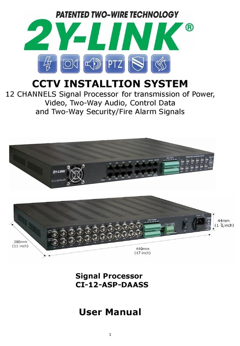
2Y-LINK Technology CI-12-ASP-DAASS user manual

2Y-LINK Technology

2Y-LINK Technology CI-12-ASP-DAASS user manual

Steg DSP 6 owner's manual

Steg

Steg DSP 6 owner's manual

Rocktron INTELLIFEX LTD user manual

Rocktron

Rocktron INTELLIFEX LTD user manual

Crane Song Falcon Operator's manual

Crane Song

Crane Song Falcon Operator's manual

RF-Lambda RF1457 instructions

RF-Lambda

RF-Lambda RF1457 instructions

TC Electronic DB8 MKII Hardware installation guide

TC Electronic

TC Electronic DB8 MKII Hardware installation guide

Texas Instruments TMS320VC5501 Instruction Cache

Texas Instruments

Texas Instruments TMS320VC5501 Instruction Cache

PCI MicroTrans EQ Operation & maintenance manual

PCI

PCI MicroTrans EQ Operation & maintenance manual

Oberheim GM-1000 operating manual

Oberheim

Oberheim GM-1000 operating manual

Tektronix TMS 702 instruction manual

Tektronix

Tektronix TMS 702 instruction manual

Vega VEGAMET 624 Supplementary instructions

Vega

Vega VEGAMET 624 Supplementary instructions

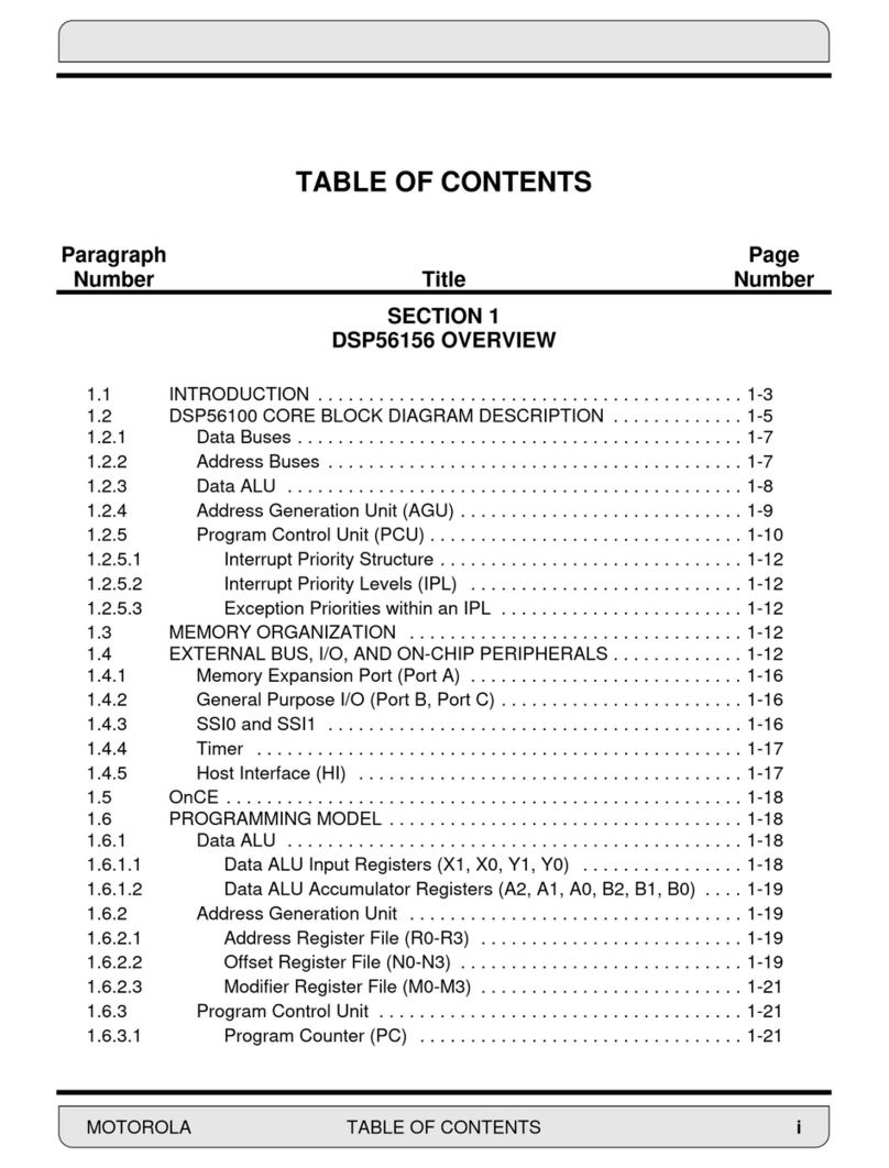
Motorola DSP56156 manual

Motorola

Motorola DSP56156 manual

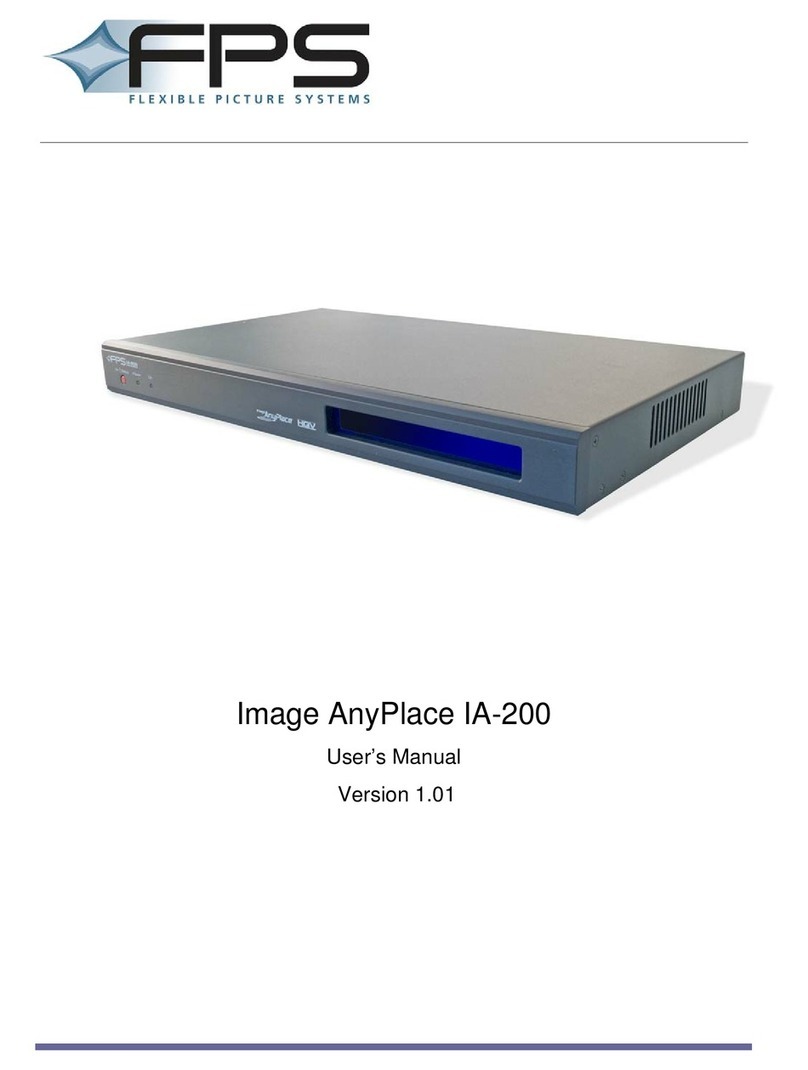
FPS Image AnyPlace IA-200 user manual

FPS

FPS Image AnyPlace IA-200 user manual

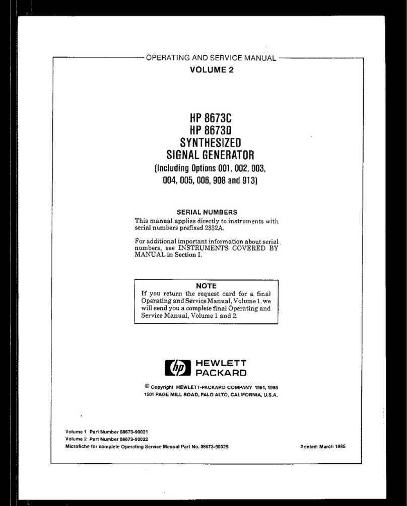
HP HP 8673C Operating and service manual

HP

HP HP 8673C Operating and service manual

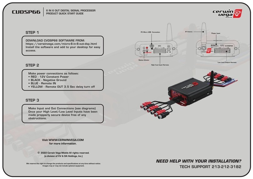
Cerwin-Vega CVDSP66 quick start guide

Cerwin-Vega

Cerwin-Vega CVDSP66 quick start guide

manuals.online logo
manuals.online logoBrands
  • About & Mission
  • Contact us
  • Privacy Policy
  • Terms and Conditions

Copyright 2025 Manuals.Online. All Rights Reserved.

DIP Switch setting : (ON – “1”, OFF – “0” )
1
2
3
4
LOW 0 0 0 0
1 0 0 0
1 1 0 0
1 1 1 0
HIGH 1 1 1 1
Choose the best combination of DIP switch setting for good picture
quality. Picture quality may be affected by several factors, such as wire
gauge, length of cable, camera, environment…etc.
 For camera power over 8W (12VDC, 680mA) and/or covering
extended distances, local Linear P/S Adaptor for camera is required.

UC-ISO Ground Loop Isolator may be required to
eliminate electrical noise and hum if using
Switching Mode P/S Adaptor
Video output 1Vp-p 75-ohm
Power Supply 48VDC
Operating temperature -10°C ~ + 50°C
Dimensions 145mm x 80mm x 33mm
Suitable for any Camera with following specification:
Each Camera Rating : 12VDC, 680mA. Max.
Each Camera Video output : 1Vp-p 75-ohm
Specification of CI04-ASP
Color/Brightness Switch adjustment
DIP NO.
Color/Brightness
Ascending Level
Local Power for Camera
4
2Y-LINK
Advanced Universal CCTV Signal Processor
User Guide
 Does not require coaxial cable
 Wired with only one two-wire bell cable to transmit both video signal
& power
 Simple and easy Installation
1: 4 BNC ale plug 2: 8 two-wire ter inal
3: DC socket 4: Power LED indicator
5: Color/Brightness Switch
User
Guide
eatures
Overview
4
-
CHANNEL
SIGNAL P
ROCESSOR
CI04
-
A
SP
1
Connect with CI04-ASP as shown in this diagram:
Connection Diagram
UC
-
M
X12V
1. DC plug 2. BNC ale plug
UC-AMIX-2A,
UC-AMIX-2B,
UC-AMIX-2C.
(See Mixer Selection Note on page 3)
2
Connect to
Signal Processor
(CI04-ASP)
UC-AMIX-2A Advanced Universal Mixer (up to 500m)
UC-AMIX-2B Advanced Universal Mixer (500m to 1000m)
UC-AMIX-2C Advanced Universal Mixer (1000m to 1500m)
•The following table shows the necessary wire gauge for twin bell wire
over the expected length between camera and TV Monitor.
150 A /2W 250 A/3W
UC-AMIX-2A
UC-AMIX-2B
UC-AMIX-2A
UC-AMIX-2B
AWG20
≤500m 500~1000m
≤500m 500~1000m
CAT5 ≤500m 500~700m ≤500m
350 A/4W 500 A /6W
UC-AMIX-2A
UC-AMIX-2B
UC-AMIX-2A
UC-AMIX-2B
AWG20
≤500m 500~800m ≤500m
CAT5 ≤400m ≤200m
680 A/8W Local Power for Ca era
(see Note on page 4)
UC-AMIX-2A
UC-AMIX-2A
UC-AMIX-2B
UC-AMIX-2C
AWG20
≤200m ≤500m 500~1000m
1000~1300m
CAT5 ≤100m ≤500m 500~1000m
1000~1500m
Mixer Selection
Wiring Notes
3