COM
•In communications engineering
the gain or attenuation of a signal
is specified in decibels as the log-
arithm of the ratio between the
measured voltage and a defined
reference voltage. Positive values
correspond to a gain and negative
values reflect attenuation. The ref-
erence voltage of the multimeter
amounts to 0.775 V (= 1 mW at
600 Ω). With this voltage there is
a gain of 0 dB.
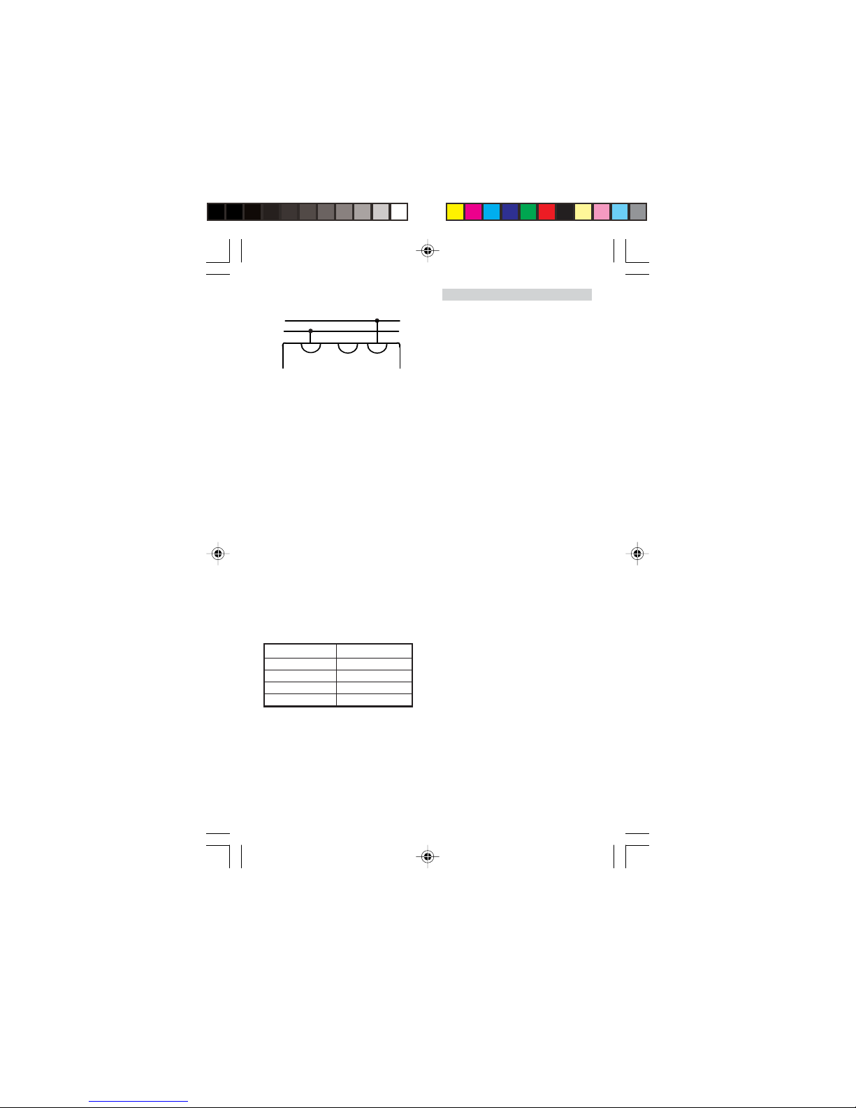
•Using the rotary switch (1) select
the corresponding measurement
range “600,..., 10 V AC”.
•Connect the multimeter and take
a reading on the dB scale.
•Since this scale is only valid for the
10 V measurement range, in the
other measurement ranges a rela-
tive constant must be added to the
value obtained from the scale:
Meas. range Constants
30 V 10 dB
100 V 20 dB
300 VB 30 dB
600 V 36 dB
4 Maintenance
4.1 Cleaning
•Only use a paintbrush or soft tow-
el to clean the multimeter. If stat-
ic electrical charging occurs on the
view window this can be eliminat-
ed using a damp rag or an anti-
static agent.
4.2 Battery
•Test the battery from time to time.
If it is dead or it has started to de-
compose, it must be removed from
the device. The battery is replaced
in accordance with 3.1.
•If the multimeter remains idle
over a long period of time, the
battery should be removed from
the unit.
4.3 Replacing the fuse
•The multimeter is equipped with
a safety fuse F3,15 A/500 V. To re-
place the fuse the device must be
opened as described in section 3.1.
Remove the fuse and replace it
with a fuse of identical type. Then
replace the section of housing and
snap it back into place securely.
3B Scientific GmbH • Rudorffweg 8 • 21031 Hamburg • Germany • www.3bscientific.com • Technical amendments are possible