3Com NETBuilder II FDDILink Instruction Manual

http://www.3com.com/
®
Installing the NETBuilder II
®
FDDILink
™
Module
Part No. 09-1064-000
Published May 1997

3Com Corporation
5400 Bayfront Plaza
Santa Clara, California
95052-8145
Copyright ©
3Com Corporation, 1997.
All rights reserved. No part of this documentation may be
reproduced in any form or by any means or used to make any derivative work (such as translation,
transformation, or adaptation) without permission from 3Com Corporation.
3Com Corporation reserves the right to revise this documentation and to make changes in content from
time to time without obligation on the part of 3Com Corporation to provide notification of such revision
or change.
3Com Corporation provides this documentation without warranty of any kind, either implied or
expressed, including, but not limited to, the implied warranties of merchantability and fitness for a
particular purpose. 3Com may make improvements or changes in the product(s) and/or the program(s)
described in this documentation at any time.
UNITED STATES GOVERNMENT LEGENDS:
If you are a United States government agency, then this documentation and the software described
herein are provided to you subject to the following restricted rights:
For units of the Department of Defense:
Restricted Rights Legend:
Use, duplication, or disclosure by the Government is subject to restrictions as
set forth in subparagraph (c) (1) (ii) for Restricted Rights in Technical Data and Computer Software Clause
at 48 C.F.R. 52.227-7013. 3Com Corporation, 5400 Bayfront Plaza, Santa Clara, California 95052-8145.
For civilian agencies:
Restricted Rights Legend:
Use, reproduction, or disclosure is subject to restrictions set forth in
subparagraph (a) through (d) of the Commercial Computer Software – Restricted Rights Clause at 48
C.F.R. 52.227-19 and the limitations set forth in 3Com Corporation’s standard commercial agreement for
the software. Unpublished rights reserved under the copyright laws of the United States.
If there is any software on removable media described in this documentation, it is furnished under a
license agreement included with the product as a separate document, in the hard copy documentation,
or on the removable media in a directory file named LICENSE.TXT. If you are unable to locate a copy,
please contact 3Com and a copy will be provided to you.
Unless otherwise indicated, 3Com registered trademarks are registered in the United States and may or
may not be registered in other countries.
3Com and NETBuilder II are registered trademarks of 3Com Corporation. 3TECH and FDDILink are
trademarks of 3Com Corporation. 3ComFacts is a service mark of 3Com Corporation.
CompuServe is a registered trademark of CompuServe, Inc. Other brand and product names may be
registered trademarks or trademarks of their respective holders.
Guide written by Michael Figone. Edited by Amy Guzules. Technical illustration by Debra Knodel.
Single-mode FDDILink Module Laser Safety
USA and International
The NETBuilder II single-mode FDDILink modules are certified Class 1 laser safe.
Class 1 defined by the U.S. Department of Health and Human Services 21 CFR 1040.10 and
1040.11.
The single-mode FDDILink modules employ laser components for which the laser emissions are
continuously monitored and adjusted by internal electro-optic circuits.
User adjustments are not provided and maintenance is not needed.
Optical instruments should not be used to view the laser output.
WARNING:
The use of optical instruments may cause eye hazard.
ATTENTION:
L’utilisation d’instruments optiques peut être dangereuse pour les yeux.
ACHTUNG:
Die Verwendung von optischen Instrumenten kann eine Gefahr für die Augen bergen.
ADVERTENCIA:
El uso de instrumentos ópticos puede ser peligroso para los ojos.
Canada
Certified only to Canadian Electrical Code.
Certifie en vertu du code Canadien de l’Electrique seulement.
CLASS 1 LASER PRODUCT LASERKLASSE 1
LASER CLASSE 1
LASER PRODUCTO CLASE 1
iii
C
ONTENTS
A
BOUT
T
HIS
G
UIDE
Introduction 1
Conventions 1
1
I
NSTALLATION
Software Compatibility 1-1
Hardware Requirements 1-1
Preparing for Installation 1-2
Installing the Module in a 4-Slot or 8-Slot Chassis 1-3
Installing the Module in a 8-Slot Extended Chassis 1-4
Cabling the Module 1-6
2
O
VERVIEW
OF
THE
FDDIL
INK
M
ODULE
Module Features 2-1
Typical Network Configuration 2-2
Module Components 2-2
LEDs 2-2
FDDILink Module Connectors 2-3
Specifications 2-3
3
T
ROUBLESHOOTING
AND
R
EPLACING
THE
M
ODULE
Troubleshooting 3-1
Replacing the Module 3-1
A
T
ECHNICAL
S
UPPORT
Online Technical Services A-1
World Wide Web Site A-1
3Com Bulletin Board Service A-1
Access by Analog Modem A-1
Access by Digital Modem A-2
3ComFacts Automated Fax Service A-2
3ComForum on CompuServe Online Service A-2
Support from Your Network Supplier A-3
Support from 3Com A-3
Returning Products for Repair A-4
3C
OM
C
ORPORATION
L
IMITED
W
ARRANTY

iv

A
BOUT
T
HIS
G
UIDE
Introduction
This guide describes how to install, cable, and troubleshoot the FDDILink™
module for the NETBuilder II
®
system. The FDDILink module comes in
single-mode, multimode, and mixed- (single- and multi-) mode versions. The
information in this guide applies to all NETBuilder II chassis.
Audience Description
This guide is intended for the system administrator, network equipment installer,
or network manager who is responsible for installing and managing the
network hardware. It assumes a working knowledge of network operations, but
it does not assume prior knowledge of 3Com
®
internetworking equipment.
If the information in the release notes shipped with your product differs from
the information in this guide, follow the release notes.
Conventions
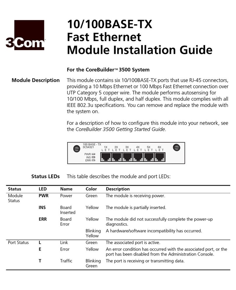
Table 1 and Table 2 list conventions that are used throughout this guide.
Table 1
Notice Icons
Icon Notice Type Alerts you to...
Information note Important features or instructions
Caution Risk of personal safety, system damage, or loss of data
Warning Risk of severe personal injury
Table 2
Text Conventions
Convention Description
Syntax
The word “syntax” means you must evaluate the syntax provided
and supply the appropriate values. Placeholders for values you must
supply appear in angle brackets. Example:
Enable RIPIP using:
SETDefault !<port> -RIPIP CONTrol = Listen
In this example, you must supply a port number for <port>.
Commands
The word “command” means you must enter the command exactly
as shown in text and press the Return or Enter key. Example:
To remove the IP address, enter:
SETDefault !0 -IP NETaddr = 0.0.0.0
This guide always gives the full form of a command in uppercase and
lowercase letters. However, you can abbreviate commands by entering
only the uppercase letters and the appropriate value. Commands are
not case-sensitive.
(continued)

2
A
BOUT
T
HIS
G
UIDE
Screen displays
This typeface represents information as it appears on the screen
.
The words “enter”
and “type” When you see the word “enter” in this guide, you must type
something, and then press the Return or Enter key. Do not press the
Return or Enter key when an instruction simply says “type.”
[Key] names Key names appear in text in one of two ways:
■
Referred to by their labels, such as “the Return key” or “the
Escape key”
■
Written with brackets, such as [Return] or [Esc].
If you must press two or more keys simultaneously, the key names are
linked with a plus sign (+). Example:
Press [Ctrl]+[Alt]+[Del].
Words in
bold-face
type Bold text denotes key features.
Table 2
Text Conventions (continued)
Convention Description

1
I
NSTALLATION
The NETBuilder II FDDILink Module is an extended-format module that occupies
two slots in the NETBuilder II 4-Slot or 8-Slot chassis and one slot in the 8-Slot
Extended chassis. The module comes in single-mode, multimode, and mixed-
(single- and multi-) mode versions.
This chapter describes how to install the FDDILink module into the NETBuilder II
bridge/router and includes the following procedures and information:
■
Software compatibility
■
Hardware requirements
■
Preparing for installation
■
Installing the module in a NETBuilder II 4- or 8-Slot chassis
■
Installing the module in a NETBuilder II 8-Slot Extended chassis
■
Cabling the module
For information about module features, refer to Chapter 2.
Software
Compatibility
All versions of the FDDILink module require version 9.3 or later of the
NETBuilder software. The module is not backward compatible and does not
support network boot or network dump procedures.
Hardware
Requirements
Use the information in this section to determine if your chassis will
accommodate the FDDILink module.
The newer 4-Slot chassis (assembly part number 20-0250-xxx or 20-0406-xxx),
8-Slot chassis (assembly part number 20-0249-xxx or 20-0407-xxx) or any
chassis labeled “EZBuilt” have one ejector tab for each module slot. The CEC
module slot, however, has two ejector tabs on all chassis. These new chassis
have a removable center column that allows for the installation of
extended-format modules, such as the FDDILink module.
The original 4-Slot and 8-Slot chassis do not have a removable center divider
between the slots and cannot accommodate extended-format modules.
Original 4-Slot and 8-Slot chassis have two ejector tabs for each module.
If your chassis does not have a removable center divider, but is still an older
model (product number 20-0250-xxx or 20-0244-xxx), you need a field
upgrade kit. To install FDDILink modules into the bottom slot of an original
4-Slot or 8-Slot chassis, you need to install EMI spring clips to ensure continued
compliance with emissions requirements. If your chassis does not already have
clips, contact your 3Com service organization to obtain spring clips
and

1-2
C
HAPTER
1: I
NSTALLATION
installation instructions (or field upgrade kit). Figure 1-1 will help you determine
if your chassis requires a filed upgrade kit to install an extended-format module
into the bottom slot. The illustration shows the 4-Slot chassis but is also applies
to the 8-Slot chassis. Chassis with two separate shielding strips in the bottom
slot require the upgrade kit to install the FDDILink module; chassis with one
shielding strip do not.
Figure 1-1
Determining the Need for a Field Upgrade Kit
Preparing for
Installation
To prepare to install an FDDILink module into the NETBuilder II system, follow
these steps:
CAUTION:
Take great care to keep the transceivers clean and dust free. Do not
remove the plastic protectors from the board or the end caps from the cable
until you are ready to connect. Immediately install protectors and end caps after
disconnecting.
1
Observe appropriate electrostatic discharge (ESD) precautions.
ESD can damage circuit board components. Failures resulting from ESD may not
be covered under your warranty. To prevent ESD:
■
Keep the module in its antistatic shielded bag until you are ready to install it.
■
Keep the optical transceivers in place until connecting a cable.
■
Do not touch pins, leads, or solder connections on the board.
■
Handle the board by the edges only.
■Store or ship the module in static-protective packaging.
Observe proper grounding techniques when handling the module: Use a foot
strap and grounded mat, or wear a grounded static discharge wrist strap.
2Inspect the module for shipping damage.
If you find any damage, contact the shipping company to file a report. If the
module must be returned to your network supplier, ship it in its original
shipping carton. If the original carton was damaged in shipment, repack the
system in a carton that provides equivalent protection.
1
2
4
3
OI
Chassis with two shielding strips in the bottom
slot needs the field upgrade kit. Chassis with one shielding strip in bottom slot
does not need the field upgrade kit.
Older chassis Newer chassis
1
2
4
3
OI
ABC ABC D
D
EF
EF
ETHERNET 6-PORT
10BASE-T
ABC ABC D
D
EF
EF
ETHERNET 6-PORT
10BASE-T

Installing the Module in a 4-Slot or 8-Slot Chassis 1-3
3Write down the serial number and the MAC address from the labels on the
module. You will need this information if you have to contact your network
supplier.
Figure 1-2 FDDILink Module
Serial number example: S/N: 4FZE123456
MAC address example: 080002 1A4B5C
The MAC address is also encoded in the module EEPROM.
Installing the Module
in a 4-Slot or 8-Slot
Chassis
When you install any extended-format module into the NETBuilder II 4-Slot or
8-Slot chassis, you must start with the first slot after the CEC module slot and
work down. If the first slot is occupied, move its contents to other slots and
install the FDDILink module into the now vacant slot.
To install the module into the NETBuilder II 4-Slot or 8-Slot chassis, follow these
steps:
■You will need small flat-blade screwdriver.
■You can safely install a module without turning off or rebooting the
NETBuilder II bridge/router. This is known as “hot-swap” capability.
1Remove the filler panel from the top slot.
If the cable strain relief bracket that came with your chassis is already installed,
remove it also.
Fi
g
ure 1-3 Remove filler
p
anel.
®
FDDI
B
A
MULTI/MULTI
STATUS A STATUS B STATUS
BYPASS
Serial number
MAC address
Loosen captive screws (with screwdriver if necessary)
and push ejector tabs to the side
Slide filler panels out of chassis
a
b
Ejector tab
Center column
cRemove center column
screw and center column
5
1
2
3
8
7
6
Captive screw
Filler panel
Center column screw

1-4 CHAPTER 1: INSTALLATION
CAUTION: Only remove the filler panels from the slots that will house the
FDDILink module. All unused slots require filler panels to maintain proper
cooling of the unit and regulatory compliance. Failure to cover open slots can
cause the NETBuilder II bridge/router to overheat, which will void the warranty.
2Slide the FDDILink module into the top slot.
Figure 1-4 Insert module into chassis
3Engage the ejector tabs and secure the module in the slot.
Do not use optical instruments to view laser output of the single- and
mixed-mode FDDILink modules.
WARNING: The use of optical instruments may cause eye hazard.
ATTENTION: L’utilisation d’instruments optiques peut être dangereuse pour
les yeux.
ACHTUNG: Die Verwendung von optischen Instrumenten kann eine Gefahr für
die Augen bergen.
ADVERTENCIA: El uso de instrumentos ópticos puede ser peligroso para
los ojos.
4Tighten the captive screws.
A solid connection of the front panel to the chassis is required for proper
operation. Do not use the screws to force the board into place.
Refer to “Cabling the Module” on page 1-6 to cable your FDDILink module.
Installing the Module
in a 8-Slot Extended
Chassis
To install the module into the NETBuilder II 8-Slot Extended chassis, follow these
steps:
■You will need a small flat-blade screwdriver.
■You can safely install a module without turning off or rebooting the
NETBuilder II bridge/router.
1Remove the filler panel from the slot you have selected.
If the cable strain relief bracket that came with you chassis is already installed,
remove it also.
4
5
1
2
3
8
7
6
2
7
®
FDDI
STATUS
MULTI MULTI
A STATUS B STATUS
B
A
BYPASS
MULTI/MULTI
a
bSlide module along guide
rails until it engages
ejector tab notch
With module right side up,
grasp left and right sides
of front panel

Installing the Module in a 8-Slot Extended Chassis 1-5
Figure 1-5 Removing a filler panel from an extended chassis
CAUTION: Remove only the filler panel from the slot that will house the
FDDILink module. All unused slots must be covered by filler panels to maintain
proper cooling of the unit and meet regulatory compliance. Failure to cover
open slots can cause the NETBuilder II bridge/router to overheat which will void
the warranty.
2Slide the FDDILink module into the slot.
Figure 1-6 Inserting an FDDILink module into an extended chassis
3Engage the ejector tabs and secure the module in the slot.
4Tighten the captive screws.
A solid connection of the front panel to the chassis is required for proper
operation. Do not use the screws to force the board into place.
CONSOLE AUXILIARY DIAGNOSTIC
4321
SELF TEST CPU ACT PKT FWD
STATUS
®
CEC
Push ejector tabs apart
b
Slide filler panel out of chassis
c
Loosen top and bottom
captive screws (with a
screwdriver if necessary).
Do
not loosen center
captive screw.
a
®
4
CONSOLE AUXILIARY DIAGNOSTIC
4321
SELF TEST CPU ACT PKT FWD
STATUS
®
CEC
MULTI/MULTI
®
FDDI
STATUS
MULTI MULTI
A STATUS B STATUS
B
A
BYPASS
Grasp left and right sides
of front panel and turn
module vertically so the
3Com logo is on the bottom
b
c
a
Slide module along guide
rails until it engages the
ejector tab notches
Finger tighten screws and
then gently tighten with a
small (1/8" - 3/16")
screwdriver

1-6 CHAPTER 1: INSTALLATION
Cabling the Module To cable and connect the FDDILink module, follow these steps:
1Remove the plastic protectors from the transceiver connectors on the module.
If you are only using one connector, leave the protector on the unused
connector.
CAUTION: Take great care to keep the transceivers clean and dust free. Do not
remove the plastic protectors from the board or the end caps from the cable
until you are ready to connect. Immediately install protectors and end caps after
disconnecting.
Figure 1-7 Removing plastic protectors
2Connect the appropriate network cable (not supplied) to the transceiver
connector.
■For the multimode transceiver, use multimode fiber of 62.5/125µmwith SC
connectors. An 11-db optical budget size allows cables up to 2 km long.
■For the single-mode transceiver, use single-mode fiber of 9/125µmwith an
SC connector. An 11-db optical budget size allows cables up to 15 km long.
Figure 1-8 Cabling the module
CAUTION: If keying pins were removed from the transceivers, it is possible to
insert the cable connector upside down. Take care to avoid this.
®
FDDI
A
MULTI SINGLE
B
MULTI/SINGLE
Press the cable connector
into the transceiver connector
until the external fasteners click
®
FDDI
A
MULTI SINGLE
B
MULTI/SINGLE
B
A

2OVERVIEW OF THE FDDILINK
MODULE
This chapter describes the features, specifications, and typical use of the FDDILink
module for the NETBuilder II bridge/router.
Module Features Table 2-1 summarizes the features of the FDDILink module.
Table 2-1 FDDILink Module Features
Feature Summary
Hot-swap capability Allows you to install, or remove and reinstall, the module without
turning of the NETBuilder II bridge/router.
Compatibility
Multimode
Single-mode
Connects to any FDDILink network through SC connectors. Transceiver
accepts 100 µm 62.5 center core, multimode fiber with 62.5 µm core
and 125 µm cladding.
Connects to any FDDILink network through SC connectors. Transceiver
accepts 100 µm 8.7 center core, single-mode fiber with 8.7 µm core
and 125 µm cladding.
Connections Single- or dual-attached capabilities.
Keying Supports and accepts A, B, or S type ports for network connection.
Cable support
Multimode
Single-mode
Accepts multimode duplex fiber of 62.5/125 µm. An 11-db optical
budget size allows cables up to 2 km long.
Accepts single-mode duplex fiber of 8.7/125 µm. An 11-db optical
budget size allows cables up to 15km long.
Flexible topology Topology and capacity can be configured by setting conditions on the
network external to the NETBuilder II base system. The capacity and
topology of the FDDILink network is not fixed. Capacity is determined
by a combination of cable lengths and connector capabilities.
Accessible informa-
tion on the EEPROM Provides FDDILink module product information that can be accessed via
the monitor utility or user interface.
Interface speed 25 MHz.
Controller speed 12.5 MHz.
Clocks 25 MHz symbol clock rate.
12.5 MHz byte clock rate.
Laser safety Single- and mixed-mode FDDILink modules are certified Class 1 laser
safe.

2-2 CHAPTER 2: OVERVIEW OF THE FDDILINK MODULE
Typical Network
Configuration Figure 2-1 shows a typical use of a mixed-mode FDDILink module and the
NETBuilder II bridge/router in a network.
Figure 2-1 Typical Mixed-mode FDDILink Module and NETBuilder II Bridge/Router
Network
Module Components This section describes the components of the FDDILink module (see Figure 2-2).
Figure 2-2 FDDILink Module Components
LEDs The FDDILink module has three LEDs: One indicates the status of the whole
FDDILink module and the other two indicate the status of the physical fiber
connection to each transceiver. The A STATUS LED corresponds to the left
transceiver, and the B STATUS LED corresponds to the right transceiver. Table 2-2
explains the LED states.
CUPERTINO
SUNNYVALE
SANTA CLARA
campus
M
u
l
t
i
m
o
d
e
f
i
b
e
r
S
i
n
g
l
e
-
m
o
d
e
f
i
b
e
r
s
i
n
g
l
e
-
m
o
d
e
f
i
b
e
r
®
STATUS
MULTI MULTI
A STATUS B STATUS
B
ABYPASS
®
STATUS
MULTI MULTI
A STATUS B STATUS
B
ABYPASS
FDDILink
FDDILink
NETBuilder II
bridge/router
in building 100
NETBuilder II
bridge/router
in building 200
Single-mode
A transceiver Multimode
B transceiver Multimode
A transceiver Single-mode
B transceiver
FDDI SC
connectors
Optical
bypass
connector
Status LEDs
J1 J2 J3
®
FDDI
B
A
MULTI/MULTI
STATUS A STATUS B STATUS
BYPASS

Specifications 2-3
FDDILink Module
Connectors Table 2-3 describes the FDDILink module connectors.
Specifications Table 2-4 lists the physical dimensions of the module, and Table 2-5 lists the
current consumption.
Table 2-2 LED States
LED Color Indicates
STATUS Off No power to module
Green Normal Operation
Yellow Paths not enabled (may be caused by duplicate address on FDDI ring)
Red Fault or reset
A STATUS Green Normal Operation
Yellow Self-test or stand-by mode (stand-by mode occurs if Transceiver B is
connected to a concentrator master port)
Red Fault or reset
B STATUS Green Normal Operation
Yellow Self-test
Red Fault or reset
Table 2-3 FDDILink Module Connectors
Location Connector(s) No. of Pins Purpose
Backplane connector J1 and J3
J2 48-pin
8-pin Connects module to the core bus.
Power connector.
Front panel Optical bypass
connector 6-pin Allows the network to continue
in primary and secondary mode
even if the NETBuilder II
bridge/router is turned off. Dis-
abled in the single- and
mixed-mode FDDILink modules.
Front panel Two FDDI SC
connectors 2-pin Connects module to fiber with an
SC connector.
Table 2-4 Physical Dimensions
Attribute Description
Length 9.3 in (22.3 cm)
Width 10.8 in (27.4 cm)
Height 0.6 in (1.5cm)
Weight 1.2 lbs (0.54 kg)
Table 2-5 Maximum Current Consumption
+5 Volts +12 Volts -12 Volts
3.8 amp 0.1 amp 0.2 amp

2-4 CHAPTER 2: OVERVIEW OF THE FDDILINK MODULE

3TROUBLESHOOTING AND REPLACING
THE MODULE
This chapter describes how to troubleshoot and replace the FDDILink module.
Troubleshooting Table 3-1 describes common malfunctions that can occur with the module,
possible causes, and actions to take. If you are unable to resolve a problem,
contact your network supplier. Refer to Appendix A for information about who
to contact in your area.
Replacing the Module If any component in the module fails, you must replace the module.
To remove and replace the module, follow these steps:
■You will need a flat-blade screwdriver.
■You can safely install a module without turning off or rebooting the
NETBuilder II bridge/router.
1Disconnect any network cabling from the FDDILink module.
Do not use optical instruments to view laser output of the single- and
mixed-mode FDDILink modules.
Table 3-1 Troubleshooting the FDDILink Module
Symptom Cause and Action
The following message is displayed at start-up:
FDDI Interface: Self Tests failed -
slot X
(The value of X can be 1 through 4 or 1 through 8,
depending on whether you have a 4- or an 8-Slot
NETBuilder II chassis.)
Self-test failure
■Check to see if the module is inserted completely into the NETBuilder II
chassis.
■Make sure there are no bent pins on the NETBuilder II backplane.
If you still have a self-test failure, contact your network supplier.
The STATUS LED is off when there is power to the
system and other installed modules are operating. Disabled module
The module may not be properly connected to the NETBuilder II
backplane. Remove and reinsert the module.
If it is still not working, contact your network supplier.
The STATUS LED is red. Error condition
■Check that all cable connections are intact.
■Check that the NETBuilder II bridge/router is operating correctly.
■Check that the network you are connected to is operating correctly.
■Check that the connected serial device is operating correctly.
■With a single-fiber module, connect port A to port B. If the LED goes
green, the module is probably not faulty.
If none of these actions solve the problem, replace the module and/or
contact your network supplier for assistance.

3-2 CHAPTER 3: TROUBLESHOOTING AND REPLACING THE MODULE
WARNING: The use of optical instruments may cause eye hazard.
ATTENTION: L’utilisation d’instruments optiques peut être dangereuse pour
les yeux.
ACHTUNG: Die Verwendung von optischen Instrumenten kann eine Gefahr für
die Augen bergen.
ADVERTENCIA: El uso de instrumentos ópticos puede ser peligroso para
los ojos.
2Use the screwdriver to unscrew the two captive screws that anchor the module
in the slot until they disengage from the chassis. Do not remove the screws
from the front panel.
3Push the tab outward from the FDDILink module.
The module disengages from the NETBuilder II backplane and partially ejects
from the slot.
4Use both hands to grasp the module and gently pull it from the slot.
Install the new module using the procedure in Chapter 1.

ATECHNICAL SUPPORT
3Com provides easy access to technical support information through a variety of
services. This appendix describes these services.
Information contained in this appendix is correct at time of publication. For the
very latest, we recommend that you access 3Com Corporation’s World Wide
Web site as described below.
Online Technical
Services 3Com offers worldwide product support 24 hours a day, 7 days a week,
through the following online systems:
■World Wide Web site
■3Com Bulletin Board Service (3ComBBS)
■3ComFactsSM automated fax service
■3ComForum on CompuServe®online service
World Wide Web Site Access the latest networking information on 3Com Corporation’s World Wide
Web site by entering our URL into your Internet browser:
http://www.3Com.com/
This service features the latest information about 3Com solutions and
technologies, customer service and support, news about the company, NetAge®
Magazine, and more.
3Com Bulletin Board
Service 3ComBBS contains patches, software, and drivers for all 3Com products, as well
as technical articles. This service is available through analog modem or digital
modem (ISDN) 24 hours a day, 7 days a week.
Access by Analog Modem
To reach the service by modem, set your modem to 8 data bits, no parity, and
1 stop bit. Call the telephone number nearest you:
Country Data Rate Telephone Number
Australia up to 14400 bps 61 2 9955 2073
Brazil up to 14400 bps 55 11 547 9666
France up to 14400 bps 33 1 6986 6954
Germany up to 28800 bps 4989 62732 188
Hong Kong up to 14400 bps 852 2537 5608
Italy (fee required) up to 14400 bps 39 2 27300680
Japan up to 14400 bps 81 3 3345 7266
(continued)
Table of contents
Other 3Com Control Unit manuals

3Com
3Com NETBuilder II User manual

3Com
3Com WL-463 User manual

3Com
3Com LINKBUILDER 3C18500 User manual

3Com
3Com SuperStack II 3C81665 User manual

3Com
3Com 3CB9RG4 User manual

3Com
3Com 2103R-CSDI User manual

3Com
3Com BETA User manual

3Com
3Com CoreBuilder 9000 ATM Interface Module User manual

3Com
3Com CoreBuilder 5000 User manual

3Com
3Com NETBuilder II DPE 80 User manual