manuals.online logo
Brands
  1. Home
  2. •
  3. Brands
  4. •
  5. WAREMA
  6. •
  7. Control Unit
  8. •
  9. WAREMA MSE Compact 1 UP User manual

WAREMA MSE Compact 1 UP User manual

warema_890022_alhb_en_v3•2020-10-01 We reserve the right to carry out improvements 1
Operating and Installation Instructions
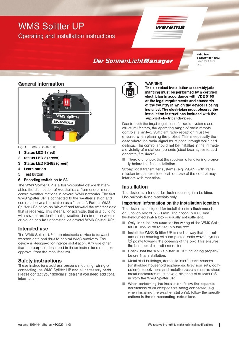
MSE Compact 1 UP
Keep for future use!
Valid from October 1st, 2020
General
Fig. 1 MSE Compact 1 UP
The motor control unit MSE Compact 1 UP is an electronic
control unit for the direct control of 230 V AC sun protec-
tion drives. The drives and the MSE Compact 1 UP are
supplied via the 230 VAC main line. In spite of its compact
design, the device is equipped with a built-in power supply
which provides the internal supply voltage. Furthermore,
the MSE Compact 1 UP comes with a switch to select
time logic (factory-set) or permanent logic to permit type-
specific operation of various sun protection systems. It is
intended for installation in a deep flush-mounted switch
box.
The sun protection system can be operated through local
pushbuttons as well as through a central sun protection
control unit (e.g. Wisotronic). Several MSE Compact 1
UP can be combined in a group and operated jointly by
means of a single pushbutton.
Intended use
The device was developed to control sun shading systems.
The approval of the manufacturer must be obtained for
uses outside of the purposes listed in these instructions.
Safety instructions
ARNINGW
Electrical installation must be performed
by a certified electrician in accordance
with VDE0100 or the legal requirements
and standards of the country in which the
device is being installed. The electrician
must observe the installation instruc-
tions included with the supplied electrical
devices.
WARNING
If hazard-free operation cannot be as-
sumed, the device may not be started or
must be deactivated. This assumption is
justified
 if the housing or the supply lines show
signs of damage,
 the device is no longer working
WARNING
It is important to comply with the follow-
ing points of instruction in the interest of
personal safety!
■Do not allow children to play with the operating ele-
ments of the control or remote control! Store the re-
mote controls out of range from children!
■Make sure that no persons or objects are in the range
of movement of the driven parts (blinds, window, etc.!
■Disconnect the device from the supply voltage if clean-
ing or other maintenance work must be performed!
Information on the electrical installation
An on-site overload current disconnecting and isolating
switch to switch off the entire system must be provided.
When using control lines according to VDE 0815 or not
approved for 230 V AC, e.g. JY(St)Y leads, the enclosed
silicon tubes must be pulled over the wires of of the 24 V-
control line and the pushbutton line.
The device meets the EMC guidelines for use in residential
and commercial areas.
Mounting
The MSE Compact 1 UP is intended for flush-mounted
installation in a commercially available deep flush-mounted
switch box ∅ 60 mm; the installation in a deep flush-
mounted splitting box ∅ 70 mm is recommended. Only
lines for the wiring of the MSE Compact 1 UP should be
routed through this box.
OTICEN Only one MSE Compact 1 UP may be installed
per flush-mounted box.
OTICEN Set the encoding switch S1 according to the
desired function (Fig. 4)
The installation must be done indoors! The device is not
suitable for use in rooms requiring moisture-proof installa-
tions! The electrical connection of the MSE Compact 1 UP
is made with spring-loaded terminals (Fig. 3) according to
the following wiring diagram (Fig. 4).
Commissioning
The device is ready for operation after the installation has
been completed and the supply voltage applied.
warema_890022_alhb_en_v3•2020-10-01We reserve the right to carry out improvements
2
Functionality
Switching between time logic or permanent logic
(switch S1)
The switch S1 (see Fig. 4) is used to select the time
logic (factory-set) or permanent logic.
Local operation with time logic (ZL):
After actuating the local pushbutton, the sun protection
product moves to the corresponding direction. If the push-
button remains pressed for more than 2 seconds, the MSE
Compact 1 UP switches to the locked state. Thereafter,
the pushbutton can be released. The sun protection
product moves until the run time of approx. 3 minutes has
lapsed. To cancel the locked state and stop the motor, the
button opposite to the move command must be pushed
briefly. To only turn the slats, simply push the local button
for a brief time.
Local operation with permanent logic (PL):
This control behaviour is especially suited, e.g. for roller
shutters: After pressing the local pushbutton, the roller
shutter moves into the corresponding direction and imme-
diately switches to the locked state. The pushbutton can
be released immediately and the roller shutter moves until
the set run time of 3 minutes has lapsed. To cancel the
locked state and stop the motor, the button opposite to the
move command must be pushed briefly.
Central operation:
The local operation is locked for the duration of the central
operation, a possibly existing locking mode is thereby
deleted.
OTICEN If the drive does not reach the limit switch "Up"
or "Down" within 3 minutes, then the drive is
automatically switched off, regardless whether
a local or central command was given.
Group formation via the control line:
Several MSE Compact 1 UP can be switched as a group
through the control line and centrally operated via a push-
button.
Refer to the corresponding wiring diagram on page 4!
Maintenance
There are no parts within the device that require mainte-
nance.
Cleaning
Clean the enclosure with a soft, damp cloth. Do not use
any scouring agents, solvents or steam cleaners!
Liability
Failure to comply with the product information in these
instructions and use of the device in a manner that con-
travenes its intended use and purpose may result in the
manufacture refusing to honour warranty claims for prod-
uct damage. In this case, liability for consequential harm
to persons or damage to property will also be excluded.
Follow also the instructions in the operating manual of
your sun shading system. The automatic or manual opera-
tion of the sun shading system when iced over as well as
using the sun shading system during severe weather may
cause damages and must be prevented by the user by
taking suitable precautions.
Disposal
After its use, the device must be disposed off according to
legal regulations or returned to your local recycling centre!
Technical data
MSE Compact 1 UP min. typ. max. Unit
230 V AC supply
Operating voltage 198 230 253 V AC
Current consumption 8 10 12 mA
Effective power
consumption 2 W
Drive output
Switching capacity at
230 VAC / cos ϕ=0.6 700 VA
Minimum load at 5 VDC 10 mA
Control input
Central voltage active 6 24 30 V DC
Central current active 1 1,5 2 mA
Central voltage inactive –0,5 0 2,5 V DC
Local voltage active 6 24 30 V DC
Local current active 1 1,5 2 mA
Local voltage inactive –0,5 0 2,5 V DC
Housing
Dimensions See Fig.2
Weight 50 g
Degree of protection-
Through installation in the
flush-mounted-box
IP 20
Protection class
(without PE) II
Miscellaneous
Conformity available at www.warema.de/ce
This device meets the EMC directives for use in residential and
commercial areas.
Ambient conditions
operating temperature 0 20 40 °C
storing temperature 0 20 50 °C
Humidity
(not condensing) 10 40 85 %Frel
Pollution degree 2
Terminals
Main line 0.5...1.5 mm2
Motor lead 0.5...1.5 mm2
Pushbotton and control line 0.12...0.5 mm2
Article number
MSE Compact 1 UP 1002 683
WAREMA Renkhoff SE
Hans-Wilhelm-Renkhoff-Strasse 2
97828 Marktheidenfeld
Germany
3
warema_890022_alhb_en_v3•2020-10-01 We reserve the right to carry out improvements
After the wire has been stripped, it is pressed into the ter-
minal (1) until the insulation of the wire enters the terminal
and the lead is held securely in the terminal (2). To detach
the connection, the corresponding unlocking button must
be pushed all the way in with a screwdriver; the lead can
then be pulled out of the terminal (3).Fig. 4: Wiring diagram
24.0 mm 48.5 mm
48.5 mm
Fig. 2 Housing dimensions
23
Fig. 3 Connecting and detaching the line connections
warema_890022_alhb_en_v3•2020-10-01We reserve the right to carry out improvements
4
UP
DOWN
+
PE
L1
N
PE
L2
N
Power line
230 V AC 50 Hz / 6 A
Power line
230 V AC
to next MSE
Motor 1
1
1
2
2
3
3
123
M 1~
Terminal
Plug connection
Motor 2
1
1
2
2
3
3
123
M 1~
Plug connection
Motor 3
1
1
2
2
3
3
123
M 1~
Plug connection
Attention!
Only one drive may be
connected per MSE!
LLNN
X1
N
Motor
230V~
X2
S1
ZL | PL
X3
Netz
230V~
MSE
Kompakt 1
UP
LLNN
X1
N
Motor
230V~
X2
X3
Netz
230V~
LLNN
X1
N
Motor
230V~
X2
X3
Netz
230V~
Group pushbutton
(Motor 1 + 2)
Single pushbutton
(Motor 3)
F
L2 PEN
Power line (2.Phase)
230 V AC 50 Hz / 6 A
MSE
Kompakt 1
UP
MSE
Kompakt 1
UP
S1
ZL | PL
S1
ZL | PL
+
0V
P
Lokal Zentral
+
0V
P
Lokal Zentral
+
0V
P
Lokal Zentral




 
bl
gnyl
bn
bk
bl
gnyl
bn
bk
bl
gnyl
bn
bk
+
0 V
Central down
Central up
Group down
Group up
to next MSE



F

P
Connection:
Floating contacts of the
sun shading control system/
GA Compact
+
DOWN
UP
E
P/C
For further information, see
documentation to wiring
diagrams "Anschlusspläne",
Art. No.: 816 345
- Max. group size of 200 motor control units, see voltage drop diagram.
- Central control line length, see voltage drop diagram.
- The power line length is limited by the total motor current. The
maximum number of drives per circuit depends on their current
consumption and the upstream fuse.
- Only pushbuttons may be used.
- When using control lines according to VDE 0815 or not approved for
230 V AC, e.g. JY(St)Y leads, the enclosed silicon tubes must be
pulled over the wires of the 24 V- control line and the pushbutton line.
Legend:
 4 x 2 x 0,8 mm ∅ screened, single wired
 2 x 2 x 0,8 mm ∅ screened, single wired
 H05RR-F4G 0,75 mm2 bk, Type WAREMA
3 x 1,5 mm2
UP
DOWN
P
Fig. 4 Wiring diagram MSE Compact 1 UP

Other WAREMA Control Unit manuals

WAREMA GA Kompakt User manual

WAREMA

WAREMA GA Kompakt User manual

WAREMA climatronic WebControl User manual

WAREMA

WAREMA climatronic WebControl User manual

WAREMA Minitronic Dialog User manual

WAREMA

WAREMA Minitronic Dialog User manual

WAREMA WMS WebControl User manual

WAREMA

WAREMA WMS WebControl User manual

WAREMA GA Kompakt User manual

WAREMA

WAREMA GA Kompakt User manual

WAREMA MSE Haustechnik ZL User manual

WAREMA

WAREMA MSE Haustechnik ZL User manual

WAREMA WMS Splitter UP User manual

WAREMA

WAREMA WMS Splitter UP User manual

WAREMA MSE Compact 2 REG User manual

WAREMA

WAREMA MSE Compact 2 REG User manual

WAREMA Omnexo User manual

WAREMA

WAREMA Omnexo User manual

WAREMA GA Kompakt User manual

WAREMA

WAREMA GA Kompakt User manual

WAREMA Uniswitch ZL User manual

WAREMA

WAREMA Uniswitch ZL User manual

WAREMA WMS WebControl pro User manual

WAREMA

WAREMA WMS WebControl pro User manual

Popular Control Unit manuals by other brands

WAGO 750-489 manual

WAGO

WAGO 750-489 manual

Sanela SLS 02PT Instructions for use

Sanela

Sanela SLS 02PT Instructions for use

National Instruments ATCA-3671 Getting started guide

National Instruments

National Instruments ATCA-3671 Getting started guide

Aerotech UFM-ST Hardware manual

Aerotech

Aerotech UFM-ST Hardware manual

Knick Protos LDO 3400-170 user manual

Knick

Knick Protos LDO 3400-170 user manual

CyberPower 14/351mm user manual

CyberPower

CyberPower 14/351mm user manual

Satel GSM-X Quick installation guide

Satel

Satel GSM-X Quick installation guide

Burkert 2103 Series operating instructions

Burkert

Burkert 2103 Series operating instructions

Ross Vision 4800DR-324-02 installation guide

Ross

Ross Vision 4800DR-324-02 installation guide

Satel ETHM-A Quick installation guide

Satel

Satel ETHM-A Quick installation guide

Honeywell BSM Installation and setup guide

Honeywell

Honeywell BSM Installation and setup guide

Tektronix KEITHLEY 7710 Instructions for use

Tektronix

Tektronix KEITHLEY 7710 Instructions for use

Ebyte E220-900T30D user manual

Ebyte

Ebyte E220-900T30D user manual

Roland XV-5050 Turbostart

Roland

Roland XV-5050 Turbostart

MDT Technologies SCN-LOG1.01 operating instructions

MDT Technologies

MDT Technologies SCN-LOG1.01 operating instructions

ADLINK Technology USB-1901 user manual

ADLINK Technology

ADLINK Technology USB-1901 user manual

Festo DRRD-PS1 Series operating instructions

Festo

Festo DRRD-PS1 Series operating instructions

Beninca DA.BA operating instructions

Beninca

Beninca DA.BA operating instructions

manuals.online logo
manuals.online logoBrands
  • About & Mission
  • Contact us
  • Privacy Policy
  • Terms and Conditions

Copyright 2025 Manuals.Online. All Rights Reserved.