3D Creations North American P 51 D Mustang User manual

1
North American P 51 D Mustang
By 3D Creations
Paper Scale Model Kit
The Items needed for assembly:
1. Glue stick
2. Liquid glue
3. Instant Bond type glue
4. Sharp Scissors
5. A ruler with a good straight edge
6. Round tooth picks
7. Cardboard from the back of a pad of paper or from a cereal box
8. Tweezers
9. An Exato knife or razor blade
Tips:
1. When cutting out the pieces to be assembled always cut slightly on the color side of
the line. Leaving a white edge will detract from the appearance of the model. Use
caution when cutting. Only remove enough color to eliminate the white edge. Cutting
the pieces undersize will alter the fit when gluing them together.
2. Any white area bordered by a black line is not to be cut off. This area is intended for
attachment beneath the adjoining piece.
3. Because of the need for rounded surfaces many of the pieces have to be assembled in
a cup like fashion. This is accomplished in the same manor you use to cup your
hands. By drawing together and overlapping the two pieces starting at their narrowest
overlap moving to the widest, the piece will take on a cup like appearance.
4. Use the solid glue stick unless otherwise specified. This helps eliminate applying too
much glue.
5. When applying glue, whenever possible, place it on the piece that will be on top of
the next. This also helps avoid applying too much glue.
6. Scoring creased folds using a straight edge helps make very straight creases. A letter
open is what I prefer.

2
Fuselage Assembly
Cut out parts #1, #2, #3,and #4. Glue the wing mount
sections (parts #3 & #4) to the fuselage parts #1 & #2
matching up the paint scheme to insure that they are
mounted on the correct side. Next cut out parts #6, #7, and
#24. Glue part #7 to part #2 as shown in figure 1. Now glue
part #1 to the other side of part #7 in the same way.
See figure 2.
Now for your first part assembly
that requires a forming of the pieces
to be joined. First place part #6 in it’s
correct place (Directly behind #7
overlapping it slightly). Pay careful
attention to its placement using the
printed panel lines and color to help
you line it up. As the piece is
attached you
must draw the
sides of the
fuselage into piece #6 making sure #6 and #7 stay lined up. If done
correctly the top of the nose section should have a slight cup shape to
it. At this point you must curl the nose section to its desired shape
before you can attach any other pieces. What needs to be done is to
roll part #7 an #6 without
creasing it while leaving the
fuselage sides flat. This allows
you to mount the following pieces without wrinkling
them. See figure 3. It will naturally snap back some
from this position which is OK. You’re just
establishing the shape right now.
Now it is time to bend the light blue tabs at the rear
of the fuselage. See figure 4. This will become the
rudder mounting area later in the construction. These
blue tabs are to be bent inward at a right angle to the fuselage. First make a small cut
along the front edge of the tab down to the white line. This helps
make a clean fold.
Score and crease
along the white line
at the bottom of the
tab and fold. Now
draw the two blue
tabs together and
glue one tab exactly
on top of the other.
You will need to

3
slightly warp the fuselage to get the desired fit of the tabs and that is exactly what we
want. Now cut out part #24. Look carefully and you will find a short gray line that runs
lengthwise on the center of the piece. This is where the antenna mast will be mounted
later. While the piece is still flat you need to cut a slot where the line lies now. See figure
5. Now you are ready to mount part #24 to the fuselage. Remember to check the fit
before applying glue to insure proper placement. When the top part of the fuselage is
complete it should not be flat. It should be raised in the center along the full length of the
fuselage see figure 6. If you can draw the sides down like shown in figure 3 the top
should be evenly curved along the length of the entire piece with no wrinkles. Cut out
part #23 the antenna mast. Fold this piece in half and glue the mast portions together. The
mounting tabs are to be folded out at a 90-degree angle. Apply glue to the top of the tabs
and thread the mast through the slot in part #24 from the inside out.
OK, now that we are done with the top of the fuselage lets start on the bottom. First let
me give you a word of warning. This is one of the more difficult
assemblies of the kit so be sure to fit everything up before you glue.
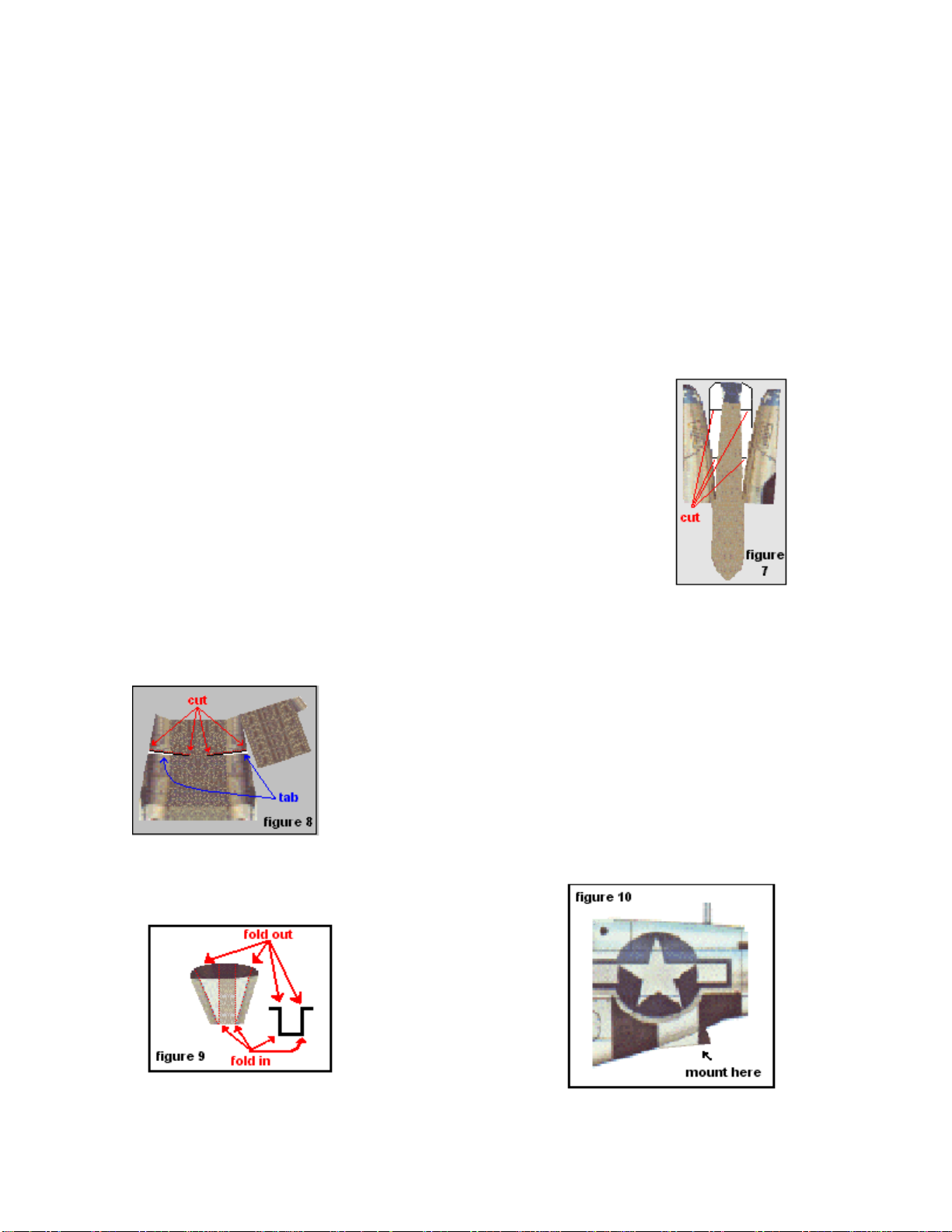
Find part #22 and cut it out remembering to leave the white areas
that are bordered by a black line attached. Make cuts along the four
black lines that run in from the edges of the white tabs. The white
tabs are intended to remain attached to the piece that resembles a
necktie and cut away from the two sidepieces. Don’t cut the two
sidepieces completely off. There should be a very small area left that
connects them to the center section. See figure 7. Apply glue to the
white tabs and glue them to the backside of the sidepieces. Attach
each section of tab one at a time starting from the bottom working up
to the top. Take care to cover the white area only. The warping of the parts becomes
increased with each tab. This creates the shape needed to form the bottom of the nose
section. This piece needs to be aligned accurately. Use the color scheme of the aircraft to
mount part #22 to the nose section of the fuselage.
Locate part #25 and cut it out. Like part #22 the white tabs are
to remain attached to the center section of the piece. Two cuts
are to be made on the scoop area. Make those cuts on the color
side of the black line. The white area is not to be removed.
Although they are extremely small they are gluing tabs.
Draw the pieces together just enough to cover the small white
tabs and glue into place. Glue the sides to the center section in the same manor as part
#22. Next shape the piece so that the bottom is flat with the sides bent upward (NO
CREASE) at a 90-degree angle to the bottom. Now
fold the top of the air scoop over and glue the tab to
the opposite side. Glue the
completed part to the
fuselage just aft of the
wing mount once again
using the color scheme to
determine the proper
alignment. I have found
that by lining up on the stars first everything else will
fall into place. A pen is useful when applying this part. Insert it in the fuselage and use it
for something to push against when pressing the piece in place.

4
Locate part #5 and cut it out. Shape the piece in to a U before mounting. (Do not crease).
The white tabs at the tail are to be creased upward at a 90-degree angle for the tail mount
that comes later.
Cut out part #26. And fold with a crease along the paint scheme lines. Make the fold as
shown in figure 9. Mount as shown in figure 10. This completes the fuselage and it can
be set aside for now.
Landing Gear Assembly
At this point you have the option to build the kit
with landing gear or without. If you chose to build
with out gear skip this section.
Locate parts #41 and #42. Cut these parts out
using the black boarders that surround them. These
parts are to be used as templates for the
construction of the gear struts. Carefully notch
both of the points indicated in figure 10. I use
fingernail clippers to notch the toothpicks. Be
careful not to cut them in half. The notches at
these two points allow you to bend the toothpicks
at those points without separating them.
This adds strength and makes construction much easier. Super Glue the joints of
toothpicks directly to each other and the template. After the glue is set cut away the
excess template. Trim away as much as possible with out weakening the structure. Cut
piece #41 to shape then Super glue it on the opposite side of the strut. The toothpicks
should now be sandwiched between the two templates. Repeat this process for the second
strut. Cut out part #28 and #29. Attach part #28 as shown in figure 11. Use Super Glue
for all applications regarding the landing gear unless otherwise specified. Wrap part #28
around the strut and attach see figure 12. Roll the strut 180-degrees and that will expose
what is yet to be covered on the bottom of the piece. See figure 13. Now place part #28
on the strut as shown in figure 14. Wrap and glue into place. Glue part #39 with glue
stick as shown in figure 15 and wrap tightly and evenly to give you a finished look as
seen in figure 16.

5
Parts #9 are to be glued down flat to cardboard and then cut to shape. Part #9 is not
necessary if you are not going to build the kit with landing gear. Sandwich the landing
gear strut between two of the wing spars (part #9) as shown in figure 17. Make sure that
the two spar edges are matched up evenly and the struts hang at a 90-degree angle from
them. Bad alignment of these parts will cause the landing gear to hang crookedly beneath
the wings.

6
Wing Assembly
For the wing assembly you will need to cut out parts # 8 and 10. Before folding the wing
to shape cut out the black dots that lie in the white areas of the wing. An exacto knife
works well for this. To get the correct alignment when folding the wing double them over
aligning the two areas specified in figure 18. While holding the alignment carefully
crease the trailing edge.
Fold the leading edge tab over along the line shown in figure 19. Do not glue it yet.
Open the wing up and thread the landing gear strut through the hole that was cut earlier.
Make sure the correct strut is on the correct wing. After checking to make sure the gear
hangs straight and checking what will be the wheel alignment glue the bottom portion of
the spar to the wing. Next apply glue to the top of the spar and the leading edge tab.
Close up the wing folding the leading edge tab around and attaching it to the underneath
side of the leading edge. Apply glue to the very edge of the wing tip and pinch the edges
together. Figure 20 shows the completed wings with the gear properly installed.

7
Carefully inspect the edges of the wings and trim any of the edges that don’t match up
perfectly. Now cut out parts #11 and #12. On these parts you will notice white glue tabs
that are to be left connected to the
green central spar. You will also notice
that the wing sections are to remain
attached at the top and bottom of the
spars. See figure 21.
Figure 22 shows the removal of the section that allows for the landing gear strut. This
piece need not be removed if landing gear is not used.
Now score and fold back at a 90-degree angle the white glue tabs bordering the central
spar. Score and fold the wing sections back at 90-degree angle. Apply glue to the glue
tabs and attach the wing to them. See figure 23. Do not fold and glue the leading edge
and trailing edge glue tabs.
As you can see this part is to be slid over the
unfinished portion of the wing. Using liquid glue
and a model paintbrush apply glue (sparingly) to
the bottom section. Attach the bottom section to
the wing first. Now brush glue on the top section
and attach it second. You will find that a small
amount of warping is necessary to correctly line
up the paint scheme. This is to create the
necessary dihedral of the wings. At this point trim any excess away from the edges. Fold
the two edge tabs over and glue into place. Repeat this operation with the other wing.
Place the two completed wing sections flat on a table (gear up). Apply glue to the central

8
spars and butt them together. Cut out parts #16 and 17. Glue part #17 over the seam
between the two wings. Trim the edges if necessary. Flip the wing over and check the
dihedral. It should be right at one inch. See figure 24. Glue part #16 over the seam on the
top of the wings making sure you hold that 1 inch dihedral while doing it. Trim off any
excess that might hang off at the edges.
Mounting the Wing
First prepare the fuselage for the wing by folding in all the glue tabs on the wing mount
section of the fuselage. Do not apply glue at this time. It is also necessary to carefully
fold back (with no crease) the end of part # 22 to allow the landing gear strut to pass by.
This step is not necessary if the gear is not present. Carefully slide the wing through the
wing mount area on the fuselage. This is
intentionally a tight fit. Use patience and be
gentile completing this task. After checking the
alignments to insure that wing is centered and
squares with the fuselage apply glue to the tabs
inside the fuselage. This is accomplished by
using liquid glue and a modeling paintbrush
extended into the nose and tail holes in the
fuselage. Apply glue to the underneath side of
part #22 and lay it back down into place. Cut out
parts #13. Double check the alignment and glue
these parts to the fuselage and wing as shown in
figure 25.

9
Elevator and Rudder Construction
Cut out elevator parts #14 and 15. Score and fold along the lines indicated in figure 26.
Apply glue to the trailing edge tab and the
very edge of the elevator wing tip. Fold the
elevator halves together then fold the trailing
edge tab back in to place. Now hold the
elevator by its edges and squeeze them
together so that the sides bow out giving the
elevator an elliptical shape. Fold the bottom
tab down at a 90-degree angle. Do not bend
the light blue tap. Trim off any edges that
need it. Repeat this procedure for the other
elevator section.
Apply glue to the two tabs and mount to the
tail section of the fuselage as shown in figure
27. Use the paint scheme to locate the proper
placement of the lower glue tab. Now cut out part #20 the rudder. Take note
of the small cuts that are to be made in the
glue tabs at the base of the rudder mount.
Score and fold the rudder in half at the
trailing edge. Now score, fold and glue all
the glue tabs on the leading edge. Score all
the lower glue tabs and fold them out at a
90-degree angle. At this point squeeze the
rudders edges to give it an elliptical shape.
Apply glue to the top edge and press it
together. Curl the two front tabs slightly to
match the curve
of the fuselage
prior to gluing to
make instillation
easier. See figure 28. Using liquid glue brushed on in a thin
layer mount the
rudder in place. After
insuring its
alignment use a
toothpick to press the
tabs into place. Now
cut out parts #18 and
19. These pieces are
to be bent at a 90-
degree angle outward and glued to the rudder
and elevator simultaneously. This covers the
exposed seam. See figure 29.

10
Final Landing Gear Assembly
Cut out parts #32. Apply glue
to the backside of these parts
and apply them to the landing
gear struts as shown in figure
30.Cut out parts #36,37 and 38
as a group using the black
boarder that surrounds them.
Glue this group onto a piece of
cardboard and then cut them
out individually.
Laminate the six pieces together to form
the wheels. Each wheel should be 3/16”
thick. Extra templates are provided to
achieve this width if necessary. Mount
the wheels as shown in figure 31. Some
trimming of the gear strut may be
necessary to obtain a square mounting.
Cut out the right landing gear door (part
#30) and fold as shown in figure 31.
Apply glue to the inside portions of the
gear door and press them together. Leave
the sections that are folded out free of
glue. Now cut out part #31 and glue these
parts into place as shown in figure 32.
Repeat this process for the left side.

11
.
The next step is optional. The
wheel doors can be put on or left
off. When the doors are open they
are in the service position. When
the aircraft is taxing or takes off
these doors are closed. This was not
an option on the earlier models of
the Mustang. If you choose to not
display the doors in the service
position skip this step. Cut out
parts#45 and 46. Fold and glue the
doors as shone in figure 33. Mount
them as shown in figure 34.

12
Cut out parts #33,34,34A and 35 along the black
boarder that surrounds them. Glue these parts to a
piece of cardboard then cut them out individually.
Cut a toothpick to length and super glue it to the
backside of part #33 as shown in figure 35. Next
glue parts #35 to the backside of part #33 on each
side of the toothpick. Apply part #34 with super
glue as seen in figure 35. Now glue part 34A flat
to the top of the piece. Cut out part #40. Score this
part and fold it in half along it length. Apply glue
to the backside of this piece and glue them
together. Score and fold this piece again along the
lines indicated in figure 36.
Mount the tail wheel doors to the fuselage and
the tail wheel in the center of the doors as shown
in figure 37.

13
Canopy Assembly
Cut out part #21 the canopy. Take care not to cut the
gluing tabs off while doing this. Fold the windscreen
sections back 90-degrees. See figure 38. Using the
cupping technique to draw the sections together glue
the canopy to shape. After the glue is set work the
canopy into shape by drawing in the
sides and rounding the top along the
length of the piece.
No glue tabs are to be folded. The tab at
the rear of the canopy should be curved
slightly to make it easier to glue to the
fuselage. Apply glue to the back of the
glue tabs and to the inside edge of the
canopy. Carefully align the canopy on
the fuselage and glue it in place. Press
the canopy edges on to the fuselage.
Work front to back so there are no gaps
between it and the fuselage. See figure
39.

14
Propeller and Spinner Assembly
Cut out parts # 47, 48 and 50 using the
black boarder that surrounds them.
Glue these parts flat to your cardboard.
After the glue is set cut out the pieces
to shape. Glue all the #48 pieces
together by stacking them one on top
of another. Make certain that they are
lined up to each other so the shape is
maintained. Glue part # 47 on top of
the stack of #48’s. See figure 40. This
part is designed to be inserted in to the
nose section of the fuselage. Check to
see if this part fits in the opening. Do
not glue it in place at this time. If the
piece seems to be oversized you can
evenly file or sand the around the
outside edge until you get the correct
size. Don’t
take off too
much at once
and make sure
you maintain
the correct
shape. This
part is to fit
snugly in
place. Glue
part # 49 to the
backside of
part # 50
making sure
that you have it
lined up as
accurately as possible. Trim off any excess to even up the edges. Glue the propeller hub
to part # 47 using the white ring to help get the proper location. See figure 40. Cut out
part # 27. The Gray area is there to make it easier to cut out the lighter colored sections of
the spinner. Imagine the spinner as a flower. The goal is to form a cup by overlapping the
pedals. Use the black lines as a guide. Overlap them so the black line is just covered.
Trim the areas indicated in figure 41 to allow for the propeller blades to stick out.

15
Glue the spinner to parts # 47 and 48 with the blue glue tabs as shown in figure 42. The
propeller and spinner when correctly mounted will not be in the center. It should be offset
enough to leave the air intake exposed. If you build the kit to fly you must balance the
ship. Pick up the aircraft by the wing tips at the balance points shown in figure 44 the
ship should be level. Add or subtract parts # 48 until the balance is obtained. Sparingly
apply liquid glue to the edge of parts # 47 and 48.Insert the propeller assembly into the
nose section of the fuselage. When mounting the propeller to the fuselage the air intake
should be on the bottom. See figure 43.
Table of contents
Popular Toy manuals by other brands

Heli-Professional
Heli-Professional SOXOS 550 KIT Assembly instruction and manual

marklin
marklin 29210 user manual

Black Horse Model
Black Horse Model AT.6-Texan Instruction manual book

Fisher-Price
Fisher-Price InteracTV Quick setup instructions

Faller
Faller 120268 quick start guide

Black Horse Model
Black Horse Model Edge 540-V3 Instruction manual book

Opitec
Opitec Rattle Snake manual

Enabling Devices
Enabling Devices St. Bernard Puppy user guide

Faller
Faller Butchery/Bakery Assembly instructions

FEBER
FEBER My friendly Dino 12V Use and care instructions

GAME OF BRICKS
GAME OF BRICKS 10293 instruction manual

PARKZONE
PARKZONE F4U CORSAIR RTF instruction manual