3Jtech CAMit I+gsm User manual

http://www.3jtech.com.tw
http://www.3jtech.com
CAMit I+gsm
Copyright of 3JTech Co., Ltd. (also doing business as A3J Engineering Inc.)
1
CAMit I+gsm
Camera with built in Modem
User’s Manual
CAMit I+gsm Manual revision: 1.1
Date: August 22, 2003
3JTech Co., Ltd.
342 Fu-Hsing N. Rd., 2F
Taipei, Taiwan
Tel: +886-2-2500 6919

http://www.3jtech.com.tw
http://www.3jtech.com
CAMit I+gsm
Copyright of 3JTech Co., Ltd. (also doing business as A3J Engineering Inc.)
2
Revision History
Revision Date Changes
1.0 May 27, 2003 First Release CAMit I+ manual / Andy Yu
1.1 August 22, 2003 Add Save image function.
Congratulations
You just acquired a fine product from 3JTech.
We carefully manufactured our products for you. Each unit is assembled within our own
premises with the highest standard of quality.
Our personnel are pleased to provide you with the best-engineered technology.
If, for whatever reason, you are not satisfied and the product is not up to the specifications
posted, our products are fully guaranteed.
You are invited to visit our website, http://www.3jtech.com.tw, in order to get the latest news
about our products as well as free version of the latest software from 3JTech Co. Ltd.

http://www.3jtech.com.tw
http://www.3jtech.com
CAMit I+gsm
Copyright of 3JTech Co., Ltd. (also doing business as A3J Engineering Inc.)
3
Table of Content:
Revision History...................................................................................................................2
Table of Content:..................................................................................................................3
1. Product Overview: ...........................................................................................................5
1.1 Introduction.............................................................................................................5
1.2 Features .................................................................................................................6
1.3 Package Content ....................................................................................................6
2. Physical Description.........................................................................................................7
2.1 The Front Panel ......................................................................................................7
Lens ...............................................................................................................7
2.2 The Back Panel ......................................................................................................8
RS232 Serial Connector.................................................................................8
Phone Line Connector....................................................................................8
Power Supply Connector................................................................................8
Serial Number / Firmware version ..................................................................8
2.3 Power Supply Adaptor ............................................................................................9
Power Point Adaptor.......................................................................................9
RJ 22 Camera Point .......................................................................................9
Trigger In / Out Connector..............................................................................9
Trigger Out .....................................................................................................9
Trigger In ........................................................................................................9
Ground ...........................................................................................................9
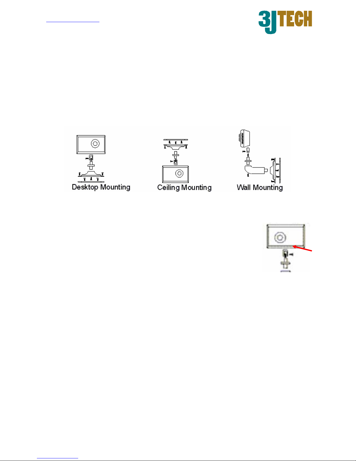
3. Assembling Camera.......................................................................................................10
3.1 Mounting Methods ................................................................................................10
3.2 Outdoor Housings.................................................................................................10
4. Quick Setup / Installing Your Camera Software ............................................................. 11
4.1 Installing Software ................................................................................................ 11
4.2 Modem..................................................................................................................13
4.3 Installing Your Camera..........................................................................................13
5 Application Software provided.........................................................................................14
5.1 CAMit I+ Setup .....................................................................................................15
5.1.1 Setting Parameters.....................................................................................15
5.1.2 Primary Settings .........................................................................................16
5.1.2.1 Advance Settings..............................................................................17
5.1.2.2 Adjust Sensor ...................................................................................18
5.1.3 Security Settings.........................................................................................19
5.1.3.1 Activate Security Functions: .............................................................20
5.1.4 View Images ...............................................................................................21

http://www.3jtech.com.tw
http://www.3jtech.com
CAMit I+gsm
Copyright of 3JTech Co., Ltd. (also doing business as A3J Engineering Inc.)
4
5.1.5 Save and Restart the Camera ....................................................................22
5.2 CAMit I+ Application Software ..............................................................................23
5.2.1 CAMit I plus Camera Site Menu .................................................................23
5.2.1.1 Phonebook List.................................................................................24
5.2.1.2 Site Management .............................................................................24
5.2.2 Connect to a Site ........................................................................................26
5.2.3 Browsing Camera .......................................................................................27
5.2.3.1 Browsing Window.............................................................................27
5.2.3.2 Image Information Display................................................................28
5.2.3.3 Changing Image Size .......................................................................28
5.2.3.4 Change Screen Size.........................................................................28
5.2.4 Remotely Setup the Camera ......................................................................29
5.2.4.1 Primary Setup:..................................................................................29
5.2.4.2 Security Setup ..................................................................................31
5.2.5 Recording Image ........................................................................................33
5.2.5.1 Setup Recording Directory ...............................................................33
5.2.5.2 Recording .........................................................................................34
5.2.5.3 Call Back Recording.........................................................................34
5.2.6 Play Recorded Images ...............................................................................34
5.2.6.1 Delete Recorded Images..................................................................36
5.2.6.2 Save Images into JPG files ..............................................................36
5.2.7 Modem Configurations ...............................................................................37
5.2.8 External Routine .........................................................................................37
5.2.9 Help ............................................................................................................37
6. Frequently Asked Questions: .........................................................................................38
Can I view the same site from different locations? .......................................38
Can I view same site simultaneously from 2 locations?................................38
Why won’t my modem in the camera recognize the dial tone?.....................38
Why won’t my external trigger input work?...................................................38
What should I do if I forget my password?....................................................38
7. Specifications.................................................................................................................39

http://www.3jtech.com.tw
http://www.3jtech.com
CAMit I+gsm
Copyright of 3JTech Co., Ltd. (also doing business as A3J Engineering Inc.)
5
1. Product Overview:
1.1 Introduction
CAMit I+ GSM is a color camera with a built-in modem. This camera is a complete system
by itself, working as a stand-alone viewing center. Further more, with 3JTech’s latest
development, you will be able to connect external GSM modem and make your CAMit I+
camera a complete mobile system.
It can be connected at any regular residential telephone line, or analog PBX extension line,
to transmit live images via phone line. You can also link the device with an external GSM
modem, together with GSM sim cards, you have created a wireless environment for your
CAMit I+. You can dial in the CAMit I+ from any remote location using a computer and a
modem to monitor in real time and record images.
CAMit I+ can also be triggered by its built-in motion detection, normal close to open or other
external TTL level signal devices. Upon trigger, CAMit I+ will automatically dial out and
send images to a remote pre-set computer for recording.
Together with the built-in real time clock, you will be able to schedule the camera for
security mode. Therefore, CAMit I+ will provide you with real 24 hour surveillance system
for maximum security.

http://www.3jtech.com.tw
http://www.3jtech.com
CAMit I+gsm
Copyright of 3JTech Co., Ltd. (also doing business as A3J Engineering Inc.)
6
1.2 Features
9Low cost, DIY remote security camera
9External GSM modem connectable
9NO computer needed at monitored site
9Point to point, modem to modem, real time remote monitoring
9Built-In Real Time clock for scheduled security
9Sensitivity adjustable motion detection, for security purposes
9Trigger In/Out connector for connecting external sensor for monitoring and security
purposes
9Up to 8 external Trigger In/Out upgradeable
9Record images onto hard drive of computer, Jpeg format available
9Password protection
9Small size and low power consumption
9Automatic/Manual gamma correction
9Non aging CMOS image capture device
1.3 Package Content
1) 1 CAMit I+ camera
2) 1 CD with software (CAMit I Setup & CAMit I AP) and user’s manual
3) 1 RJ11 telephone line cord
4) 1 (120 V, 60 Hz) Power adaptor with Trigger In/Out connectors
5) 1 DB9 (RS232) serial connector cable for setup

http://www.3jtech.com.tw
http://www.3jtech.com
CAMit I+gsm
Copyright of 3JTech Co., Ltd. (also doing business as A3J Engineering Inc.)
7
2. Physical Description
The following information contains the physical description of CAMit series camera. This
includes the functions and the locations of each connector and indicator. The information
provides useful reference when installing the product. Please familiarize yourself with
CAMit cameras.
2.1 The Front Panel
Lens
CAMit I box includes a standard 120° wide angle lens fix to the camera. For custom user,
other types of lens are also available upon request. Please note that different price may
occur with different lenses.
Lens

http://www.3jtech.com.tw
http://www.3jtech.com
CAMit I+gsm
Copyright of 3JTech Co., Ltd. (also doing business as A3J Engineering Inc.)
8
2.2 The Back Panel
RS232 Serial Connector
This serial connector provides links between the computer and the camera via RS232. This
connector is used for the computer to configure the camera. The RS232 serial connector is
also used for extension of devices such as external Trigger In/Out, GSM modem etc.
Phone Line Connector
CAMit I+GSM is designed for connection via phone lines and modems, please plug the
phone line here.
Power Supply Connector
CAMit adopts unique RJ22 cable for power supply. The special featured RJ22 cable
includes Input / Output (I/O) function. Simply connect the Input / Output cable to desire
address and no hardware jumper fixing on camera is required.
Serial Number / Firmware version
The label sticker includes the serial number and the Firmware version of the camera.
Note. If you have updated the camera firmware version, the firmware version information
may no longer be valid.
Serial Number
Firmware version
RJ22 Power
Connector
Phone Line
Connector
RS232 Serial Connector

http://www.3jtech.com.tw
http://www.3jtech.com
CAMit I+gsm
Copyright of 3JTech Co., Ltd. (also doing business as A3J Engineering Inc.)
9
2.3 Power Supply Adaptor
Power Point Adaptor
Plug the power point to your local power point. The specifications for the power adaptor are
as follows:
Input: 100 – 240Vac ~ 0.3A 50/60Hz
Output: 5.0Vdc / 2.0A
RJ 22 Camera Point
Plug this end to the camera’s RJ22 slot.
Trigger In / Out Connector
The Trigger In/Out connector cable is connected to the RJ22 AC power adaptor.
Trigger Out
The Red cable is for Trigger Out and it needs to be connected to TTL level (0 – 5 V)
external devices.
Trigger In
The White cable is for Trigger In and it also required to be connected to TTL level (0 – 5 V)
external devices.
Ground
The Ground cable is the black and can be found both on Trigger In and Trigger Out.
Ground
Trigger Out
Trigger In
Trigger In/Out
Connector
RJ22 Camera Point
Power Point Adaptor

http://www.3jtech.com.tw
http://www.3jtech.com
CAMit I+gsm
Copyright of 3JTech Co., Ltd. (also doing business as A3J Engineering Inc.)
10
3. Assembling Camera
The information provided in this section will assist you in assembling and install the product
correctly. It is recommended to configure the camera before positioning the camera.
3.1 Mounting Methods
CAMit I+GSM come with a desktop mount upon purchase. To position the camera, fasten
the camera with screws in the holes at the base of the mount. The default mount
configuration is the desktop mount.
In case of ceiling mount, remove the screws attaching the mount to the
camera and re-attach the mount to the spare hole on the top of the
camera.
Wall mounting leg is optional accessory upon request with additional charge. Please
contact your local dealer for more information.
3.2 Outdoor Housings
CAMit I+GSM cameras are not designed to be outdoor camera. Due to the unexpected
exterior environment, extra housing is required if you wish to install CAMit cameras
outdoors.

http://www.3jtech.com.tw
http://www.3jtech.com
CAMit I+gsm
Copyright of 3JTech Co., Ltd. (also doing business as A3J Engineering Inc.)
11
4. Quick Setup / Installing Your Camera Software
This section will teach you how to setup the camera step by step, including the installation
of application software and using the software to configure the camera.
4.1 Installing Software
1. Place the Application CD into your CD-Rom drive.
2. When the Install window show up, select “Setup CAMit I+ AP” If the window does not
load automatically, please go to my computers and double click on the CD-Rom drive
with installation CD or run the setup.exe file under CAMit I+ directory.

http://www.3jtech.com.tw
http://www.3jtech.com
CAMit I+gsm
Copyright of 3JTech Co., Ltd. (also doing business as A3J Engineering Inc.)
12
3. After selecting “Install CAMit I+GSM” the Install Shield Wizard window should appear
and take you through installing. Please follow the instructions and press Next.
4. The window will then ask you for your user information. Please enter the user
information accordingly.
5. Choose Destination Location – If you wish to change the destination folder for CAMit
I+GSM software, please press browse and select your desired folder else press Next.
6. Start Copying Files – Please click Next to continue or Back to go back to Choose
Destination Location.
7. Please wait while the program is installing.
8. Click Finish when installation is complete.

http://www.3jtech.com.tw
http://www.3jtech.com
CAMit I+gsm
Copyright of 3JTech Co., Ltd. (also doing business as A3J Engineering Inc.)
13
4.2 Modem
Before proceeding with a remote CAMit I+GSM session, your PC should have a modem
installed. Please, refer to your operating system to install and configure your modem.
As a reference, usual modem parameters are to be used with CAMit I+GSM. Most common
ones are the following:
8 bits, no parity, 1 stop bit
Hardware Flow Control, Clear to Send (CTS)
Carrier Detect: ON
Normal DTR Operations
Auto Answer ON if you wish to received a call dialed by a triggered CAMit-I.
(Please refer to your modem user manual for more information on installing the
modem.)
4.3 Installing Your Camera
After you have set up your modem and installed the software we provided. Simply plug the
phone line and the power chord to your camera at the location you with to install. This will
initiate the camera, and should be ready for you to dial in!

http://www.3jtech.com.tw
http://www.3jtech.com
CAMit I+gsm
Copyright of 3JTech Co., Ltd. (also doing business as A3J Engineering Inc.)
14
5 Application Software provided
Before getting started with the CAMit I+GSM, you should have already installed the
software programs (CAMit I+ Setup, CAMit I+ AP and Image Player) and downloaded this
user’s manual from the CD provided in the package.
The CAMit I+ Setup are used to setup the parameters of the camera. It needs to be
connected to the camera using a PC via a serial port. To do so, a DB9 RS232 serial cable is
provided from the package.
The CAMit I+ AP is the application software to communicate with the CAMit I+GSM
remotely. Please read this user’s manual thoroughly to understand the functions and
capabilities of the CAMit I+GSM camera.

http://www.3jtech.com.tw
http://www.3jtech.com
CAMit I+gsm
Copyright of 3JTech Co., Ltd. (also doing business as A3J Engineering Inc.)
15
5.1 CAMit I+ Setup
You will be able to set up your CAMit I+GSM directly off your computer. Please note that
this is not necessary as you will be able to set up all the necessary functions remotely.
First, please connect your CAMit I+GSM to a PC using the DB9 (RS232) cable included.
You may also download new softwares from http://www.3jtech.com/Downloads.htm web
site.
Start the CAMit I+ Setup Application. After
selecting the correct com port with valid
connections between PC and CAMit I+GSM, you
will be able to begin setting the parameters of
CAMit I.
5.1.1 Setting Parameters
You will be able to select 2 different sections for the setup; the Primary Settings and the
Security Settings. You will be able to set up all the necessary parameters which are
camera related in the Camera Setting. On the other hand, Security Setting will allow you
to setup the security functions of your CAMit I+GSM camera.

http://www.3jtech.com.tw
http://www.3jtech.com
CAMit I+gsm
Copyright of 3JTech Co., Ltd. (also doing business as A3J Engineering Inc.)
16
5.1.2 Primary Settings
Here are the use and the description for each parameter in Camera Settings.
Camera Name:
Here you will be able to name you Camera Site, which it will display when you establish
connection with the camera. Simply enter the desire name you wish for up to 24 characters
and numbers.
Camera Password:
You can set the password to your camera. It will protect others from accessing your camera.
Simply enter the desire password with any combination of characters and numbers up to 24
characters.
Country Code:
The country code is the section where you will be able to select the country the camera is
set. This is used because different country has slightly different dial tone. 3JTech has
adjusted the camera to suit each individual environment. Simply select your country from
the list.
Number of ring to wait before answering:

http://www.3jtech.com.tw
http://www.3jtech.com
CAMit I+gsm
Copyright of 3JTech Co., Ltd. (also doing business as A3J Engineering Inc.)
17
This is where you can set your camera to pick up after certain rings. E.g. If you set it to 3,
the camera will pick up the call after 3 ringing tones were detected. To set the number,
please enter the number of rings at the text box below.
Camera Serial Number:
This section will display the serial number for the camera.
Camera Firmware Version:
This section will display the firmware version of the
camera.
5.1.2.1 Advance Settings
In Advance settings, the parameters are not
necessary required for the running of CAMit I+GSM.
It is other optional parameters, you may set for your
camera.
Use GSM Modem:
You can choose to use an external GSM modem as
the method of connection. To enable this function,
please check the check box before the description.
Note. You will need to reset the camera to initiate this function. The camera will reset itself
after you update the information. Please wait for at least 1 minutes before try and connect
to you camera.
Camera’s Date:
This section will show you how to set up the real time clock for your camera. The clock in
your camera is an individual clock, and is not related to your computer time.
Synchronize with PC’s Date/Time:
Enable this function will allow the camera time to be synchronized with the computer.
To enable it, please check the check box.
Camera Date (mm/dd/yyyy):
This section will allow you to set the date in the camera. Please insert the date you
wish to set to the according text boxes. (Months/Date/Year and Day)
Camera Time (hh:mm:ss):
This section will allow you to set the time in the camera. Insert the time you wish to set

http://www.3jtech.com.tw
http://www.3jtech.com
CAMit I+gsm
Copyright of 3JTech Co., Ltd. (also doing business as A3J Engineering Inc.)
18
to the corresponding boxes. (Hour/Minutes/Seconds)
Note. Time synchronization will not take effect until you click on save button.
5.1.2.2 Adjust Sensor
Adjust Images
To adjust the settings of the images please click on Configure button. A window should
load when click. You will able to adjust the different variables such as brightness, contrast,
saturation, sharpness, hue, backlight and exposure of the camera by drag the scroll bar left
and right. Click on Auto will allow the camera to do automatic adjustments. Click Exit when
done.

http://www.3jtech.com.tw
http://www.3jtech.com
CAMit I+gsm
Copyright of 3JTech Co., Ltd. (also doing business as A3J Engineering Inc.)
19
5.1.3 Security Settings
This section contains all the necessary parameters for you to set the security function which
comes with your CAMit I+GSM cameras.
Enable motion detection:
This is the built-in motion detection that came alone with the camera. To enable it, please
check the box.
Sensitivity:
You can choose between 3 different sensitivities to
suit your purpose. Please select one of the 3
options from “High”, “Mid”, and “Low.”
Trigger In Settings:
Here you will be able to enable the trigger in function for
your camera. Please check the trigger in box you wish
to enable it.
Device 1 of Trigger In is the default device that came
with the camera, the wiring for it is set to be normal
close. Device 2 to 9 is only available if you have
installed the external trigger device with your camera.
You will be able to choose the wiring of the device, to open or close accordingly.

http://www.3jtech.com.tw
http://www.3jtech.com
CAMit I+gsm
Copyright of 3JTech Co., Ltd. (also doing business as A3J Engineering Inc.)
20
Note. The Following Functions will only be available when Either Motion Detection of
Trigger In is enabled.
5.1.3.1 Activate Security Functions:
Guard Mode Always:
If you chose always, the security function such as
motion detection or trigger in will be on at all
times.
Scheduled Guard Mode:
Check this box will allow you to schedule the camera to set itself into alert mode
automatically. The camera will automatically turn on its Trigger In and Motion Detection if it
is set, at the corresponding time set by you.
Please insert the time accordingly to the text boxes. It operates with 24 hour time and
depend on the real time clock built-in the camera. For more information regarding to setting
up the real time clock please refer to the Camera’s Date section.
Number of Images Send:
This will let you configure the number of
pictures for the camera to send when it is
triggered. Simply enter up to maximum of
20 picture you wish the camera to send
when it is triggered.
Picture Sizes:
You can choose the size of the picture to be sent. There are 3 different sizes to chose
from; 640x480, 320x240, 160x120. Please select one of the 3 options.
Call Back Parameters:
This section includes the necessary
parameters for call back setup after the
camera is triggered.
Number of Times to Attempt:
This is the number of time which the
camera will try to call back to the remote
Table of contents