7
TECHNICAL MANUAL ICM 3L.P. GAS s.r.l.
3.0 ACCESSORIES
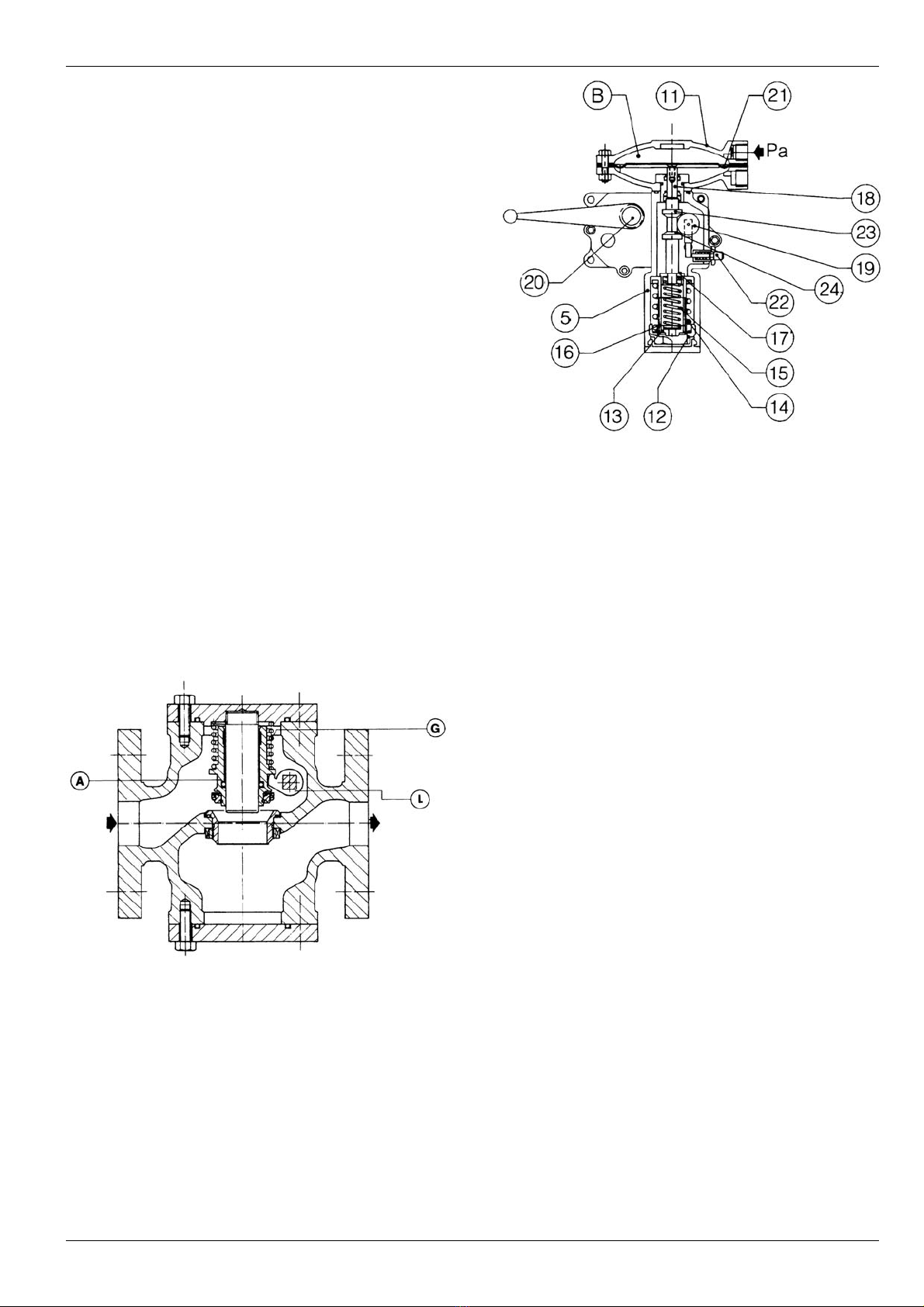
3.1 “PUSH” THREE-WAYS SWITCH VALVE
(FIG. 8)
The “Push” is a special spring three-ways switch val-
ve. When the knob is in the “rest” position, the angular
A and B ways are in comunication while the C way is
excluded. With the knob pressed down in the “check”
position, the A and C way are connected and the B
way excluded. When thrust is taken off the knob, the
connection between A and C is AUTOMATICALLY
REESTABLISHED by means of the spring pos. 11.
With the steam in the middle “open” position, the three
ways are all in communication with each other. This
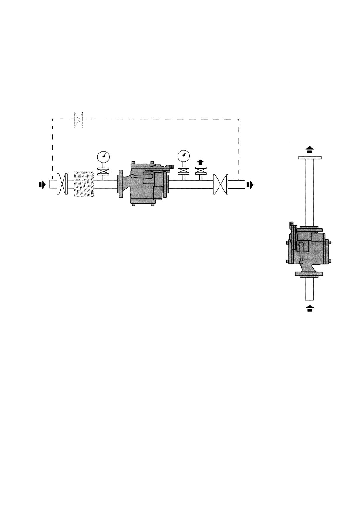
cock is normally installed in the impulse lines of safety
devices for protection against pressure increases and/
or decreases (SAV and SBV) in order to allow very
rapid verification of the settings without disconnec-
ting the impulse pipes themselves during periodical
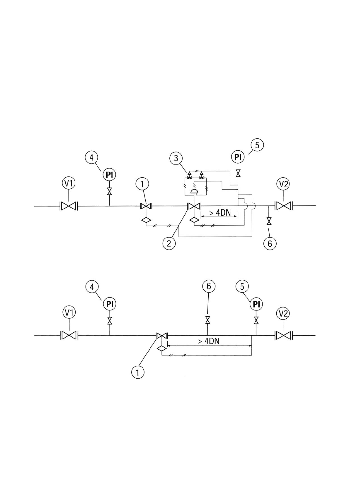
checking operations. Its particular feature lies in the
fact that, during normal running, the head (or the pilot
of safety valve) receives the signal of the pressure to
be kept under control through the A and B ways; when
testing, the head receives the signal of a CONTROL-
LED PRESSURE from the A and C ways; once the
check has been carried out, when the knob returns to
the “rest” position, the connection is automatically re-
established between the safety device head and the
environment with the pressure to be controlled, thus
avoiding the risk to shut off the safety device itself as
it would in the case of a normal, manually-operated
threeway cock, due to a trivial oversight. In other
words, the “Push” is a SECOND SAFETY DEVICE
which ensures the NON EXCLUSION of the main
safety device and allows for its “Fool-proof”
PERIODICAL CHECKING.
The stem is fitted with a stroke limit pin which makes
it possible to:
- connect A and C ways only when the pin enters the
“check” slot;
- connect the three ways, a, B and C, when the pin is
on “open”.
4.0 START UP
4.1 GENERAL
After installation, check that the inlet/outlet on/off
valves, any by-pass and the bleed cock are closed.
Before commissioning, you must ensure that the
conditions of use comply with the characteristics of
the apparatuses.
These characteristics are recalled by the symbols on
the specification plates applied to each apparatus.
We recommend actuating the opening and closing
valves very slowly. The valve could be damaged by
operations which are too fast.
APPARATUS SPECIFICATION PLATES
The list of symbols used and their meanings are listed
below:
Pemax = maximum operating pressure at the inlet of
the apparatus
Pzul = maximum pressure which can be supported by
the structure of the body of the apparatus in safety
conditions
AG = intervention accuracy
Wao = range of intervention for the over pressure of
slam-shut, relief and safety valves and accelerators
which can be obtained using the setting spring fitted
at the moment of testing. In piloted safety valves, the
pilot is considered as a separate apparatus with its
own setting range Wao
Who = range of intervention for the over pressure of
slam-shut, relief and safety valves and accelerators
which can be obtained using the setting springs
indicated i the tables. In piloted safety valves, the pilot
is considered as a separate apparatus with its own
setting range Who
Wau = range of intervention for pressure decrease of
sla-shut which can be obtained using the setting
springs indicated in the tables.
Fig. 8