3M FDTC 08S User manual

June 2012
78-8135-6188-9-D 3
3M™Fiber Dome Terminal Closure
FDTC 08S Direct Splice
3M™Fiber Dome Closure FDC 08S-A
Instructions
1.0 Introduction
The 3M™Fiber Dome Terminal Closure FDTC 08S
(Direct Splice) or 3M™Fiber Dome Closure FDC 08S-A
can accommodate up to eight 0.47" (12 mm) cables when
using the 3 mm external cable assembly module (ECAM)
and two 0.79" (20 mm) main cables. The 3M™External
Cable Assembly Module (ECAM) Cable Entry Port Kit is
designed to accept fiber optic loose tube and central tube
cables with external diameters from 0.16" to 0.47" (4–12
mm) and flat drop 0.18" x 0.32". It will accommodate
cables with single or dual cable strength members. The
FDTC 08S direct splice can accommodate both dielectric
and armored drops and cables. For armored cables, the
grounding kit must be purchased separately.
Specifications
Item Qty. Description
Tray Capacity 43M™Fiber Optic Splice Trays
2538
Splice Tray Capacity 24
72
12
Single Fusion (Double Stacked)
Mass Fusion
3M™Fibrlok™ Splices
Max Drops/Branch Cables 80.16" (4 mm) min to 0.47"
(12 mm) max diameter
Main Cables 20.39" (10 mm) min to 0.79"
(20 mm) max diameter
Ground Lugs 0 or 1
Air Valve 5.8 PSI (40 kPa) max flash
Express Storage 72" (1.8 m) max of LBT 72F
(12 fibers/buffer)/RF 144F
2.0 Kit Contents
A. Dome
B. Band
C. Storage tray
D. Base assembly
E. 3M™Double Cable Entry Port External Cable
Assembly Module ECAM-20MM-D
F. Double Cable Entry Port ECAM-20MM-D loose
parts
G. (1) 3M™Fiber Optic Splice Tray
2538-24-DF/72-MF
H. Double Cable Entry Port ECAM-20MM-D
Instructions
I. Fiber Dome Terminal Closure FDTC 08S and
Fiber Dome Closure FDC 08S-A Instructions
A
B
D
E
F
C
G

2 78-8135-6188-9-D
3M™Fiber Optic Splice Tray 2538
A. Splice tray
B. Tray cover
C. (2) 3M™Single Fusion Spice Holder 2521-F
D. (1) 3M™Ribbon Spice Holder 2521-FL
E. Label
F. Cable ties
G. Rubber gripper
A
B
G
D
E
F
C
Visually inspect all components. If any component is
missing or appears damaged, do not install. Call customer
service at 1-800-426-8688 for a replacement product.
3.0 3M™Fiber Dome Terminal Closure
FDTC 08S (Direct Splice) and
3M™Fiber Dome Closure FDC
08S-A Base Configuration
1
234
5
67
8
Ground Stud
1/4-20 Thread
Air Valve
3M™Double Cable Entry Port
ECAM-20mm-D
4.0 3M™Double Cable Entry Port
External Cable Assembly Module
ECAM-20 mm-D Preparation
4.1 Refer to instruction manual 78-8140-3820-3,
3M™Double Cable Entry Port ECAM-20mm-D
for cable seal preparation included in kit.
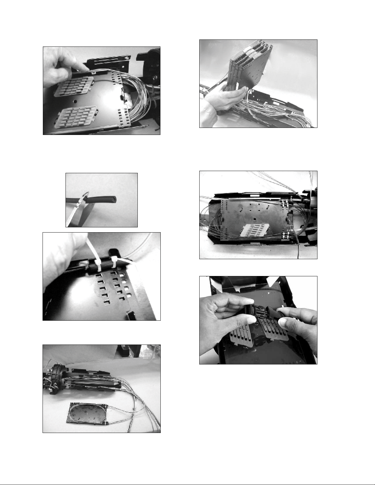
5.0 Fiber Slack Storage
5.1 Determine buffer tube or ribbon to be cut and
cut at appropriate end for splicing.
5.2 Store remaining express fiber slack as shown.
Do not exceed minimum bend radius.
Loose Buffer Tube
Step 1 Step 2 Step 3
Ribbon
5.3 Using cable ties, secure the central tube in the
storage tray as shown.

378-8135-6188-9-D
6.0 Cable Splicing
6.1 Determine type of splice insert needed. 3 mm
diameter fusion sleeves (3M™Fusion Sleeves
2170) are recommended. Smaller diameter
sleeve may require the use of RTV to aid in
retention.
3M™Discrete Fusion 2521-F
3M™2521-FL Mass Fusion and 3M™Fibrlok™ Splices
6.2 Install splice insert into splice tray by slipping
tabs under metal retainers as shown.
6.3 Attach splice log decal to cover.
Note: Bottom portion of decal can be cut off and used
to identify individual trays.
6.4 Place splice tray in storage tray. Tabs on tray
nest between tabs in storage tray.
6.5 If needed, tray can be held in storage tray by
using a cable tie as shown.
6.6 Loosen Buffer Tube
6.6.1 Fiber slack can be store in tray as shown.
4 78-8135-6188-9-D
6.6.2 Route fiber into splice tray to determine
amount of buffer tube to remove. Remove
buffer tube and clean fiber as required.
6.6.3 Cut a one-inch (25 mm) long section of
the rubber gripper supplied with the splice
tray kit and use to secure buffer tubes or
ribbon fiber (up to six ribbons) to tray.
6.6.4 Buffer tube splicing can be done with the
splice tray removed from the storage tray.
6.6.5 Up to four 3M™Fiber Optic Splice Trays
2538 can be stacked in closure.
6.7 Ribbon
6.7.1 Recommend ribbon splicing be done
with the splice tray mounted inside the
storage tray.
6.7.2 Secure tray(s) by attaching retaining strap.
578-8135-6188-9-D
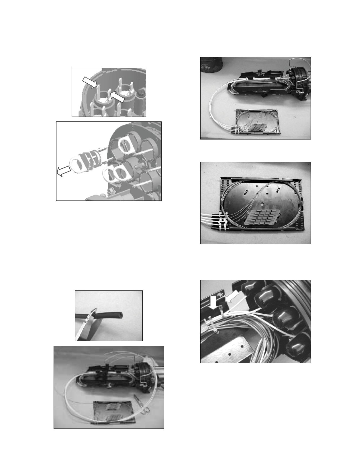
7.0 Drop Port Installation
7.1 Clean any dirt from port in base.
7.2 Determine drop entry port and remove plug by
squeezing tabs together inside base. At the same
time pull ring outward.
7.3 Lightly lube both the O-ring seal area base
port and the 3M™External Cable Assembly
Module (ECAM) Port O-ring using the supplied
lubricant.
Note: Follow health, safety and environmental
information. Refer to product label or Material Safety
Data Sheet for silicone lubricant.
7.4 Cut a one-inch (25 mm) long section of the
rubber gripper supplied with the splice tray kit
and use to secure buffer tubes or ribbon fiber to
tray.
7.5 Splicing can be done with the splice tray
mounted inside the storage tray (recommended
for ribbon splicing) or can be removed as
shown. Route drops into tray to determine
amount of buffer tube to be removed.
7.6 Drops number one to four can be routed as
shown.
7.7 Route drops as shown. Cable tying groups of
buffer tubes together reduces the chance of
kinking the buffer tubes. Secure stored fiber as
needed using cable ties.

6 78-8135-6188-9-D
7.8 To add drop number five through eight
temporarily place the splice tray into the storage
tray and route remaining drop(s) as shown.
Mark tray entry point on buffer tubes.
7.9 Splicing of remaining four drops can be done
outside if desired.
7.10 Example of routing of drops.
7.11 Secure tray(s) by re-attaching retaining strap.
8.0 Closure Sealing
8.1 Ensure both the dome seal area and base O-ring
is free of dirt or any damage. If needed clean
area and apply a light film of supplied silicone
lubricant. Failure to maintain a clean seal area
may lead to leakage.
Note: Follow health, safety and environmental
information and refer to product label or Material Safety
Data Sheet for silicone lubricant.
8.2 Clean and lubricate cable ties, O-ring.
8.3 Replace the dome and engage latch over dome
ear as shown.
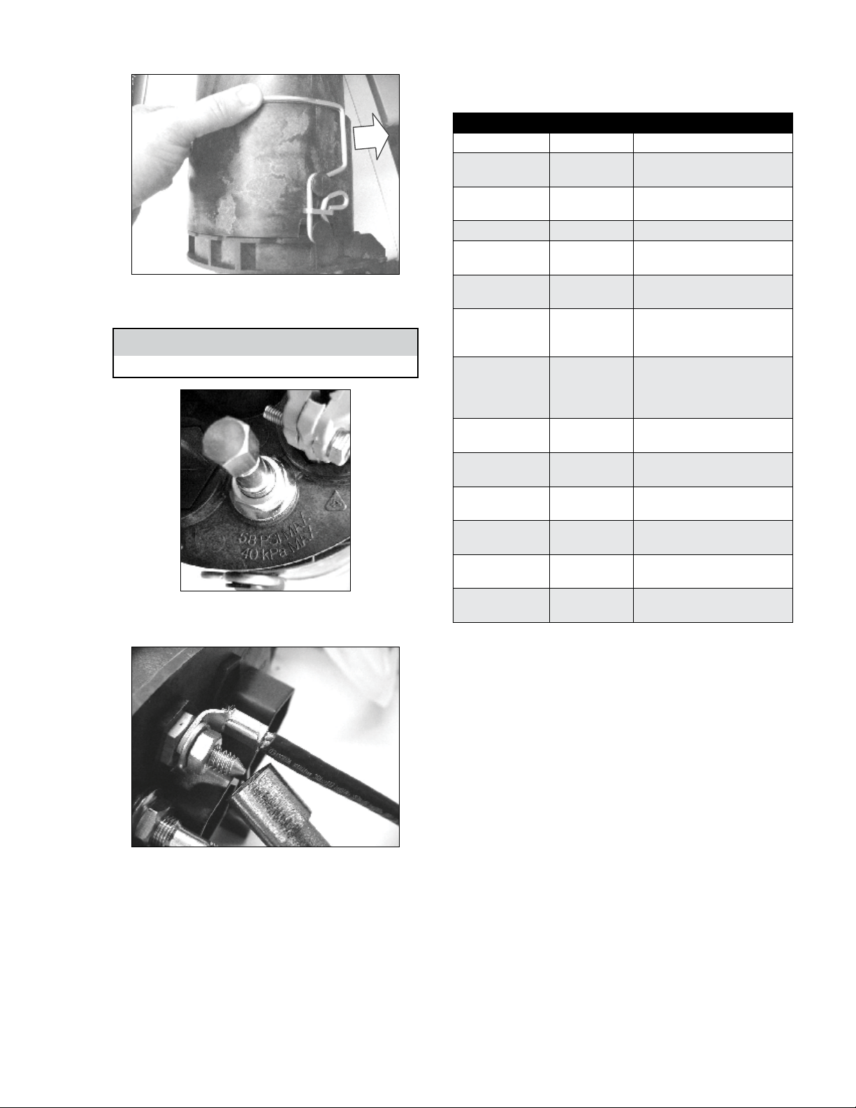
778-8135-6188-9-D
8.4 Fully close latch to seat dome onto the base.
8.5 Assembled unit can be flash tested at 5.8 PSI
max (40 kPa max).
Caution
Vent pressure after flash testing.
8.6 External grounding can be added to ground lug
on base.
9.0 3M™Fiber Dome Terminal FDT08
Accessories
Product Number 3M ID Description
ECAM-12MM 80-6113-1696-1 12MM ECAM CABLE ENTRY PORT
ECAM-20MM-D 80-6113-2951-9 20MM DOUBLE CABLE ENTRY
PORT, US
ECAM-GND-6-AWG 80-6113-1702-7 ECAM (18, 20, 27MM) CABLE GND
(6 AWG)
ECAM-GND-14-AWG 80-6113-1704-3 ECAM CABLE GND (14 AWG)
FD-08-HH-1730 80-6113-1706-8 FD08 HANDHOLE MOUNTING
BRACKET FOR 17 X 30
FD-08-AERIAL-SHB 80-6113-1707-6 FD08 AERIAL STRANDMOUNT
HANGER BRACKET
FDST/FDT-08M-
AERIAL-SHB 80-6113-3206-7
AERIAL STRAND MOUNT HANGAR
BRACKET FOR FDST08 AND
FDT08M
FDST/FDT-08-POLE/
PED-HB 80-6113-3205-9
POLEMOUNT, WALMOUNT, BD4,
BD5, CHNL MAH100 PEDMOUNT
BRKT FOR FDST08, FDT08, FDT08M
AND FDT08S
2538-24-DF/72-MF 80-6113-1714-2 2538 F/O SPLTRAY 24 DISCRETE/72
MASS FUSION
2539-12-DF 80-6113-1715-9 2539 F/O SPLICE TRAY 12
DISCRETE FUSION SPLICES
2540-12-DF/36-MF 80-6113-1716-7 2540 F/O SPL TRAY 12
DISCRETE/72 MASS FUSION
FDT-08-PED-CH 80-6113-1720-9 FD08 PED MOUNTING BRACKET
FOR 10” CHANNEL PED
FDT-08-PED-CI 80-6113-1721-7 FD08 PED MOUNTING BRACKET
FOR 8” CHARLES IND PED
2518 80-6113-2634-1 LBT FIBER 2MM TRANSITION TUBE
KIT

3M and Fibrlok are trademarks of 3M Company.
Important Notice
All statements, technical information, and recommendations related to 3M’s products are based on information believed to be reliable, but the accuracy or
completeness is not guaranteed.Before using this product, you must evaluate it and determine if it is suitable for your intended application.You assume all risks
and liability associated with such use.Any statements related to the product which are not contained in 3M’s current publications, or any contrary statements
contained on your purchase order shall have no force or effect unless expressly agreed upon, in writing, by an authorized officer of 3M.
Warranty; Limited Remedy; Limited Liability.
This product will be free from defects in material and manufacture for a period of one (1) year from the time of purchase. 3M MAKES NO OTHER
WARRANTIES INCLUDING, BUT NOT LIMITED TO, ANY IMPLIED WARRANTY OF MERCHANTABILITY OR FITNESS FOR A PARTICULAR PURPOSE.
If this product is defective within the warranty period stated above, your exclusive remedy shall be, at 3M’s option, to replace or repair the 3M product
or refund the purchase price of the 3M product. Except where prohibited by law, 3M will not be liable for any indirect, special, incidental or
consequential loss or damage arising from this 3M product, regardless of the legal theory asserted.
3
Communication Markets Division
6801 River Place Blvd.
Austin, TX 78726-9000
1-800-426-8688
www.3M.com/Telecom
Please Recycle. Printed in USA.
© 3M 2012. All Rights Reserved.
78-8135-6188-9-D
Other manuals for FDTC 08S
1
This manual suits for next models
1
Table of contents
Other 3M Network Hardware manuals


Popular Network Hardware manuals by other brands

Matrix Switch Corporation
Matrix Switch Corporation MSC-HD161DEL product manual

B&B Electronics
B&B Electronics ZXT9-IO-222R2 product manual

Yudor
Yudor YDS-16 user manual

D-Link
D-Link ShareCenter DNS-320L datasheet

Samsung
Samsung ES1642dc Hardware user manual

Honeywell Home
Honeywell Home LTEM-PV Installation and setup guide


