3One data IAP2600S Series User manual

IAP2600S Series
Industrial Dual-band Wireless AP
Quick Installation Guide
3onedata Co., Ltd.
Address: 3/B, Zone 1, Baiwangxin High Technology
Industrial Park, Xili, Nanshan District, Shenzhen
Website: www.3onedata.com
Tel: +86 0755-26702688
Fax: +86 0755-26703485
【Package Checklist】
Please check whether the package and accessories are intact
while using the dual-band wireless AP for the first time.
1.
Wireless AP x1
2.
Pole/wall mounting attachment
3.
PoE adapter
4
Warranty card
5.
Certification
If any of these items are damaged or lost, please contact our
company or dealers, we will solve it ASAP.
【Product Overview】
The product is a managed industrial dual-band wireless AP.
Models as follows:
Model I. IAP2600S-4A25-5GT-PD (1 Gigabit PoE copper
WAN port + 4 Gigabit copper LAN ports + 2 2.4G
antenna interfaces + 2 5.8G antenna interfaces +
48VDC POE power supply)
Model II. IAP2600S-4A25-1GC3GT-PD (1 Gigabit PoE
Combo WAN port + 3 Gigabit copper LAN ports + 2
2.4G antenna interfaces + 2 5.8G antenna
interfaces + 48VDC POE power supply)
【Panel Design】
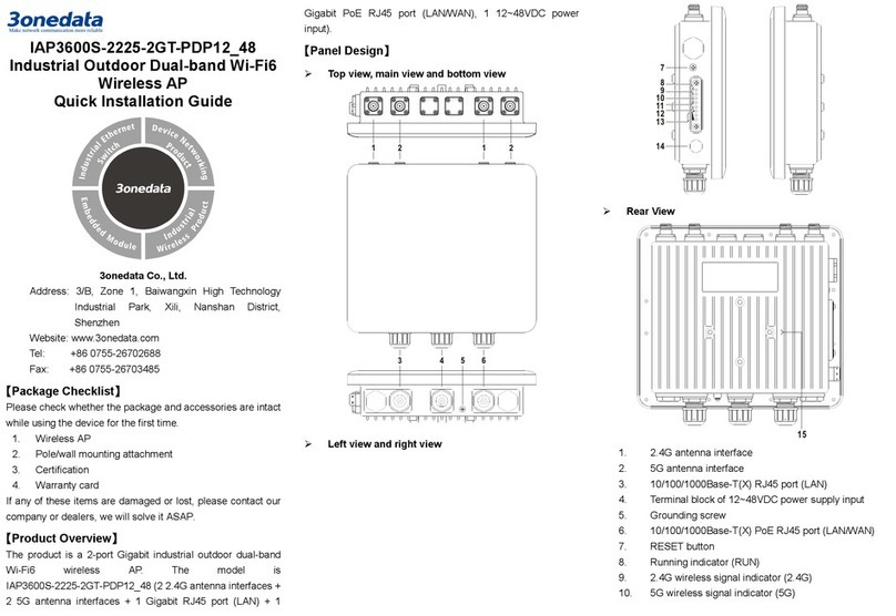
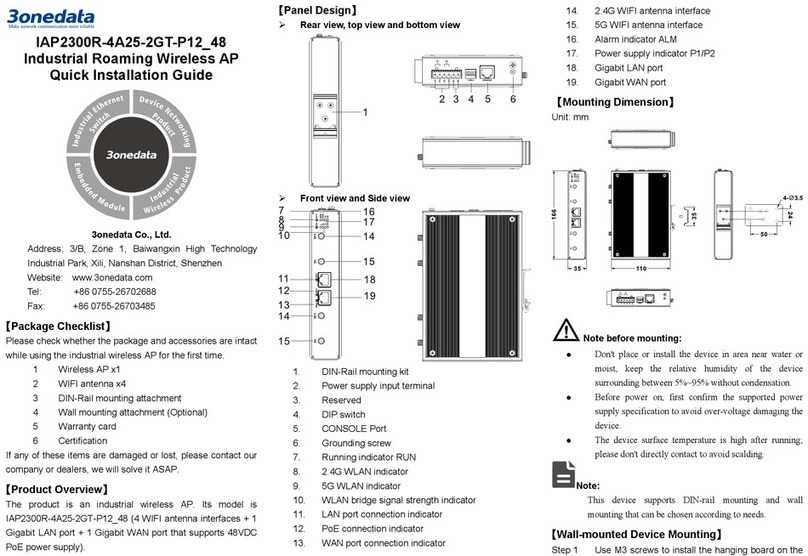
Top view and front view
Model I
Model II
Bottom view and rear view
Model I
Model II
Left view
Right view

Model I
Model II
1. Console port
2. Reset button
3. Running indicator
4. 2.4G signal indicator
5. 5.8G signal indicator
6. WAN indicator
7. LAN indicator 1-3/4 (Green)
8. Breather valve
9. Signal intensity indicator 2-4 or 1-3 (Blue)
10. Wall-mounting location hole
11. 5.8G omnidirectional antenna interface
12. 2.4G omnidirectional antenna interface
13. 10/100/1000Base-T(X) copper LAN port
14. 10/100/1000Base-T(X) copper WAN port (PoE
input)
15. 10/100/1000Base-T(X) Combo WAN port (PoE
input)
【Mounting Dimension】
Unit: mm
Notice before mounting:
Don't place or install the device in area near water or
moist, keep the relative humidity of the device
surrounding between 5%~95% without condensation.
Before power on, first confirm the supported power
supply specification to avoid over-voltage damaging the
device.
The device surface temperature is high after running;
please don't directly contact to avoid scalding.
【Pole-mounted Device Mounting】
Step 1. Use 4 M6 screws to install the clamp board as
shown in the figure below on the device backboard.
Step 2. Align the other clamp board with the hole center
line of the installed clamp board, then place the
support pipe to align the hole center of the two
clamp boards. When the two clamps are docking, it
can choose 15° or 90° installation angle.
Step 3. Pass the M6 long screw through the hole where the
clamp boards are docked and the support pipe, and
tighten the corresponding M6 nut.
Step 4. Install U-shaped derrick screws and derrick teeth
on the clamp board, and put the derrick with a
diameter of Ф40mm-Ф50mm in a U-shaped slot, as
shown in the figure below.
Step 5. Adjust device position and tighten the derrick nut to
fix the position of the device on the derrick.
Installation ends.

【Pole-mounted Device Disassembling】
Step 1. Device power off.
Step 2. Stabilize the device, unscrew the U-shaped derrick
nut and take out the U-shaped derrick screw.
Step 3. Take out the device, disassembling ends.
【Wall-mounted Device Mounting】
Step 1. Use 4 M6 screws to install the clamp board as
shown in the figure below on the device backboard.
Step 2. Align the other clamp board with the hole center
line of the installed clamp board, then place the
support pipe to align the hole center of the two
clamp boards. When the two clamps are docking, it
can choose 15° or 90° installation angle.
Step 3. Pass the M6 long screw through the hole where the
clamp boards are docked and the support pipe, and
tighten the corresponding M6 nut.
Step 4. Pass the M6 screw through the location hole of the
clamp board. The size of location hole of the clamp
board is as shown below.
Step 5. Install the device on the wall and tighten the screw.
Installation ends.
【Wall-mounted Device Disassembling】
Step 1. Device power off.
Step 2. Hold the device steadily and screw out the screw
on the wall.
Step 3. Take out the device, disassembling ends.
【Power Supply Connection】
The WAN port of this device supports standard 48V PoE
power supply, which conforms to IEEE802.3af/at standard.
【Reset Button Setting】
This device provides 1 reset button, press the button
for 1-2S then release it to reboot the device; press the
button for 5S then release it to restore factory defaults.
【Checking LED Indicator】
The device provides LED indicators to monitor the device
working status with a comprehensive simplified
troubleshooting; the function of each LED is described in the
table as below:
LED
Indicate
Description
RUN
ON
The device is running abnormally
OFF
The device is powered off, being
powered on or the device is
abnormal.
Blinking
The device is running normally
5.8G
ON
5.8G wireless signal is running
normally
Blinking
5.8G wireless signal is
transmitting data. The blinking
frequency shows the rate of data
transmission
OFF
5.8G wireless signal is running
abnormally or turned off
2.4G
ON
2.4G wireless signal is running
normally
Blinking
2.4G wireless signal is
transmitting data. The blinking
frequency shows the rate of data
transmission
OFF
2.4G wireless signal is running
abnormally or turned off
WAN
ON
WAN port has established valid
network connection
Blinking
WAN port is in network active
status
OFF WAN port hasn't established valid
network connection
1-3/4
(Green)
ON
LAN port has established valid
network connection
Blinking
LAN port is in network active
status
OFF
LAN port hasn't established valid

LED
Indicate
Description
network connection
(Blue)
Under bridge or client mode,
all indicators are off, it
represents that opposite
terminal wireless signal is
weak or without signal
In dual-
link mode, if the
indicators are off, it means
the two links are
disconnected
Under the bridge or client
mode, it represents that
opposite terminal wireless
signal is weak;
In dual-link mode, it means
that the first link has
established connection and
the second link has no
connection.
In dual-link mode, it means that
the second link has established
connection and the first link has
no connection.
Under the bridge or client
mode, it represents opposite
terminal wireless signal
intensity is general;
In dual-link mode, it means
the two links has established
connection.
Under the bridge or client mode,
all indicators are on, it represents
that opposite terminal wireless
signal is strong
Notes:
In dual-link mode, the definition of indicator signal
strength is as follows:
-Always on: wireless signal is strong;
-0.5/S blink once: wireless signal is normal;
-1.5/S blink once: wireless signal is weak;
In AP and routing mode, indicators 2-4 are LAN
indicators in green; In bridge, client, and dual-link mode,
indicators 2-4 are signal strength indicators shown in
blue.
【Specification】
Standard
Standard IEEE802.3, IEEE802.3u,
IEEE802.11b/g/n/a/ac,
IEEE802.11i, IEEE802.11r,
IEEE802.3af/at
Protocol TCP/IP, DHCP, PPPOE, ICMP,
ARP, HTTP
Interface
WAN 1 10/100/1000Base-T(X)
RJ45port, support POE 48VDC
input power supply;
1 Gigabit Combo port,
supports dual-fiber LC flange
interface or 10/100/1000
Base-T(X) RJ45 port, and
copper port supports POE
48VDC power supply input;
LAN 3/4 10/100/1000Base-T(X) RJ45
ports
Antenna 2 2.4G N-K type (Female) ports
2 5.8G N-K type (Female) ports
Transmission Speed
802.11n
6.5~300Mbps
802.11b
11/5.5/2/1Mbps
802.11g/a
54/48/36/24/18/12/9/6Mbps
802.11ac
65Mbps~867Mbps
Radio Frequency
Channel 802.11b/g/n:
2.412GHz~2.4835GHz
802.11ac/n/a:
5.18GHz-5.825GHz
RF power output
20dBm
Modulation scheme DBPSK, DQPSK, CCK, OFDM,
16-QAM, 64-QAM
Receiving sensitivity
802.11n_HT40 -82dBm@MCS0,
-64dBm@MCS7
802.11n_HT20 -85dBm@MCS0,
-67dBm@MCS7
802.11g/a -91dBm@6Mbps,
-72dBm@54Mbps
802.11b -93dBm@1Mbps,
-87dBm@11Mbps
802.11ac -84dBm@MCS0,
-59dBm@MCS9
Transmitting power
802.11n_HT40
20dBm@MCS0, 20dBm@MCS7
802.11n_HT20
20dBm@MCS0, 20dBm@MCS7
802.11g/a 20dBm@6Mbps,
20dBm@54Mbps
802.11b 20dBm@1Mbps,
20dBm@11Mbps
802.11ac
20dBm@MCS0, 20dBm@MCS9
Power Supply
Input power supply POE 48VDC: support
IEEE802.3af/at standard
Indicator 5.8G signal indicator, 2.4G signal
indicator, WAN indicator, LAN
indicator, running indicator,
signal strength indicator
Power Consumption
No-load
5.4W@48VDC
Full-load
10.2W@48VDC
Working Environment

Working temperature
-40~75℃
Storage temperature
-40~85
℃
Working humidity
5%
~
95% (no condensation)
Protection grade
IP68(metal shell)
This manual suits for next models
2
Table of contents
Other 3One data Wireless Access Point manuals
Popular Wireless Access Point manuals by other brands

Siemens
Siemens SCALANCE W700 Reference manual

Cisco
Cisco AIR-AP1020 - 1000 Series Lightweight Access... quick start guide

HP
HP E-MSM466 Product End-of-Life Disassembly Instructions

MikroTik
MikroTik Groove 2Hn user manual

Clarinet Systems
Clarinet Systems EtherUSB user manual

TP-Link
TP-Link Auranet Series user guide