manuals.online logo
Brands
  1. Home
  2. •
  3. Brands
  4. •
  5. 3One data
  6. •
  7. Wireless Access Point
  8. •
  9. 3One data IAP2300R-4A25-2GT-P12 48 User manual

3One data IAP2300R-4A25-2GT-P12 48 User manual

IAP2300R-4A25-2GT-P12_48
Industrial Roaming Wireless AP
Quick Installation Guide
3onedata Co., Ltd.
Address: 3/B, Zone 1, Baiwangxin High Technology
Industrial Park, Xili, Nanshan District, Shenzhen
Website: www.3onedata.com
Tel: +86 0755-26702688
Fax: +86 0755-26703485
【Package Checklist】
Please check whether the package and accessories are intact
while using the industrial wireless AP for the first time.
1
Wireless AP x1
2
WIFI antenna x4
3
DIN-Rail mounting attachment
4
Wall mounting attachment (Optional)
5
Warranty card
6
Certification
If any of these items are damaged or lost, please contact our
company or dealers, we will solve it ASAP.
【Product Overview】
The product is an industrial wireless AP. Its model is
IAP2300R-4A25-2GT-P12_48 (4 WIFI antenna interfaces + 1
Gigabit LAN port + 1 Gigabit WAN port that supports 48VDC
PoE power supply).
【Panel Design】
Rear view, top view and bottom view
Front view and Side view
1. DIN-Rail mounting kit
2. Power supply input terminal
3. Reserved
4. DIP switch
5. CONSOLE Port
6. Grounding screw
7. Running indicator RUN
8. 2.4G WLAN indicator
9. 5G WLAN indicator
10. WLAN bridge signal strength indicator
11. LAN port connection indicator
12. PoE connection indicator
13. WAN port connection indicator
14. 2.4G WIFI antenna interface
15. 5G WIFI antenna interface
16. Alarm indicator ALM
17. Power supply indicator P1/P2
18. Gigabit LAN port
19. Gigabit WAN port
【Mounting Dimension】
Unit: mm
Note before mounting:
Don't place or install the device in area near water or
moist, keep the relative humidity of the device
surrounding between 5%~95% without condensation.
Before power on, first confirm the supported power
supply specification to avoid over-voltage damaging the
device.
The device surface temperature is high after running;
please don't directly contact to avoid scalding.
Note:
This device supports DIN-rail mounting and wall
mounting that can be chosen according to needs.
【Wall-mounted Device Mounting】
Step 1 Use M3 screws to install the hanging board on the
device backboard.
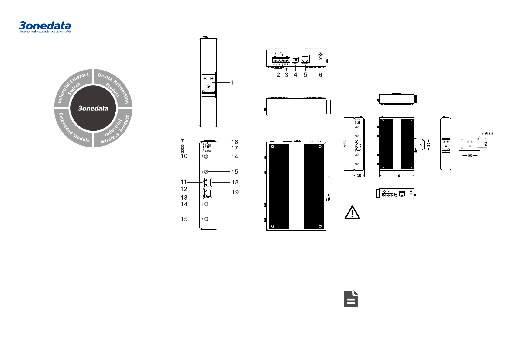
Step 2 Place the device on the wall as reference or
reference installation dimension; mark 4 bolt
positions on the wall.
Step 3 Attach the equipment to the marked wall and
tighten it with M4 screws to the marked position.
Mounting ends.
【Disassembling Device】
Step 1 Device power off.
Step 2 Hold the equipment steady and unscrew the screw
on the wall
Step 3 Take out the device, disassembling ends.
【DIN-Rail Mounting】
The product adopts 35mm standard DIN-Rail mounting which
is suitable for most industrial scenes, mounting steps as
follows:
Step 1 Check whether the DIN-Rail mounting kit that
comes with the device is installed firmly.
Step 2 Insert the bottom of DIN-Rail mounting kit (one side
with spring support) into DIN-Rail, and then insert
the top into DIN-Rail.
Tips:
Insert a little to the bottom, lift upward and then
insert to the top.
Step 3 Check and confirm the product is firmly installed on
DIN-Rail, then mounting ends.
【Disassembling DIN-Rail】
Step 1 Device power off.
Step 2 After lift the device upward slightly, first shift out the
top of DIN-Rail mounting kit, and then shift out the
bottom of DIN-Rail, disassembling ends.
Note before powering on:
Power ON operation: First insert the power supply
terminal block into the device power supply interface,
and then plug the power supply plug contact and power
on.
Power OFF operation: First, remove the power plug,
and then remove the wiring section of terminal block.
Please pay attention to the above operation sequence.
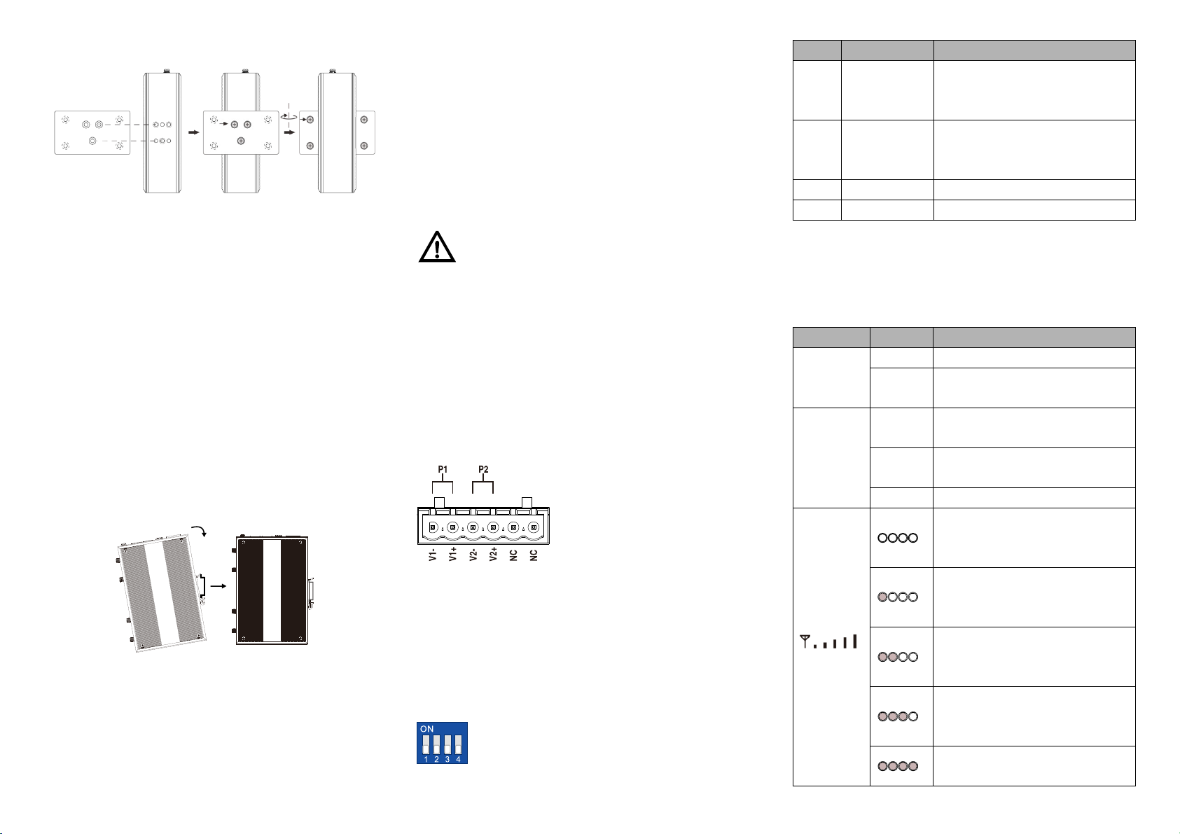
【Power Supply Connection】
DC power supply
The device provides 6-pin 5.08mm
pitch power supply input terminal
blocks, among which power supply
occupies the left 4 pins (the right 2
pins are reserved) Supports P1 and
P2 two independent DC power
supply systems, when one of the power supplies fails, it could
switch to another one immediately to ensure the device power
supply is not interrupted. Power supply supports non-polarity
and anti-reverse connection. Voltage range: 12~48VDC.
48VDC POE power supply input
The WAN port of this device supports POE power receiving.
【DIP Switch Settings】
The device provides 4 pins DIP switch for function
setting, in which “ON” is the enabled end. DIP
switches definition as follows:
DIP
Definition
operation
1 Restore
factory
defaults
Set the switch to ON and power
on the device again, then set it
back after one minute.
2 Reboot The device will restart
immediately after setting the DIP
to ON
3
Reserved
-
4
Reserved
-
【Checking LED Indicator】
The device provides LED indicators to monitor the device
working status with a comprehensive simplified
troubleshooting; the function of each LED is described in the
table as below:
LED
Indicate
Description
2.4G/5G
ON
WIFI is running normally
OFF
WIFI is running abnormally or
closed
RUN
ON The device is powered on or the
device is abnormal.
OFF The device is powered off or the
device is abnormal.
Blinking
The device is running normally
All indicators are off, which
means the WLAN signal at the
opposite end is weak or no signal
Only
one indicator is on, which
means the WLAN signal at the
opposite end is weak
Two indicators are on, which
means the WLAN signal at the
opposite end is normal
Three indicators are on, which
means the WLAN signal at the
opposite end is relatively strong
All indicators are on, which
means the WLAN signal at the
LED
Indicate
Description
opposite end is strong
ALM
ON
Restore factory settings alarm
OFF
No restore factory settings alarm
P1/P2
ON PWR is connected and running
normally
OFF
PWR is disconnected and
running abnormally
WAN/LAN
ON Copper port has established an
active network connection.
Blinking
Copper port is in a network
activity state.
OFF Copper port has not established
an active network connection.
POE
ON POE ports receive power supply
normally
OFF
POE is disabled or disconnected
【Logging in to WEB Interface】
This device supports WEB management and configuration.
Computer can access the device via LAN. The way of logging
in to device’s configuration interface via IE browser is shown
as below:
Step 1 Configure the IP addresses of computer and the
device to the same network segment, and the
network between them can be mutually accessed
Step 2 Enter device’s IP address in the address bar of the
computer browser.
Step 3 Enter device’s user name and password in the
login window as shown below.
Step 4 Click “Login” button to login to the WEB interface of
the device.
Note:
The default IP address of the device is “192.168.1.254”.
The default user name and password of the device is
“admin”.
If the username or password is lost, user can restore it to
factory settings via device DIP switch or management
software; all modified configurations will be cleared
after restoring to factory settings, so please backup
configuration file in advance.
Please refer to user manual for specific configuration
method of logging in to WEB interface and other
configurations about network management function.
【Specification】
Standard
Standard IEEE802.3, IEEE802.3u,
IEEE802.3ab, IEEE802.11a/b/g/n,
IEEE802.11i, IEEE802.11r,
IEEE802.11ac
Panel
Copper port 1 10/100/1000Base-
T(X) LAN
port, RJ45 port
1 10/100/1000Base-T(X) WAN
port,RJ45 port, supports PoE
48VDC power supply input
Antenna interface 
2 2.4G WIFI antenna
interfaces, RP-SMA-K type
(Female)
2 5G WIFI antenna interfaces,
RP-SMA-K type (Female)
Indicator
2.4G WLAN indicator, 5G WLAN
indicator, running indicator, power
supply indicator, alarm indicator,
WAN port connection indicator, LAN
port connection indicator, WLAN
bridging quality indicator, PoE
indicator
WIFI Transmission
Rate
802.11n
6.5~300Mbps
802.11b
11/5.5/2/1Mbps
802.11g/a
54/48/36/24/18/12/9/6Mbps
802.11ac
65Mbps~867Mbps
WIFI RF
2.4G channel
2.401GHz~2.483GHz
5G channel 5.170GHz~5.330GHz,
5.490GHz~5.650GHz,
5.735GHz~5.835GHz
RF power output
23dBm
Modulation scheme DBPSK, DQPSK, CCK, OFDM,
16-QAM, 64-QAM
WIFI Receiving
Sensitivity
802.11n_HT40
-82dBm@MCS0, -64dBm@MCS7
802.11n_HT20
-85dBm@MCS0, -67dBm@MCS7
802.11g/a -91dBm@6Mbps,
-72dBm@54Mbps
802.11b -93dBm@1Mbps,
-87dBm@11Mbps
802.11ac
-84dBm@MCS0, -59dBm@MCS9
WIFI Transmission
Power
802.11n_HT40
23dBm@MCS0, 20dBm@MCS7
802.11n_HT20
23dBm@MCS0, 20dBm@MCS7
802.11g/a
23dBm@6Mbps, 20dBm@54Mbps
802.11b
23dBm@1Mbps, 20dBm@11Mbps
802.11ac
23dBm@MCS0, 20dBm@MCS9
Power Supply
Input power supply Dual
power supply
redundancy, voltage range:
12 ~
48VDC, support
non-polarity, anti-reverse
connection, built-in overcurrent
2.0 protection

48VDC POE power supply
Access terminal
block
6-pin 5.08mm pitch terminal blocks
Power
Consumption
No-load
3.12W@24VDC
Full-load
9.87W@24VDC
Working
environment
Working
temperature
-40~75℃
Storage
temperature
-40~85℃
Working humidity
5%
~
95% (no condensation)

Other 3One data Wireless Access Point manuals

3One data IAP3600S-225-2GT-PDP12 48 User manual

3One data

3One data IAP3600S-225-2GT-PDP12 48 User manual

3One data IAP2600S Series User manual

3One data

3One data IAP2600S Series User manual

3One data IAP2600 Series User manual

3One data

3One data IAP2600 Series User manual

Popular Wireless Access Point manuals by other brands

Cisco Linksys WAP54G LA user guide

Cisco

Cisco Linksys WAP54G LA user guide

Cisco Aironet 521 quick start guide

Cisco

Cisco Aironet 521 quick start guide

Baicells Nova442i installation guide

Baicells

Baicells Nova442i installation guide

CommScope RUCKUS T350se Quick setup guide

CommScope

CommScope RUCKUS T350se Quick setup guide

Watchguard AP125 Hardware guide

Watchguard

Watchguard AP125 Hardware guide

SonicWALL SonicWave 432o Getting started guide

SonicWALL

SonicWALL SonicWave 432o Getting started guide

Zcom AC-1028 quick start guide

Zcom

Zcom AC-1028 quick start guide

4gon ENH202 user manual

4gon

4gon ENH202 user manual

Tranzeo EX2 user guide

Tranzeo

Tranzeo EX2 user guide

Cambium Networks cnPilot e501S Quick start guides

Cambium Networks

Cambium Networks cnPilot e501S Quick start guides

New H3C Technologies WA5630X installation guide

New H3C Technologies

New H3C Technologies WA5630X installation guide

ZyXEL Communications Wireless Access Point ZyAIR B-500 Quick installation guide

ZyXEL Communications

ZyXEL Communications Wireless Access Point ZyAIR B-500 Quick installation guide

D-Link UNIFIED WIRED & WIRELESS ACCESS SYSTEM... Deployment guide

D-Link

D-Link UNIFIED WIRED & WIRELESS ACCESS SYSTEM... Deployment guide

Harmonic MediaGrid ContentBridge 4000 installation guide

Harmonic

Harmonic MediaGrid ContentBridge 4000 installation guide

4IPNET OWL800 user manual

4IPNET

4IPNET OWL800 user manual

Edimax EW-7205AP user manual

Edimax

Edimax EW-7205AP user manual

Luminate LEAP-10 Hardware installation guide

Luminate

Luminate LEAP-10 Hardware installation guide

ZyXEL Communications NWA-3550 user guide

ZyXEL Communications

ZyXEL Communications NWA-3550 user guide

manuals.online logo
manuals.online logoBrands
  • About & Mission
  • Contact us
  • Privacy Policy
  • Terms and Conditions

Copyright 2025 Manuals.Online. All Rights Reserved.