3Z TELECOM Antenna W.A.S.P. User manual

Antenna W.A.S.P.
User’s Guide

2
REGULATORY SPECIFICATIONS 4
FCC PART 15 4
INDUSTRY CANADA NOTIFICATIONS 4
CE MARK CONFORMITY 5
RADIO FREQUENCY NOTIFICATIONS 7
FCC NOTIFICATIONS 7
LIST OF APPROVED ANTENNAS 8
ANTENNA WASP SYSTEM OVERVIEW 9
ANTENNA WASP SENSORS 9
DATA COLLECTORS 9
DATA COLLECTOR MANAGER 9
WASP TELEMETRY AND SENSOR MEASUREMENTS 10
3-D ORIENTATION (AZIMUTH,TILT,AND ROLL) 10
TEMPERATURE 10
BATTERY LEVEL 11
WIRELESS SIGNAL STRENGTH 11
ANTENNA WASP INSTALLATION GUIDE 12
STEP 1-INSTALL THE DATA COLLECTOR MANAGER SOFTWARE 12
STEP 2-INSTALL THE DATA COLLECTOR 16
STEP 3-INSTALL THE DATA COLLECTOR ANTENNA 18
STEP 4-RUN THE DATA MANAGER SOFTWARE 19
STEP 5-CONNECT TO THE DATA COLLECTOR 20
STEP 6-UPDATE SYSTEM TIME 21
STEP 7-APPLY POWER TO THE ANTENNA WASP SENSORS 22
STEP 8-CONFIGURE THE DATA COLLECTOR WITH ANTENNA WASP SENSORS 25
STEP 9-WAIT FOR ANTENNA WASP SENSORS TO CONNECT 30
STEP 10 –INSTALL ANTENNA WASPS ON THE ANTENNAS 31
STEP 11 -COMMISSION EACH ANTENNA WASP SENSOR 33
DATA COLLECTOR MANAGER SOFTWARE GUIDE 35
RUNNING THE DATA COLLECTOR MANAGER 35
CONNECTING TO A DATA COLLECTOR 36

3
SUMMARY VIEW 38
GENERAL SETTINGS TAB 39
SITE NAME SETTING 40
LOCATION SETTING 40
ALARM SETTINGS 40
ETHERNET SETTINGS TAB 41
SNMP SETTINGS TAB 42
ANTENNA WASP STATUS TAB 43
3D VIEW 44
ANTENNA WASP SETTINGS 46
ANTENNA WASP IDENTIFICATION 46
TARGET ORIENTATION 46
DOWNLOADING ANTENNA WASP DATA 47
3D PLAYBACK VIEW 49
GRAPH VIEW 50
TABLE VIEW 52
EXPORTING ANTENNA WASP DATA 52
TEMPERATURE GRAPH 53
TEMPERATURE TABLE 54
SYSTEM HISTORY 55
SYSTEM STATUS 57
PREFERENCES 58
AUTOMATIC REFRESH SETTING 58
TEMPERATURE UNITS 58
TECHNICAL SUPPORT CONTACTS 59

4
Regulatory Specifications
FCC Part 15
This equipment has been tested and found to comply with the limits for a Class A digital
device, pursuant to part 15 of the FCC Rules. These limits are designed to provide
reasonable protection against harmful interference when the equipment is operated in a
commercial environment. This equipment generates, uses, and can radiate radio
frequency energy and, if not installed and used in accordance with the instruction
manual, may cause harmful interference to radio communications. Operation of this
equipment in a residential area is likely to cause harmful interference in which case the
user will be required to correct the interference at his own expense.
Industry Canada Notifications
This device complies with Industry Canada’s license-exempt RSSs. Operation is subject
to the following two conditions:
(1) This device may not cause interference; and
(2) This device must accept any interference, including interference that may
cause undesired operation of the device.
Le présent appareil est conforme aux CNR d’Industrie Canada applicables aux
appareils radio exempts de licence. L’exploitation est autorisée aux deux conditions
suivantes:
(1) l’appareil ne doit pas produire de brouillage;
(2) l’utilisateur de l’appareil doit accepter tout brouillage radioélectrique subi,
même si le brouillage est susceptible d’en compromettre le fonctionnement.
5
CE Mark Conformity

6
3Z Telecom, Inc. declares that the WASP Sensor and Data Collector products conform
to their respective specifications, following the provisions of the European R&TTE
directive 1999/5/EC:
3Z Telecom, Inc. déclare que les produits est conforme aux conditions essentielles et
aux dispositions relatives à la directive 1999/5/EC:
• EN 301 489-1 General EMC requirements for Radio equipment.
• EN 300 328 Technical requirements for Radio equipment.
CAUTION—The products are intended to be used in all EU and EFTA countries.
Outdoor use may be restricted to certain frequencies and/or may require a license for
operation. Contact local authority for procedure to follow.
Note: ESD precautions should be used when attaching or removing the antenna from
the Data Collector.
Note: Combinations of power levels and antennas resulting in a radiated power level of
above 100 mW equivalent isotropic radiated power (EIRP) are considered as not
compliant with the above mentioned directive and are not allowed for use within the
European community and countries that have adopted the European R&TTEdirective
1999/5/EC. For more details on legal combinations of power levels and antennas,
contact 3Z Telecom, Inc.
Protect the Data Collector from water. Do not use if Data Collector gets wet.
Avoid using these products during an electrical storm. There may be a remote risk of
electric shock from lightning.

7
Radio Frequency Notifications
FCC Notifications
RF Radiation: The Product is an intentional radiator of Radio Frequency (RF) energy.
In order to limit RF exposure to personnel in the immediate area, the Product should be
located and installed such that a separation of at least 20 centimeters is maintained
between the Product’s antenna and personnel in the vicinity of the device. The antenna
used for this transmitter must not be co-located or operated in conjunction with any
other antenna or transmitter.
Modification warning: Caution - changes or modifications to this equipment, not
expressly approved by 3Z Telecom, Inc. could void the user’s authority to operate the
equipment.

8
List of Approved Antennas
To reduce potential radio interference to other users, the antenna type and its gain
should be so chosen that the equivalent isotropically radiated power (E.I.R.P.) is not
more than that required for successful communication. This device has been designed
to operate with the antennas listed below. Antennas not included in this list are strictly
prohibited for use with this device. The required antenna impedance is 50 ohms.
Please note that the WASP Sensor is designed to only operate with an internal, non-
user-replaceable antenna. Therefore the list below is applicable only to the Data
Collector.
List of Approved Antennas for Data Collector
Manufacturer
Model
Type
Connector
Gain
(dBi)
Note
1
Telestone
STQJ-2400-5
Omnidirectional
SMA plug
reverse polarity
via provided
antenna cable
5
2
Galtronics
02008073-
05831
Omnidirectional
SMA plug
reverse polarity
via provided
antenna cable
2.5
Assembled within
same enclosure
as Antenna #3
3
Galtronics
02008073-
05831
Directional
SMA plug
reverse polarity
via provided
antenna cable
8
Assembled within
same enclosure
as Antenna #2

9
Antenna WASP System Overview
Antenna WASP Sensors
The antenna WASP sensors are designed with a highly sensitive digital compass and
inclinometer to precisely measure the orientation of cellular antennas and to wirelessly
relay the information back to the Data Collector.
Data Collectors
The Data Collector is an embedded computer installed at each installation site that
receives and records antenna WASP sensor information. The Data Collector is also
responsible for:
Monitoring the sensor data and raising alarms when out-of-range measurements
are detected.
Generate SNMP traps (optional)
Data Collector Manager
The Data Collector Manager is a Windows application which is responsible for:
Configuring the settings in one or more Data Managers.
Downloading and viewing antenna WASP sensor data from Data Managers.
10
WASP Telemetry and Sensor Measurements
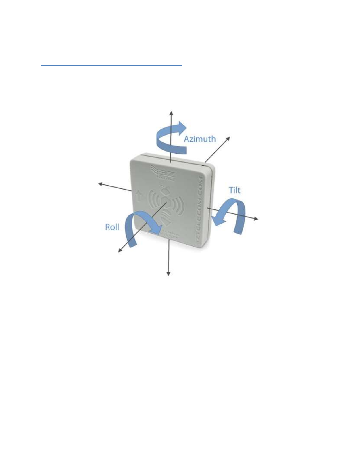
3-D Orientation (Azimuth, Tilt, and Roll)
The antenna WASP sensor contains a highly sensitive magnetometer and inclinometer
which can detect very slight changes in orientation. The antenna WASP sensor
measures orientation on three different axes as illustrated below.
Azimuth –is an angular measure relative to the Earth’s magnetic field and is
specified in degrees offset from magnetic north. This value can range from 0
degrees (north) to 359 degrees.
Roll –is a measure of the sensor’s deviation from level with respect to the
horizon. This parameter can range from -180 degrees to 180 degrees.
Tilt –is a measure of the sensor’s deviation from vertical (zero degrees). This
parameter can range from -180 degrees to 180 degrees.
Temperature
The antenna WASP sensors are also equipped with a temperature sensor which will
measure and report the ambient temperature at the sensor location in degrees Celsius
or Fahrenheit.

11
Battery Level
Each antenna WASP sensor monitors and reports the battery level to give the user
plenty of notice before the battery needs to be replaced.
Wireless Signal Strength
In any wireless network the signal strength of the received signal is a key measure of
the reliability of the wireless link. The antenna WASP makes Received Signal Strength
Indicator (RSSI) measurements (in units of dBm) at both ends of each wireless link and
reports the information to the Data Collector. Very low RSSI measurements can indicate
that a sensor is at the limit of the wireless range or that something has moved into the
transmission path and is blocking the signal. This signal strength information can be
configured to generate alarm conditions and may be used by technicians to
troubleshoot the network.
When the antenna WASP sensor transmits sensor information to the Data Collector, the
receiver within the Data Collector makes a measurement of the RSSI, as illustrated
below.
Occasionally the Data Collector will send commands or upload information to the WASP
sensor, in which case the WASP sensor measures the received signal strength and
relays the measurement back to the Data Collector the next time it transmits sensor
information. This situation is illustrated below.
12
NOTE: The Data Collector only occasionally sends commands to the WASP sensors,
so this second measurement may not always be available (which is normal).
Antenna WASP Installation Guide
Step 1 - Install the Data Collector Manager Software
In order to configure the Antenna WASP sensors and Data Collector you will need to
install the Data Collector Manager Software on a PC which has at least one USB
connection and is running Windows 7, Windows 8.1 or Windows 10.
To install the software on your Windows system, please do the following:
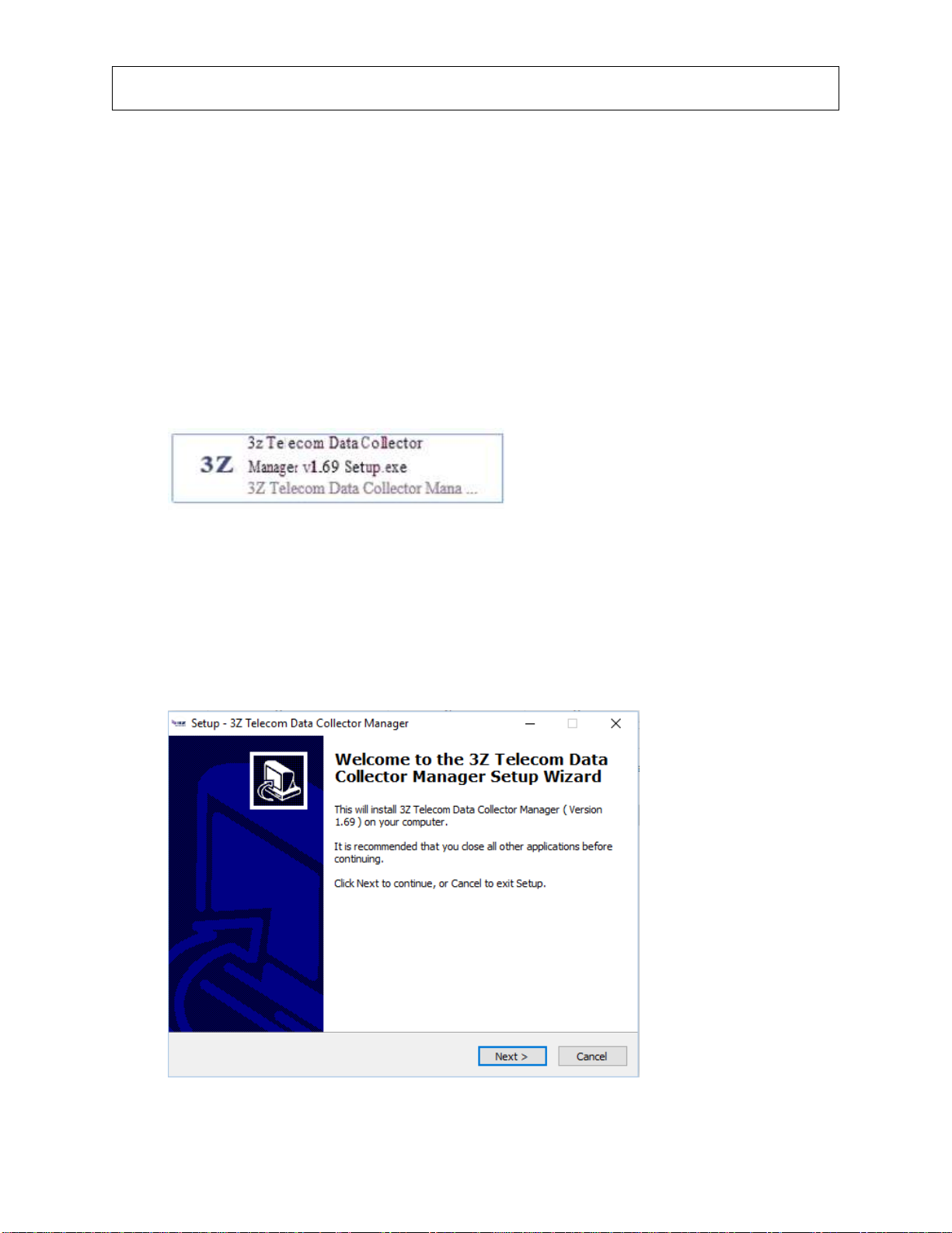
1. Open Windows Explorer and locate the Data Collector Manager Installer file
as distributed by 3z Telecom. It should look similar to the following:
2. Double click the installer file to start the installation process. You may be
required to enter Administrator credentials for the computer. If you do not have
the required credentials, you will need to contact your network or system
administrator.
3. When the installer starts, you will see a window as shown below:
4. Click ‘Next’to continue.

13
5. Next, you will see a screen which allows you to choose the installation location
for the software as shown below. It is recommended to choose the default
installation location.
6. Click ‘Next’to continue.
7. Next, you will be asked to select the Start Menu folder as shown below .It is
recommended to choose the default name.
8. Click ‘Next’ to continue.
14
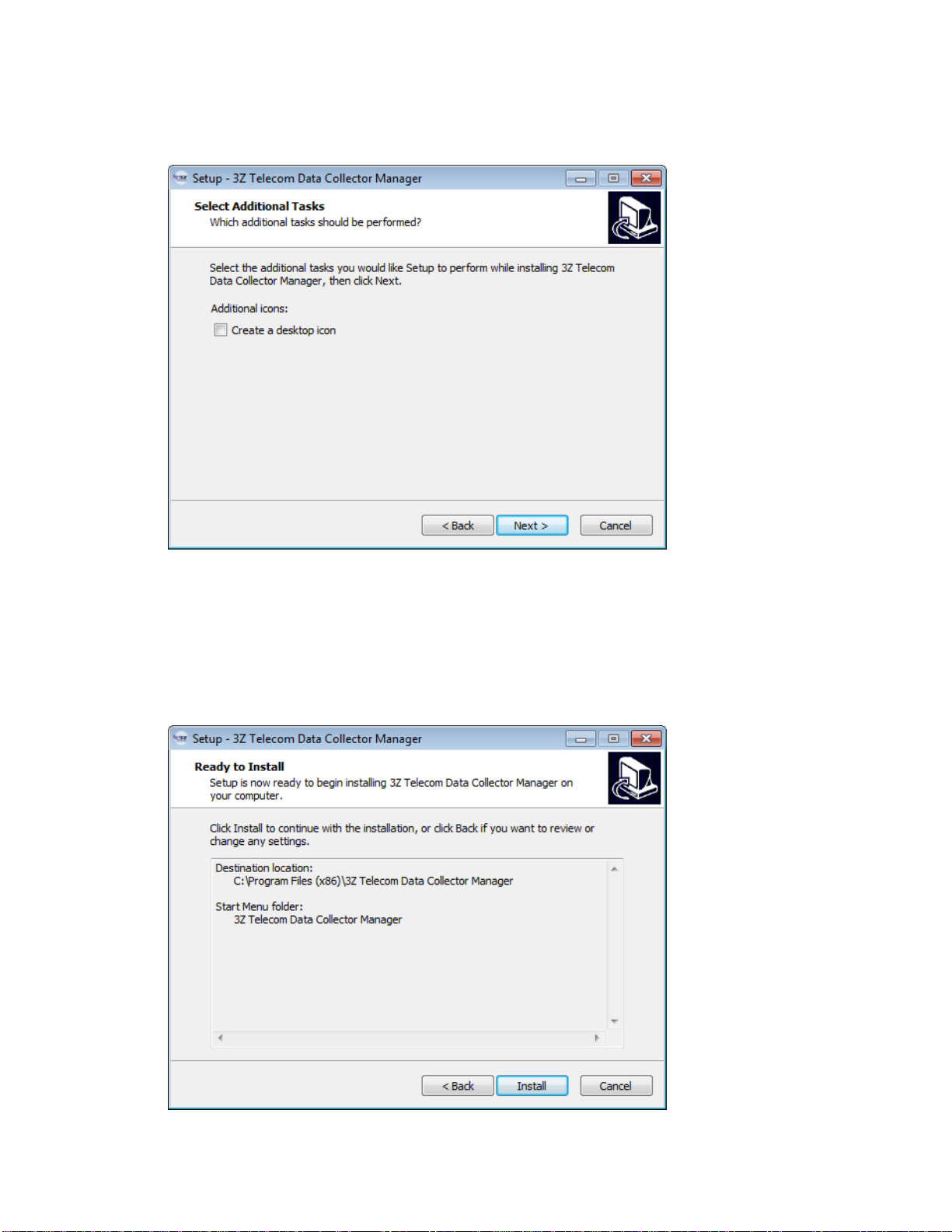
9. You will then be asked if you would like to optionally create a desktop icon for the
Data Collector software as shown below.
10.Click ‘Next’ to continue.
11.Finally, you will be prompted to confirm the installation details with a window
similar to the one shown below. Confirm that the information is correct and click
‘Next’.
15
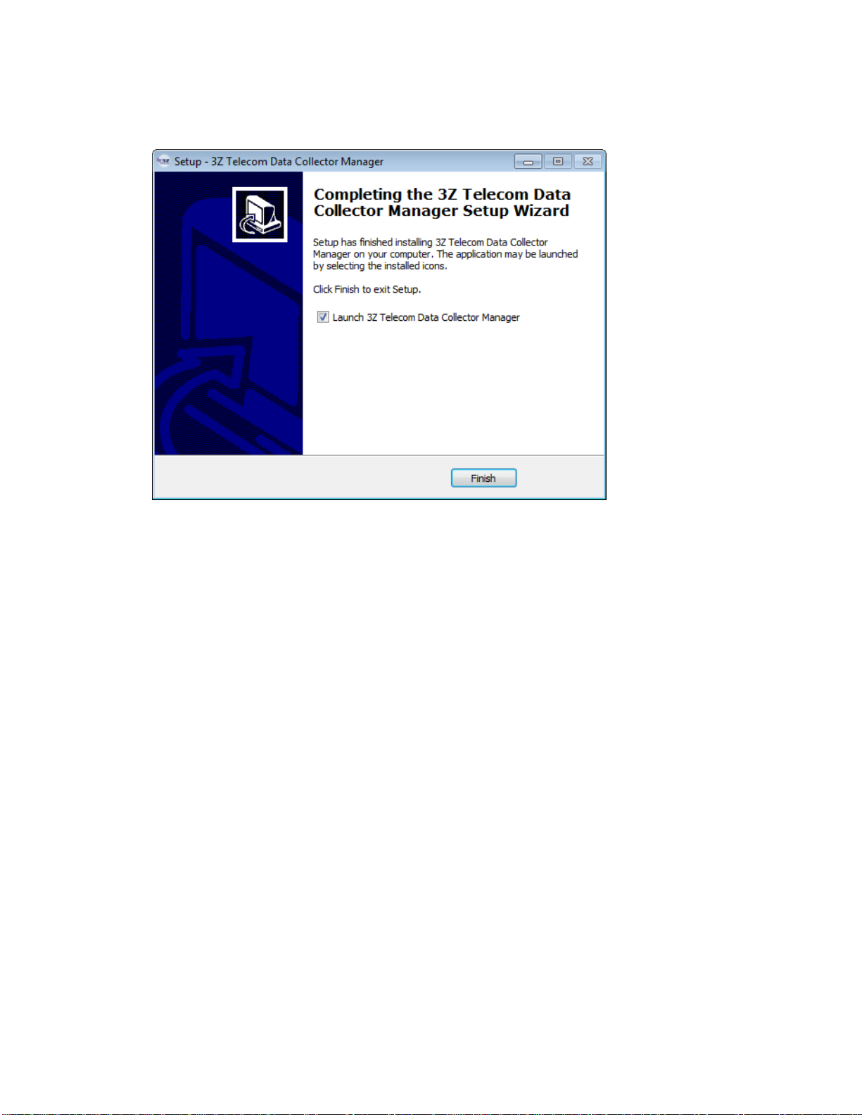
12.The installer will then install the Data Collector Manager software onto your
Windows computer. When it is finished, you will be prompted with a completion
screen as shown below.
13.Click ‘Finish’ to complete the installation.
16
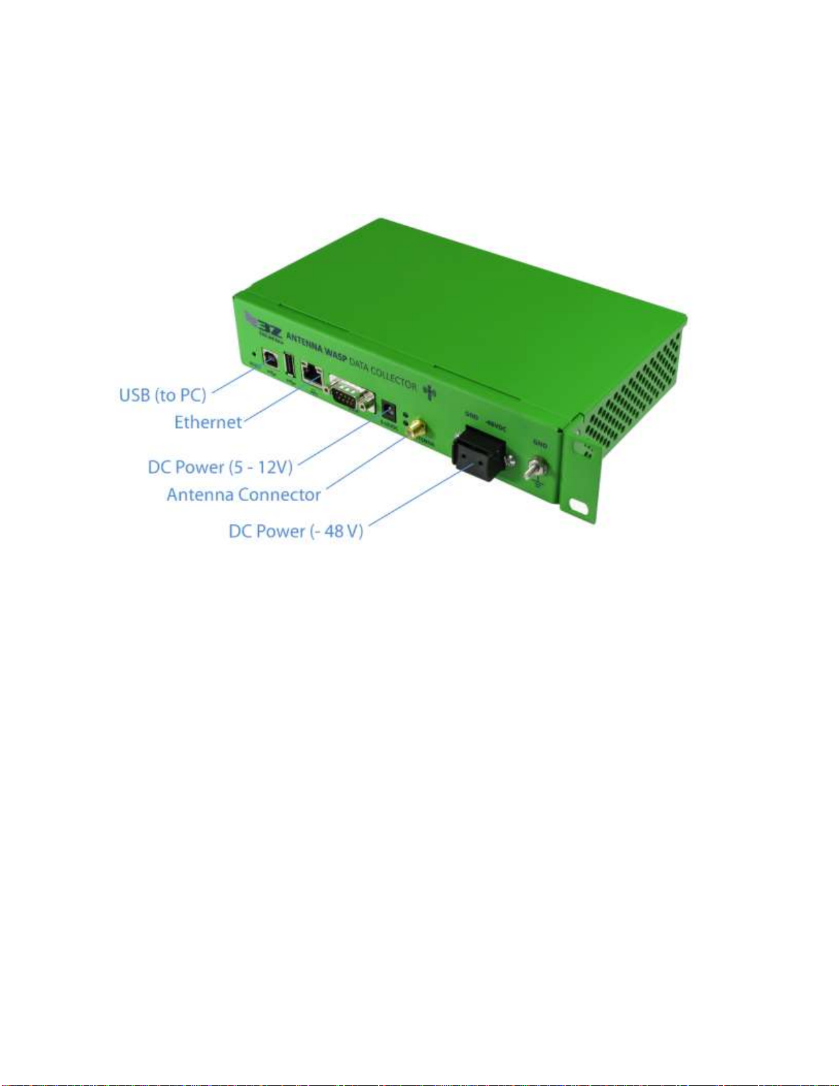
Step 2 - Install the Data Collector
Installation of Data Collector is intended to be performed by professional personnel.
The Data Collector must be installed in a cool dry location on site, and should be easily
accessible. Once the Data Collector is firmly fixed to a solid surface, you may make the
necessary cable connections as described and illustrated below.
1. Attach the antenna to the antenna connector illustrated above. Use an
appropriate torque wrench set to 8 inch-pounds to ensure the connector is firmly
attached (but do not over tighten).
2. Connect the Ethernet to a LAN device (router). For remote connectivity,
connect a standard CAT5 with RJ45 connector from the Ethernet port to router.
Make 2 loops of the Ethernet cable around ferrite core (Fair-Rite 0446167251(1)),
and secure the cable loops by clamping shut the ferrite core assembly.
3. Connect DC Power (-48V) port to power source at the base of the tower.
Once you have connected DC power to the Data Collector the green power LED
next to the Antenna Connector will turn on. This indicates that the system has
power and the system software is loading.
4. Connect a USB cable from the PC to the Data Collector using the device USB
port as shown above.
Attention: The two USB Ports, 9-pin Serial Port, and Power Jack (5-12V) are only used
for system debug and configuration purposes. These ports are not to be connected to
any device during normal operation.

17
Attention: The Data Collector’s Ethernet Port is designed to only connect to a
commercially available network router. The Data Collector is not designed to be a
peripheral device to a Class B Personal Computer (PC). As such, the Ethernet Port shall
not be connected to a Class B PC in any operating configuration.
Attention: The sole power source of the Data Collector is -48VDC supplied by a power
source at the base of the tower. The Data Collector does not require connections at the
two USB Ports nor the Power Jack (5-12V) to operate.
Note on Ferrite Cores: The Fair-Rite 0446167251 clamp-on ferrite core is necessary to
filter electromagnetic noise on the Ethernet cable. It must be installed to meet EMC
requirements. It must be fastened onto the Ethernet cable as described in part 2 above,
as close to the Data Collector as possible.
(1) Fair-Rite 0446167251 not included.
18
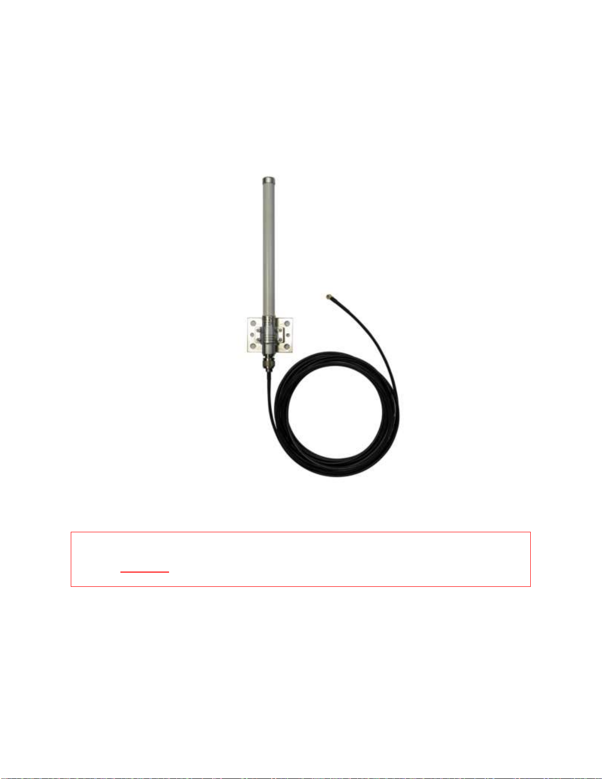
Step 3 - Install the Data Collector Antenna
Installation of the Data Collector antenna is intended to be performed by professional
personnel.
The Data Collector ships with a 2.4 GHz omnidirectional antenna and N-to-RPSMA
coaxial cable (as shown below). The antenna must be installed with direct line of sight
to the Antenna WASP sensors installed on the antennas.
WARNING: Always be aware of power lines and ensure this antenna is installed
at least 4 meters away from any high voltage lines.
Also note:
Ensure the antenna is fixed firmly to a rigid surface and will not be moved by
wind or adverse weather conditions.
Ensure the attached cable will reach the Data Collector installation site.

19
Step 4 - Run the Data Manager Software
Run the Data Collector Manager software that was installed in Step 1 by clicking on the
‘3z Telecom Data Collector Manager’ application. A login prompt will appear as shown
below.
Enter your username and password and click ‘Login’. When you have successfully
logged in to the software, the manager window will appear as shown below.

20
After a few moments, the manager software will detect the Data Collector connected on
USB and the Data Collector will appear in the left pane as shown below.
Step 5 - Connect to the Data Collector
To connect to a Data Collector you may:
Double click the Data Collector’s name link in the left pane, or
Select “Data Collector -> Connect” from the File menu.
If the Data Collector has not previously been configured, then the screen will look very
similar to the image below.
Once a connection to the Data Collector is established proceed to Step 6 - Update
System Time.
Table of contents
Other 3Z TELECOM Antenna manuals

Popular Antenna manuals by other brands


TERK Technologies
TERK Technologies FM Edge user guide

AC Antennas
AC Antennas KUM400 Series installation guide

KMW Communications
KMW Communications ET-X-TU-42-15-37-18-iR-RA installation guide

Amphenol Procom
Amphenol Procom GF 404/ Series quick start guide

MFJ
MFJ 2013 instruction manual

Wilson Electronics
Wilson Electronics 301133 installation guide