4-noks ZR-HM.D-RC Quick guide

Installation and instruction manual
4-noks
Energy Meter 1~ RC
IT EN FR DE


3
Summary
Manuale installazione e istruzioni d’uso ............................................................ 6
1. Descrizione generale ....................................................................................................6
Contenuto della confezione........................................................................................................................................................6
Requisiti minimi.........................................................................................................................................................................6
2. Avvertenze di sicurezza................................................................................................6
Attenzione .................................................................................................................................................................................6
3. Installazione..................................................................................................................6
Prima dell’installazione..............................................................................................................................................................6
Fissaggio...................................................................................................................................................................................7
Collegamenti .............................................................................................................................................................................7
Prima accensione......................................................................................................................................................................7
Verifica installazione..................................................................................................................................................................7
Funzionamento..........................................................................................................................................................................7
4. Comportamento LED (tab. 1) .......................................................................................7
5. Funzione pulsante (tab. 2) ............................................................................................8
6. Risoluzione problemi ....................................................................................................8
7. Specifiche tecniche ......................................................................................................8
8. Conformità....................................................................................................................9
9. Sicurezza e smaltimento ..............................................................................................9
10. Schemi installazione.....................................................................................................9
Energy Meter per controllo consumi carico (fig. 3) .....................................................................................................................9
Energy Meter collegato al contatore di scambio (fig. 4)............................................................................................................10
Energy Meter collegato al contatore di produzione (fig. 5)........................................................................................................11
Installation and instruction manual .................................................................. 12
1. General description ....................................................................................................12
Contents of the pack................................................................................................................................................................12
Minimum requirements ...........................................................................................................................................................12
2. Safety warnings..........................................................................................................12
Caution....................................................................................................................................................................................12
3. Installation .................................................................................................................12
Prior to installation...................................................................................................................................................................12
Fixing ......................................................................................................................................................................................13
Connections ............................................................................................................................................................................13
First power-up.........................................................................................................................................................................13
Check installation....................................................................................................................................................................13
Operation ................................................................................................................................................................................13
4. Response of Leds (table 1).........................................................................................13
5. Operation of button (table 2) ......................................................................................14
6. Troubleshooting..........................................................................................................14
7. Technical specifications .............................................................................................14
8. Conformity..................................................................................................................15
9. Safety and disposal....................................................................................................15
10. Installation diagrams ..................................................................................................15
Energy Meter for monitoring power drawn by load (fig. 3) .......................................................................................................15
Energy Meter connected to transfer meter (fig. 4) ....................................................................................................................16
Energy Meter connected to production meter (fig. 5)................................................................................................................17

4
Manuel d’installation et mode d’emploi ........................................................... 18
1. Description générale ..................................................................................................18
Contenu de l’emballage...........................................................................................................................................................18
Configurations minimales ........................................................................................................................................................18
2. Consignes de sécurité................................................................................................18
Attention..................................................................................................................................................................................18
3. Installation ..................................................................................................................19
Avant l’installation ...................................................................................................................................................................19
Fixation ...................................................................................................................................................................................19
Branchements.........................................................................................................................................................................19
Premier allumage ....................................................................................................................................................................19
Vérification de l’installation......................................................................................................................................................19
Fonctionnement.......................................................................................................................................................................19
12. Comportement LED (tableau 1)..................................................................................19
13. Fonction touche (tableau 2)........................................................................................20
14. Résolution des problèmes..........................................................................................20
15. Spécifications techniques ..........................................................................................20
16. Conformité..................................................................................................................21
17. Sécurité et élimination................................................................................................21
18. Schémas d’installation ...............................................................................................21
Energy Meter pour le contrôle de la consommation de la charge (fig. 3)...................................................................................21
Energy Meter connecté au compteur d’énergie échangée (fig. 4) .............................................................................................22
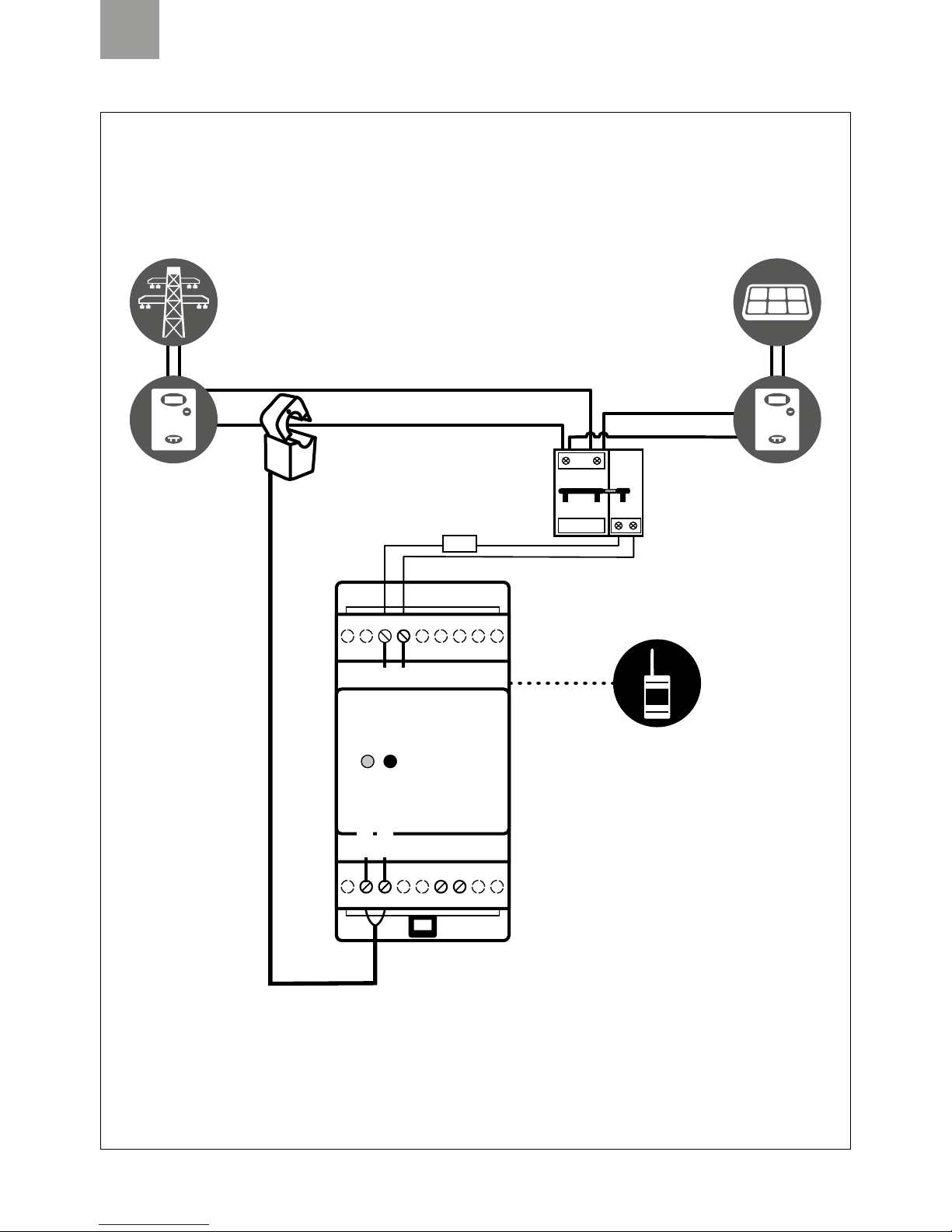
Energy Meter connecté au compteur de production (fig. 5) ......................................................................................................23
Installations- und Bedienungsanleitung........................................................... 24
1. Allgemeine Beschreibung...........................................................................................24
Verpackungsinhalt...................................................................................................................................................................24
Mindestsystemvoraussetzungen..............................................................................................................................................24
2. Sicherheitshinweise....................................................................................................24
Warnung..................................................................................................................................................................................24
3. Installation ..................................................................................................................24
Vor der Installation...................................................................................................................................................................24
Befestigung.............................................................................................................................................................................25
Anschlüsse..............................................................................................................................................................................25
Erstmalige Einschaltung ..........................................................................................................................................................25
Test der Installation .................................................................................................................................................................25
Betrieb ....................................................................................................................................................................................25
12. LED-Verhalten (Tab. 1)................................................................................................25
13. Tastenfunktion (Tab. 2) ...............................................................................................26
14. Problembehebung......................................................................................................26
15. Technische Daten .......................................................................................................26
16. Konformität.................................................................................................................27
17. Sicherheit und Entsorgung.........................................................................................27
18. Installationspläne........................................................................................................27
Energy Meter für die Verbrauchsüberwachung der Last (Abb. 3) ..............................................................................................27
Energy Meter mit Anschluss an den Zweirichtungszähler (Abb. 4)............................................................................................28
Energy Meter mit Anschluss an den Erzeugungszähler (Abb. 5)................................................................................................29
Note / Notes / Notes / Anmerkungen ............................................................... 30

5
Codice / Code Nome / Name
ZR-HM.D-RC Energy Meter 1~ RC
IT / Leggere e conservare queste istruzioni
EN / Read and keep these instructions
FR / Lisez et conservez ce manuel
DE / Diese Anleitung lesen und aufbewahren
ZR-HM.D-RC

IT
6
Manuale installazione e istruzioni d’uso
1. Descrizione generale
Energy Meter 1~ RC è un misuratore di potenza con trasmissione dati di tipo wireless per i sistemi Elios4you Smart. Può sostituire uno dei
misuratori di energia (TA) collegati a Elios4you Smart oppure può essere utilizzato per monitorare la potenza di un carico (es. elettrodomestico
o sistema di accumulo). In caso si utilizzi Energy Meter 1~ RC per la remotazione di un TA dell’Elios4you Smart, non vi saranno sostanziali
differenze nelle informazioni visualizzate all’interno dell’App. Nel caso si utilizzi il dispositivo per monitorare un carico, all’interno dell’App
verrà visualizzata la potenza istantaneamente consumata dal carico.
Contenuto della confezione
91 Energy Meter 1~ RC
91 trasformatore amperometrico (TA)
Requisiti minimi
9Elios4you Smart
9App gratuita “Elios4you” aggiornata all’ultima versione disponibile
2. Avvertenze di sicurezza
Tutti i collegamenti hardware devono essere effettuati da personale qualificato e consapevole dei rischi di un’installazione tenendo conto dei
minimi standard di sicurezza ed in assenza di tensione. L’utente si assume ogni responsabilità e rischio in relazione alle fasi di installazione,
configurazione e utilizzo dei prodotti per il raggiungimento dei risultati previsti dal singolo prodotto. La responsabilità di Astrel Group in relazio-
ne ai propri prodotti è regolata dalle Condizioni generali di vendita Astrel Group (consultabili sul sito www.astrelgroup.com).
Non smontare, aprire o provare a riparare il prodotto. L’apertura di un componente sigillato annulla la garanzia.
Attenzione
Energy Meter 1~ RC esegue letture di corrente alternata (AC), non può essere utilizzato per il monitoraggio di sistemi d’accumulo nel lato
di corrente continua (DC). È possibile associare al massimo 3 Energy Meter 1~ RC ad ogni Elios4you Smart, uno per ogni modalità di lettura
prevista (Produzione / Scambio / Altro).
3. Installazione
Prima dell’installazione
1) Verificare che la distanza a cui viene installato Energy Meter 1~ RC (di seguito Energy Meter RC) sia compatibile con le specifiche
di portata radio indicate nelle specifiche tecniche. Attenzione: la portata radio tra i due dispositivi garantisce tipicamente il
superamento di un solaio o parete portante. In caso di mancata copertura radio utilizzare un ripetitore.
45 mm
53,5 mm
48,3 mm
62 mm
110 mm
19 18 17 16 15 14 13 12 11
123456789
L N
TA+ (rosso)
TA- (nero)
LED
Pulsante
Fig. 1 Fig. 2

IT
7
2) Verificare che la App “Elios4you” installata sul proprio tablet / smartphone sia in comunicazione con il dispositivo Elios4you Smart
3) Scollegare il TA cablato di Elios4you Smart che verrà sostituito dall’Energy Meter RC. Tale operazione è necessaria solo nel caso in cui
il dispositivo venga utilizzato in sostituzione ad un TA
Fissaggio
4) Fissare Energy Meter RC alla barra DIN
Collegamenti
5) Togliere l’alimentazione elettrica in ingresso nel luogo di installazione
6) Effettuare i collegamenti elettrici come indicato nello Schema di installazione (fig. 3).
7) Attenzione: il TA deve essere pinzato esclusivamente sulla fase (L) con l’orientamento indicato nello schema. Il TA è in grado di
distinguere il verso della corrente, la sua inversione può generare errori di lettura.
Prima accensione
8) Alimentare l’Energy Meter RC
9) Verificare che, all’accensione, il LED di segnalazione (fig. 2) lampeggi di colore rosso. Se il LED si accende in modo fisso (rosso o
verde), eseguire la procedura di disassociazione utilizzando il pulsante (vedi tab.2)
10) Avviare la App “Elios4you” Menu Smart RC “Aggiungi dispositivo Smart RC” “Avvia procedura” e selezionare la
tipologia di misura da assegnare a Energy Meter RC (Produzione/Scambio/Altro).
Per maggiori informazioni: www.4-noks.com/tutorial
11) Solo se Energy Meter RC viene utilizzato per misurare una potenza consumata da un carico: accedere alla sezione
“Preferenze” ed attivare la spunta su “Visualizza Smart Plug”
Verifica installazione
L’Energy Meter RC collegato è rappresentato dall’icona in corrispondenza delle icone “Rete” o “Produzione” nel caso in cui sia
installato in sostituzione di uno dei due TA. In funzione dell’intensità del segnale radio tra Energy Meter RC ed Elios4you Smart, l’icona
potrà essere
Se Energy Meter RC è utilizzato per misurare lo scambio con un carico, il dato rilevato sarà visibile con un’icona sulla schermata principale
dell’App “Elios4you”.
Verificare la correttezza della lettura di potenza:
9se utilizzato per la lettura della potenza prodotta dal fotovoltaico, confrontare la lettura con quella riportata dall’inverter
9se utilizzato per la lettura della potenza scambiata con la rete, verificare la correttezza del verso indicato della corrente e la sua
differenza da 0.
9se utilizzato per il controllo di consumo di carico, accendere quest’ultimo e verificare che la lettura della potenza da lui consumata
sia differente da 0.
Funzionamento
Accedendo alla schermata principale dell’App “Elios4you”, sarà possibile visualizzare la misura eseguita dal dispositivo Energy Meter RC.
Nota: in caso di assenza di segnale radio tra Energy Meter RC ed Elios4you Smart, si perderà solo il dato sulla produzione istantanea, mentre
il dato relativo all’energia (progressivo) viene mantenuto e sarà visibile non appena verrà ripristinato il collegamento radio.
4. Comportamento LED (tab. 1)
LED Stato Significato
Arancio Acceso fisso /
lampeggiante Reset dispositivo in corso
Rosso Lampeggiante Dispositivo non associato in rete
Rosso Fisso Dispositivo associato correttamente
Verde Fisso Dispositivo associato correttamente

IT
8
5. Funzione pulsante (tab. 2)
Funzione Comando Significato
Associazione
Pressione
breve (circa
1 s)
Attiva la funzione di associazione di Energy Meter RC ad Elios4you Smart
Disassocia-
zione
Pressione
prolungata
(circa 10 s)
Energy Meter RC non più associato a Elios4you Smart
Reset
Pressione
prolungata
(circa 25 s)
La funzione Reset ripristina il dispositivo ai parametri di fabbrica. Tutti i dati memorizzati vengono
eliminati
6. Risoluzione problemi
1) Non viene letta la potenza prodotta dall’impianto fotovoltaico
9Verificare il passaggio del solo cavo di fase all’interno del TA dell’Energy Meter RC
9Ruotare il verso del TA di 180 gradi
2) Non viene letta la potenza scambiata con la rete in modo corretto
9Verificare il passaggio del solo cavo di fase all’interno del TA dell’Energy Meter
9Ruotare il verso del TA di 180 gradi
3) Energy Meter RC misura una potenza consumata dal carico con segno negativo:
9Ruotare il verso del TA di 180 gradi
4) Durante la procedura di associazione dell’Energy Meter RC non viene rilevato alcun dispositivo
9Verificare che il LED del dispositivo sia di colore rosso lampeggiante
9Verificare la distanza tra Elios4you Smart ed Energy Meter, eventualmente avvicinare quest’ultimo o installare un ripetitore
7. Specifiche tecniche
Caratteristiche generali Misuratore di potenza monofase con trasmissione dati ZigBee
Alimentazione 90/250 Vac; 1 W; 50/60 Hz
Caratteristiche radio
• Frequenza: 2405 MHz ÷ 2480 MHz
• Compatibile IEEE 802.15.4
• Potenza trasmissione; +3 dBm ERP (2 mW)
• Antenna interna
• Portata radio 20 m indoor / 50 m outdoor. Nota: la distanza è indicativa e può variare in funzione
delle condizioni ambientali (dimensioni e materiale di muri /solai, etc.)
Misure • Potenza attiva bidirezionale [W]
• Energia bidirezionale [Wh]
Connessioni Morsetti a vite (passo 5,08 mm)
TA Ø 15 mm - 100/33 mA
Parametri ambientali • Condizioni di utilizzo: -10 ÷ +60°C; <80% U.R. n.c.
• Condizioni di stoccaggio: -20 ÷ +70°C; <80% U.R. n.c.
Grado di protezione IP20
Conformità Direttive Comunitarie 2006/95/EEC, 89/336/EEC, 99/5/EEC; ETSI-EN 300 328; ETSI EN301 489; EN
50371; EN60950-1; EN61000-6-2; EN6100
Dimensioni (L x H x P) 53,5 x 110 x 62 mm

IT
9
8. Conformità
Tutti i modelli sono conformi alle direttive 2014/30/UE (EMC), 2014/35/UE (LVD) e 2014/53/UE (RED). L’apparecchiatura (o il prodotto) deve
essere soggetto alla raccolta separata in conformità alle vigenti normative locali in materia di smaltimento. Con la presente Astrel Group
dichiara che questo prodotto è conforme ai requisiti essenziali ed alle disposizioni pertinenti stabilite dalla direttiva 2014/53/UE (RED).
La dichiarazione di conformità può essere consultata sul sito www.astrelgroup.com.
9. Sicurezza e smaltimento
Apparecchiatura elettrica ed elettronica oggetto di raccolta separata, in conformità alle vigenti normative locali in materia di smaltimento.
Astrel Group si riserva il diritto di modificare le caratteristiche dei prodotti senza preavviso.
10. Schemi installazione
Energy Meter per controllo consumi carico (fig. 3)
19 18 17 16 15 14 13 12 11
123456789
L N
TA+ (rosso)
TA- (nero)
L
N
L
N
Elios4you Smart
Contatore
di produzione
Contatore
di scambio
Magnetotermico e
differenziale generale
L
1A
N
Collegamento
wireless
Elettrodomestico
Energy Meter 1~ RC

IT
10
Energy Meter collegato al contatore di scambio (fig. 4)
19 18 17 16 15 14 13 12 11
123456789
L N
TA+ (rosso)
TA- (nero)
Elios4you Smart
L
N
L
N
TA scabio: punto verde
e direzione della freccia K L
verso il magnetotermico
e differenziale generale
Contatore
di produzione
Contatore
di scambio
Magnetotermico e
differenziale generale
L
1A
N
Collegamento
wireless
Energy Meter 1~ RC

IT
11
Energy Meter collegato al contatore di produzione (fig. 5)
19 18 17 16 15 14 13 12 11
123456789
L N
TA+ (rosso)
TA- (nero)
L
N
L
N
Elios4you Smart
Contatore
di produzione
TA produzione
Contatore
di scambio
Magnetotermico e
differenziale generale
L
1A
N
Collegamento
wireless
Energy Meter 1~ RC

EN
12
45 mm
53,5 mm
48,3 mm
62 mm
110 mm
19 18 17 16 15 14 13 12 11
123456789
L N
CT+ (red)
CT- (black)
LED
Button
Installation and instruction manual
1. General description
The Energy Meter 1~ RC is a wireless power metering device with data transmission for Elios4you Smart systems. It can replace one of the
Elios4you Smart measurement transformers (CT), or it can be used to monitor the power drawn by a load (e.g. household electrical appliance
or storage system). If the Energy Meter 1~ RC is used for remoting a CT of the Elios4you Smart, there will be no substantial differences in the
information displayed internally of the App. If the device is used for monitoring a load, the App will display the amount of power consumed
instantaneously by the load.
Contents of the pack
91 x Energy Meter 1~ RC
91 x current transformer (CT)
Minimum requirements
9Elios4you Smart
9Free “Elios4you” App updated to the latest version available
2. Safety warnings
All hardware connections must be made by a person who is suitably qualified and aware of the risks associated with installation, observing
the requisite standards of safety, and with the equipment isolated from the power supply. The user accepts all responsibilities and risks
connected with the steps of installing, configuring and using products to the end of obtaining the benefits and advantages they afford. The
liability of the Astrel Group in respect of its products is regulated by the Astrel Group General Conditions of Sale (published on the company’s
website www.astrelgroup.com).
Do not disassemble, open up or attempt to repair the product. Opening up a sealed component has the effect of invalidating the warranty.
Caution
The Energy Meter 1~ RC takes readings of alternating current (AC); it cannot be used to monitor storage systems on the direct current (DC)
side. Up to 3 Energy Meter 1~ RC devices can be paired with each Elios4you Smart, one for each reading mode envisaged (Production /
Transfer / Other).
3. Installation
Prior to installation
1) Check that the distance at which the Energy Meter 1~ RC (also ‘Energy Meter RC’ in this manual) is installed from the load will be
compatible with the radio range indicated in the technical specifications. Caution: the radio range between the two devices will
Fig. 1 Fig. 2

EN
13
typically guarantee transmission through a suspended floor slab or a load-bearing wall. If radio coverage proves to be unavailable,
use a repeater.
2) Check that the “Elios4you” App installed on the tablet / smartphone is communicating correctly with the Elios4you Smart device.
3) Disconnect the Elios4you Smart wired CT, which will be replaced by the Energy Meter RC. This operation is necessary only in the
event that the device is going to be used in place of a CT.
Fixing
4) Mount the Energy Meter RC to the DIN rail.
Connections
5) Shut off the electrical power supply to the installation site.
6) Make the electrical connections as indicated in the installation diagram (fig. 3).
7) Caution: The CT must be clamped only on the phase line (L), and positioned as shown in the diagram. Given that the CT is able to
distinguish the direction of the current, it can create reading errors if placed the wrong way round.
First power-up
8) Supply power to the Energy Meter RC
9) Check, when powered up, that the indicator Led (fig.2) blinks red. If the Led comes on and remains permanently alight (red or
green), run the unpairing procedure using the button (see table 2)
10) Start the “Elios4you” AppMenu Smart RC “Add Smart RC device” “Start procedure” and select the type of
measurement to be assigned to the Energy Meter RC (Production/Transfer/Other).
For more information: www.4-noks.com/tutorial
11) Only if the Energy Meter RC is used to measure the power consumption of a load: access the “Preferences” section and
check the box against “Show Plugs”
Check installation
If the connected Energy Meter RC has been installed in such a way as to replace one of the two CTs, it is represented by the icon next to
the “Grid” icon or “Production” icon . Depending on the strength of the radio signal between the Energy Meter RC and the Elios4you
Smart, the icon can be
If the Energy Meter RC is used to measure power transferred with a load, the measured value will be visible with an icon on the main screen
of the “Elios4you” App.
Check that the power reading is correct:
9if used to read the power output from the photovoltaic source, compare the reading with that given by the inverter
9if used to read power transfer with the grid, check that the direction of the current indicated is correct, and verify its difference
from 0.
9if used to monitor the power usage of a load, switch on the load and check that the reading of the power it consumes is other than 0.
Operation
Switching on the main screen of the “Elios4you” App, it will be possible to view the measurement made by the Energy Meter RC device.
Note: in the absence of any radio signal between Energy Meter RC and Elios4you Smart, only the instantaneous production reading will be lost,
whereas the power reading (progressive) continues to register and will be visible as soon as the radio link is restored.
4. Response of Leds (table 1)
Led Status Meaning
Orange Permanently
alight/blink Device reset in progress
Red Blink Device not paired
Red Permanently
alight Device paired correctly
Green Permanently
alight Device paired correctly

EN
14
5. Operation of button (table 2)
Function Command Meaning
Pairing Press briefly
(1 s approx) Activates pairing of Energy Meter RC with Elios4you Smart
Unpairing
Press and
hold (10 s
approx)
Energy Meter RC no longer paired with Elios4you Smart
Reset
Press and
hold (25 s
approx)
The Reset function restores the parameters of the device to the factory settings. All stored data will
be deleted
6. Troubleshooting
1) There is no reading of power generated by the photovoltaic system
9Check that only the phase wire passes through the CT of the Energy Meter RC
9Turn the direction of the CT through 180 degrees
2) Grid power transfer is not being read correctly
9Check that only the phase wire passes through the CT of the Energy Meter
9Turn the direction of the CT through 180 degrees
3) The reading of the power drawn by the load is a negative value:
9Turn the direction of the CT through 180 degrees
4) During the Energy Meter RC pairing procedure, no other device is detected
9Check that the Led of the device is coloured red and blinking
9Check the distance between Elios4you Smart and Energy Meter, and if necessary, move the meter closer or install a repeater
7. Technical specifications
General specifications ZigBee single-phase power meter with data transmission
Power supply 90/250 Vac; 1 W; 50/60 Hz
Radio specifications
• Frequency: 2405 MHz to 2480 MHz
• Compatible with IEEE 802.15.4
• Transmission power; +3 dBm ERP (2 mW)
• Internal antenna
• Radio range 20 m indoors / 50 m outdoors. Note: the distance is indicative and may vary with
ambient conditions (dimensions and material of walls / floor slabs, etc.)
Measurements • Bidirectional active power [W]
• Bidirectional energy [Wh]
Connections Screw terminals (5.08 mm pitch)
CT Ø 15 mm - 100/33 mA
Ambient parameters • Operating conditions: -10 to +60°C; <80% R.H. n.c.
• Storage conditions: -20 to +70°C; <80% R.H. n.c.
Degree of protection IP20
Conformity Community Directives 2006/95/EEC, 89/336/EEC, 99/5/EEC; ETSI-EN 300 328; ETSI EN301 489;
EN50371; EN60950-1; EN61000-6-2; EN6100
Dimensions (L x H x D) 53.5 x 110 x 62 mm

EN
15
8. Conformity
All models comply with Directives 2014/30/UE (EMC), 2014/35/UE (LVD) e 2014/53/UE (RED). The appliance (or product) is subject to sorted
collection, in compliance with local regulations on waste disposal currently in force. The Astrel Group hereby declares that this product is
in compliance with essential requirements and other pertinent provisions established under Directive 2014/53/UE (RED). The declaration of
conformity can be viewed at www.astrelgroup.com.
9. Safety and disposal
Electrical and electronic equipment requiring sorted collection, in compliance with local regulations on waste disposal currently in force.
Astrel Group reserves the right to change product specifications without notice.
10. Installation diagrams
Energy Meter for monitoring power drawn by load (fig. 3)
19 18 17 16 15 14 13 12 11
123456789
L N
CT+ (red)
CT- (black)
L
N
L
N
Elios4you Smart
Generation meterMain meter Main thermal-magnetic
and differential switch
L
1A
N
Wireless
connection
Household appliance
Energy Meter 1~ RC

EN
16
Energy Meter connected to transfer meter (fig. 4)
19 18 17 16 15 14 13 12 11
123456789
L N
CT+ (red)
CT- (black)
Elios4you Smart
L
N
L
N
Main CT: green point
and direction of the arrow K L
toward the main thermal-magnetic
and differential switch
Main thermal-magnetic
and differential switch
L
1A
N
Wireless
connection
Generation meterMain meter
Energy Meter 1~ RC

EN
17
Energy Meter connected to production meter (fig. 5)
19 18 17 16 15 14 13 12 11
123456789
L N
CT+ (red)
CT- (black)
L
N
L
N
Elios4you Smart
Generation CT
L
1A
N
Wireless
connection
Generation meterMain meter Main thermal-magnetic
and differential switch
Energy Meter 1~ RC

FR
18
Manuel d’installation et mode d’emploi
1. Description générale
Energy Meter 1~ RC est un compteur de puissance à transmission de données sans fil pour les systèmes Elios4you Smart. Il peut être utilisé
à la place de l’un des compteurs d’énergie (TI) connectés à Elios4you Smart ou pour contrôler la puissance d’une charge (par ex., électromé-
nager ou système d’accumulation). En cas d’utilisation de l’Energy Meter 1~ RC pour l’installation à distance d’un TI de l’Elios4you Smart,
les informations seront sensiblement les mêmes que celles affichées dans l’application. Au cas où le dispositif est utilisé pour surveiller une
charge, l’appli affichera la puissance instantanément consommée par la charge.
Contenu de l’emballage
91 Energy Meter 1~ RC
91 transformateur d’intensité (TI)
Configurations minimales
9Elios4you Smart
9Appli gratuite « Elios4you » mise à jour à la dernière version disponible
2. Consignes de sécurité
Tous les branchements matériels doivent être effectués par du personnel qualifié et conscient des risques d’une installation, en tenant
compte des normes minimales de sécurité et en l’absence de tension. L’utilisateur assume toute responsabilité et tout risque liés aux phases
d’installation, de configuration et d’utilisation des produits de façon à garantir l’obtention des résultats escomptés pour chacun des produits.
La responsabilité d’Astrel Group en ce qui concerne ses produits est régie par les conditions générales de vente Astrel Group (disponibles sur
le site www.astrelgroup.com).
Ne démontez pas le produit, ne l’ouvrez pas et n’essayez pas de le réparer. L’ouverture d’un composant scellé annule la garantie.
Attention
Energy Meter 1~ RC procède à des lectures de courant alternatif (AC) ; il ne peut pas être utilisé pour le monitoring de systèmes d’accumula-
tion du côté du courant continu (DC). Il est possible d’associer au maximum 3 Energy Meter 1~ RC à chaque Elios4you Smart : un pour chaque
mode de lecture prévue (Production / Échange / Autre).
45 mm
53,5 mm
48,3 mm
62 mm
110 mm
19 18 17 16 15 14 13 12 11
123456789
L N
TI+ (rouge)
TI- (noir)
LED
Touche
Fig. 1 Fig. 2

FR
19
3. Installation
Avant l’installation
1) Vérifiez que la distance à laquelle est installé Energy Meter 1~ RC (ci-après Energy Meter RC) est compatible avec la portée de
transmission indiquée dans les spécifications techniques. Attention : la portée de transmission entre les deux dispositifs garantit
généralement le dépassement d’un plancher ou d’un mur porteur. À défaut de couverture radio, utilisez un répéteur.
2) Vérifiez que l’appli « Elios4you » installée sur votre tablette / smartphone est en communication avec le dispositif Elios4you Smart
3) Débranchez le TI filaire d’Elios4you Smart qui sera remplacé par l’Energy Meter RC. Cette opération est nécessaire uniquement au
cas où le dispositif est utilisé à la place d’un TI.
Fixation
4) Fixez Energy Meter RC sur le rail DIN
Branchements
5) Coupez l’alimentation électrique en entrée dans le lieu d’installation
6) Effectuez les branchements électriques comme indiqué dans le schéma d’installation (fig. 3).
7) Attention : le TI doit être monté exclusivement sur la phase (L) dans le sens indiqué sur le schéma. le TI est en mesure de
distinguer le sens du courant ; son inversion peut provoquer des erreurs de lecture.
Premier allumage
8) Mettez l’Energy Meter RC sous tension
9) À l’allumage, vérifiez que la LED de signalisation (fig. 2) clignote rouge. Si la LED est allumée fixe (rouge ou vert), effectuez la
procédure de découplage en appuyant sur la touche (cf. tableau 2)
10) Lancez l’appli « Elios4you » Menu Smart RC « Ajoutez dispositif Smart RC » « Lancer la procédure » et
sélectionner le type de mesure à appliquer à Energy Meter RC (production/échange/autre).
Pour plus d’informations : www.4-noks.com/tutorial
11) Uniquement si Energy Meter RC est utilisé pour mesurer une puissance consommée par une charge : accédez à la section
« Préférences » et activer le contrôle sur « Voir les prises »
Vérification de l’installation
L’Energy Meter RC connecté est représenté par l’icône au niveau des icônes « Réseau » ou « Production » au cas où il est installé
à la place de l’un des deux TI. En fonction de l’intensité du signal radio entre Energy Meter RC et Elios4you Smart, l’icône pourra être
Si Energy Meter RC est utilisé pour mesurer l’échange avec une charge, une icône permettra de voir les données enregistrées sur l’écran
d’accueil de l’appli « Elios4you ».
Vérifiez l’exactitude de la lecture de la puissance :
9s’il est utilisé pour la lecture de la puissance produite par le photovoltaïque, comparez la lecture avec celle indiquée par l’onduleur
9s’il est utilisé pour la lecture de la puissance échangée avec le réseau, vérifiez l’exactitude de la direction du courant indiquée et
qu’elle n’est pas égale à 0.
9s’il est utilisé pour le contrôle de la consommation de la charge, allumez cette dernière et vérifiez que la lecture de la puissance
qu’elle consomme n’est pas égale à 0.
Fonctionnement
En accédant à l’écran principal de l’appli « Elios4you », il sera possible d’afficher la mesure effectuée par le dispositif Energy Meter RC.
Note : en cas d’absence de signal radio entre Energy Meter RC et Elios4you Smart, vous perdrez uniquement les données sur la production
instantanée, tandis que celles relatives à l’énergie (progressives) seront conservées et seront visibles dès que la connexion radio sera rétablie.
12. Comportement LED (tableau 1)
LED État Signification
Orange Allumé fixe/
clignotant Réinitialisation du dispositif en cours
Rouge Clignotant Dispositif non couplé en réseau
Rouge Fixe Dispositif couplé correctement
Vert Fixe Dispositif couplé correctement

FR
20
13. Fonction touche (tableau 2)
Fonction Commande Signification
Couplage
Pression
brève
(env 1 s)
Active la fonction de couplage de Power Reducer RC avec Elios4you Smart
Découplage
Pression
prolongée
(env 10 s)
Energy Meter RC n’est plus couplé avec Elios4you Smart
Réinitialisa-
tion
Pression
prolongée
(env 25 s)
La fonction Réinitialisation rétablit les paramètres d’usine du dispositif. Toutes les données stockées
sont supprimées
14. Résolution des problèmes
1) La puissance produite par l’installation photovoltaïque n’est pas lue
9Vérifiez le passage du seul câble de phase à l’intérieur du TI de l’Energy Meter RC
9Tournez le TI à 180 degrés
2) La puissance échangée avec le réseau n’est pas lue correctement
9Vérifiez le passage du seul câble de phase à l’intérieur du TI de l’Energy Meter
9Tournez le TI à 180 degrés
3) Energy Meter RC mesure la puissance consommée par la charge avec un signe négatif :
9Tournez le TI à 180 degrés
4) Au cours de la procédure de couplage de l’Energy Meter RC, aucun dispositif n’est détecté
9Vérifiez que la LED du dispositif clignote en rouge
9Vérifiez la distance entre Elios4you Smart et Energy Meter ; rapprochez éventuellement ce dernier ou installez un répéteur
15. Spécifications techniques
Caractéristiques générales Compteur de puissance monophasée avec transmission de données ZigBee
Alimentation 90/250 Vac ; 1W ; 50/60 Hz
Caractéristiques radio
• Fréquence : 2405 MHz ÷ 2480 MHz
• Compatible IEEE 802.15.4
• Puissance de transmission ; +3 dBm ERP (2 mW)
• Antenne interne
• Portée de transmission 20 m en intérieur / 50 m en extérieur. Remarque : la distance est
indicative et peut varier en fonction des conditions environnementales (taille et matériaux des
murs/planchers, etc.)
Mesures • Puissance active bidirectionnelle [W]
• Énergie bidirectionnelle [Wh]
Connexions Bornes à vis (pas 5,08 mm)
TI Ø 15 mm - 100/33 mA
Paramètres environnementaux • Conditions d’utilisation : -10 ÷ +60°C ; < 80 % H.R. s.c.
• Conditions de stockage : -20 ÷ +70°C ; < 80 % H.R. s.c.
Degré de protection IP20
Conformité Directives communautaires 2006/95/EEC, 89/336/EEC, 99/5/EEC ; ETSI-EN 300 328 ; ETSI EN301
489 ; EN 50371 ; EN60950-1 ; EN61000-6-2 ; EN6100
Dimensions (L x H x P) 53,5 x 110 x 62 mm
This manual suits for next models
1
Table of contents
Languages:
Other 4-noks Measuring Instrument manuals