4Links Diagnostic SpaceWire Interface User manual

Page 1
User Manual for the
4Links
Diagnostic SpaceWire Interface
Version 5

Page 2
Revision History
Version
Date
Notes
5
February 2019
General update and removal of C-API into a separate document.
4
September 2013
Substantial additions, including incorporation of the C-language
programming API details, new CO, OE and OD options, and use of new
text processing tools.
3
April 2010
Added: RG8R platform, Platform data, Usage information.
2
June 2007
Added: Multi-unit synchronisation, Delta Time-Tags,Packet
Generator / Checker.
1
November 2006
Initial version.
Legal notice and disclaimer: Copyright 2018 4Links Limited, all rights reserved. The name 4Links and the accompanying device are registered as a
Trademark in the European Union and in the United States of America. The name SpaceWire was originated by the European Space Agency whose rights are
acknowledged, and 4Links makes no claim to the word SpaceWire being a 4Links trademark. The information supplied in this document is believed to be
accurate at the date of issue. 4Links reserves the right to change specifications or to discontinue products without notice. 4Links assumes no liability arising
out of the application or use of any information or product, nor does it convey any licence under its patent rights or the rights of others. Products from 4Links
Limited are not designed, intended, authorised or warranted to be suitable for use in
life-support devices or systems. 4Links Limited is registered in England and Wales, with Company Number 3938960. Issued 2nd February 2018
2019 4Links Limited

Page 3
Contents
Revision History........................................................................................................................................................2
1 Introduction .........................................................................................................................................................6
1.1 Product Features ..........................................................................................................................................6
1.2 Product Options............................................................................................................................................6
2 Operation.............................................................................................................................................................7
2.1 General .........................................................................................................................................................7
2.2 Getting Started .............................................................................................................................................8
2.3 Standard Diagnostic SpaceWire Interface Capabilities ................................................................................8
2.4 DSI Options ...................................................................................................................................................9
2.4.1 ER - Event / Error Reporting .................................................................................................................9
2.4.2 EW- Event / Error Waveforms ..............................................................................................................9
2.4.3 EI - Event / Error Injection ....................................................................................................................9
2.4.4 TT - Time-tags .................................................................................................................................... 10
2.4.5 SO - Synchronized Outputs................................................................................................................ 10
2.4.6 CO - Controlled Outputs .................................................................................................................... 10
2.4.7 OD and OE - Output Disable and Output Enable............................................................................... 10
2.5 Front-Panel Display.....................................................................................................................................11
2.5.1 Ethernet Information......................................................................................................................... 11
2.5.2 SpaceWire Information...................................................................................................................... 11
2.5.3 Communication Protocol................................................................................................................... 11
2.6 Programming API........................................................................................................................................12
3 Specification...................................................................................................................................................... 13
3.1 SpaceWire Links..........................................................................................................................................13
3.1.1 SpaceWire Receive Performance....................................................................................................... 13
3.1.2 SpaceWire Transmit Performance..................................................................................................... 13
3.1.3 SpaceWire Connectors ...................................................................................................................... 13
3.1.4 SpaceWire Time Codes ...................................................................................................................... 14
3.2 The Ethernet Connection............................................................................................................................14
3.2.1 ICMP Echo (ping) Support.................................................................................................................. 14
3.2.2 Full-Duplex Ethernet.......................................................................................................................... 14

Page 4
3.3 SMA Synchronisation Connectors ..............................................................................................................14
3.4 Discovering a Unit’s Serial Number and Installed Product Options ...........................................................15
3.4.1 The Unit Serial Number and its relation to the Ethernet MAC address............................................ 15
3.4.2 Installed Product Options.................................................................................................................. 15
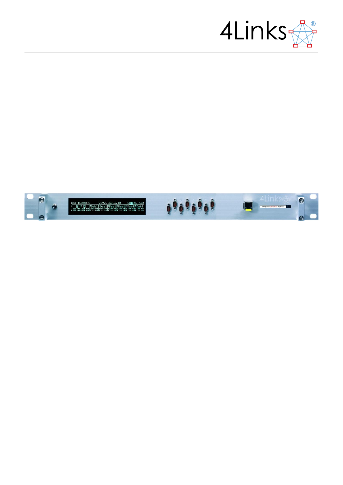
3.5. The RG408 Hardware Platform .......................................................................................................................15
3.4.3 Handling and Transportation............................................................................................................. 16
3.4.4 RG Platform Firmware ....................................................................................................................... 16
4 Block Diagram ................................................................................................................................................... 17
5 User Interface ................................................................................................................................................... 17
5.1 Initial (Power-up) display............................................................................................................................17
5.2 Normal (Status) display ..............................................................................................................................18
6 Front Panel Interaction..................................................................................................................................... 20
6.1 IP address....................................................................................................................................................22
6.2 Time Synchronisation .................................................................................................................................23
6.3 Health Display.............................................................................................................................................23
7 DSI Option Details............................................................................................................................................. 25
8 Option ER –Event/Error Reporting................................................................................................................... 25
9 Option TT –Time Tags ...................................................................................................................................... 25
10 Option EI –Event/Error Injection...................................................................................................................... 26
11 Option EW –Event/Error Waveforms............................................................................................................. 27
11.1.1 SpWIO Event Waveform Defaults.................................................................................................... 30
11.1.2 SpWIO Event Waveform Examples ................................................................................................... 30
12 Option SO –Synchronised Outputs .................................................................................................................. 31
13 Option CO –Controlled Outputs....................................................................................................................... 33
14 Option OD and OE –Output Disable and Output Enable ................................................................................. 34
15 Unit –to –unit Time-Tag Synchronisation ....................................................................................................... 35
15.1 Setting the Synchronisation Source............................................................................................................36
16 Software............................................................................................................................................................ 38
16.1 Files Supplied with the DSI .........................................................................................................................38
16.2 Controlling the DSI using the SpWIO Program.........................................................................................38
16.3 The RMAP plugin for the SpWIO Program ...............................................................................................39
16.4 C-language Application Programming Interface ........................................................................................39

Page 5
16.5 Waveform Handling....................................................................................................................................39
17 Troubleshooting Guide ..................................................................................................................................... 40
17.1 I cannot make a TCP/IP connection to my DSI unit....................................................................................40
17.2 I cannot send to, or receive from, one of the DSI unit’s SpaceWire ports.................................................41
17.3 My SpaceWire link(s) are disconnecting unexpectedly..............................................................................41
17.4 My API program hangs at start-up! ............................................................................................................41
17.5 My API program works for a while and then hangs... ................................................................................42
17.6 Ethernet Performance in large networks ...................................................................................................42
17.7 Waveform capture offset from event ........................................................................................................42
18 Regulatory information..................................................................................................................................... 43
18.1 EU................................................................................................................................................................43
18.2 USA .............................................................................................................................................................43
18.3 Waste Disposal ...........................................................................................................................................43
18.4 Restriction of Hazardous Substances .........................................................................................................43
19 FMECA............................................................................................................................................................... 43
20 Electrical / Mechanical Characteristics............................................................................................................. 43
20.1 Physical .......................................................................................................................................................43
20.2 Environment ...............................................................................................................................................44
20.3 Power Supply..............................................................................................................................................44
20.3.1 Power Consumption .......................................................................................................................... 44
20.3.2 Grounding for Electrical Safety.......................................................................................................... 44
20.3.3 Fuse Protection.................................................................................................................................. 44
20.3.4 Power Connector............................................................................................................................... 45
20.4 SpaceWire Connector Pinouts....................................................................................................................45
21 Statement of Volatility...................................................................................................................................... 47
21.1 Removing all information from a Unit........................................................................................................47
21.2 Security Notice............................................................................................................................................47

Page 6
1Introduction
The 4Links Diagnostic SpaceWire Interface (DSI) is a rack-mounted transparent interface that allows SpaceWire
packets to be sent and received over Ethernet via a TCP/IP socket connection. It provides remote access to a
SpaceWire network for software simulation of devices, remote monitoring and distributed system integration
activities. In addition, it provides for the detailed analysis of SpaceWire components, including routing switches.
Each packet received may be time-tagged to a resolution better than 2ns. There is no limit to the length of the
SpaceWire packets that can be transferred. Abnormal data ("errors") may be injected and monitored. The low-
level SpaceWire link start-up and operating behaviour may be modified for diagnostic purposes. Concurrent
outputs on several links may be synchronized. Waveform captures of the SpaceWire link signals may be triggered
by a very wide set of events.
The Ethernet port provides a galvanically isolated connection with a cable length of up to 100m. Attaching this to
the Internet allows world-scale connections.
Ethernet and TCP/IP provide a standard interface mechanism that is supported by all major operating systems, so
no additional software drivers are required.
The basic DSI-RG408 unit provides data transfers and may be extended with options to provide for time codes,
event reporting, waveform capture and time-tags. Most options can be added as a simple field upgrade by
replacing the removable memory card on the front panel of the unit.
This equipment is available with two, four or eight active ports which may be mounted on the front panel (see the
picture above) or on the rear panel.
1.1 Product Features
Feature
Description
1U support
3U support
SpaceWire
SpaceWire Link rate (Mbps)
400Mbps
400Mbps
Ethernet
Ethernet Speed
1Gbps
1Gbps
Ports
Number of SpaceWire ports
2/4/8
2
Power
Input supply to unit
24V DC @48W
12V DC @15W
1.2 Product Options
Option
Description
1U support
3U support
TT
Time Tags
Option
No
ER
Event/Error Reporting
Option
Standard
EI
Event/Error Injection
Option
Standard
EW
Event/Error Waveforms
Option
Standard
SO
Synchronised Outputs
Option
No
CO
Controlled Outputs
Option
No
OD
Output Disable
Option
No
OE
Output Enable
Option
No

Page 7
2Operation
This section describes the main features of the Diagnostic SpaceWire Interface.
The Diagnostic SpaceWire Interface (DSI) is a high-performance Ethernet-to-SpaceWire Bridge that can relay
traffic from a single TCP/IP Ethernet connection to up to eight concurrently-operating bidirectional SpaceWire
ports.
The DSI may be purchased with firmware that supports fewer than the eight SpaceWire connectors on the RG408
hardware platform. In this case, only the lowest-numbered SpaceWire connectors are
usable - e.g. ports 1 and 2 for 2-port firmware and ports 1-4 for 4-port firmware. The remaining ports are
disabled. Firmware upgrades to enable further ports are available from 4Links Limited.
2.1 General
The DSI is connected to an Ethernet network and passively waits for a connection from a host computer. It is
identified by an IP address that is used by the host computer to make this connection.
The connection is made using a TCP socket, which is flow-controlled and is capable of recovering from errors that
might occur on the network between the user and the EtherSpaceLink unit.
Upon making the connection, the DSI is set to a known state with the SpaceWire links disabled, the
link speed set to 10Mb/s and all the options reset. The user program must enable the SpaceWire links before data
can be sent or received. Once enabled, data is transferred, transparently, from the
SpaceWire link to the application program on the host, and also from the program to the SpaceWire link.
There is no limitation on the size of packet transfers in each direction - not even as a result of finite buffer sizes.
The user has complete control over the SpaceWire packet content and structure; a packet may be sent or
received in segments.
The host program can also control the transmission speed of the SpaceWire links. The transmit speed can be
changed at any time, including in the middle of a packet. Speed changes are transparent and do not require link
disconnection. In accordance with the standard, the SpaceWire links always start at 10Mb/s and then, when the
link(s) are established, they may be changed to the user-selected speed. All of the links on the DSI run at the same
user-selected speed, except for any that are selected to remain at the initial 10Mb/s rate.
Disconnection of the user’s program from the DSI results in the SpaceWire links being disabled and all of the DSI
options being reset.
The DSI can therefore be seen as a transparent interface - when the user program activates theSpaceWire links,
they can connect to the target SpaceWire network, and when the user program is stopped, the SpaceWire links
disconnect.
The Diagnostic SpaceWire Interface may be operated in three ways:

Page 8
By its operator from their computer keyboard, using a supplied program to generate and monitor
SpaceWire traffic manually;
Through the use of pre-designed command scripts that run standard sets of tests and analyse the results
automatically;
Using customer-created software that interacts with their SpaceWire network through the
EtherSpaceLink Application Programming interface (API) under program control.
2.2 Getting Started
As an Ethernet-to-SpaceWire bridge, the primary purpose of the Diagnostic SpaceWire Interface is to relay traffic
from a host computer to one or more SpaceWire ports, and vice-versa. This can easily be demonstrated by
connecting port 1 of the DSI back to itself using the supplied loop-back connector:
FIGURE 2-1CONNECTING THE DSI IN LOOP-BACK MODE
Using the SpWIO program, a SpaceWire packet may be sent from the host computer to the DSI’s SpaceWire port
1, from where it flows through the loop-back cable and back to port 1. From there, it will be returned to the host
computer, displayed and recorded.
Here we can see that a 4-byte EOP-terminated packet was transmitted to port 1 of the DSI, and a 4-byte packet
was then received from port 1.
Further examples in this manual will illustrate some of the advanced error-injection, error-reporting and
synchronisation features of the Diagnostic SpaceWire Interface.
2.3 Standard Diagnostic SpaceWire Interface Capabilities
All DSI units include the following capabilities:
java -jar SpWIO.jar /u 192.168.3.42
//-4Links.SpWIO (v24:20111201/v33:20110920) on Fri Sep 14 14:48:04 BST 2012
//-/u 192.168.3.42
//-Attached 192.168.3.42 is DSI-RG40x/8 v1.9 [EI,EW,ER,TT,SO], 8-ports,
//- link mode is normal at 10.0Mb/s
//-Log file is "SpWIO_20120914_144809.log"
//-Input from "(console)"
@1 2 4 6 8 eop
Tx:@1 #02 #04 #06 #08 EOP
Rx:@1 #02 #04 #06 #08 EOP

Page 9
Bridging of bidirectional streams of characters from Ethernet to SpaceWire;
The ability to support up to eight concurrently-active SpaceWire ports, depending on the configuration
purchased;
The transmit speed of the links can be set at up to 400Mb/s in steps of 1Mb/s or less;
The receive speed of the links is in excess of 400Mb/s;
Software is provided for the manual and scripted generation of SpaceWire traffic, together with a C-
language programming API for automated testing.
2.4 DSI Options
A Diagnostic SpaceWire Interface can be supplied with firmware that provides additional optional features.
Detailed information about these options can be found in section 7, “DSI Option Details”.
2.4.1 ER - Event / Error Reporting
Tokens defined as errors, that would normally be hidden (typically resulting in a link reset) and replaced by (at
most) an EEP character, can be made visible to the user. Correct, but normally hidden tokens (such as flow-
control tokens) can also be transferred to the user.
2.4.2 EW- Event / Error Waveforms
Each SpaceWire port has an associated waveform store that captures transmit and receive wire signals for that
port. Waveform captures can be triggered on a wide variety of events on that and/or other ports. It is possible,
for example, to capture wire signals for all ports after a trigger signal on one port.
Triggers include all error conditions, received data, lifting of the synchronised outputs barrier, signals on the
external SMA connectors, and user-inserted flags in the transmit data stream.
2.4.3 EI - Event / Error Injection
SpaceWire tokens that are not normally generated, because they are defined as errors, can be explicitly
inserted into the data stream:
Parity error between tokens
ESC-EOP - escape end-of-packet
ESC-EEP - escape error-end-of-packet
ESC-ESC - escape escape
Idle periods - when D and S remain constant. An extended idle period (greater than the SpaceWire
disconnect timeout, which is nominally 850 ns) should trigger a SpaceWire timeout response.
These error injection functions allow the user to determine the behaviour of SpaceWire components under
controlled error conditions.
The EI option also allows the flow-control behaviour of the SpaceWire state-machine to be altered to provoke
behaviour and errors relating to flow-control. For instance, flow-control tokens may be withheld, either partially
or completely, to explore a device’s handling of low flow-control credit. Alternatively, too many flow-control
tokens can be issued, which should eventually result in a SpaceWire error condition.

Page 10
2.4.4 TT - Time-tags
Selected events can be time-tagged with a resolution of better than 2 ns. All of the DSI’s ports use the same time
reference, so that relative time-tags between ports are consistent.
With option SO, Synchronized Outputs, it is also possible to accurately measure round-trip times for data.
Multiple EtherSpaceLink units can be linked so that their time-tags are synchronized to allow comparisons of
time-tags generated on multiple units.
DSI Version 1.0 introduced optional delta time-tags. When enabled, time-tags occurring shortly after another
time-tag (on the same link) are reported as delta times. Long intervals (>∼6.5us) result in the usual absolute time-
tag. Delta time-tags are coded using 2-bytes instead of the usual 8-bytes and thus considerably reduce traffic
when time-tags are used with high speed data.
2.4.5 SO - Synchronized Outputs
In order to test functions such as the arbitration in a routing switch, it is necessary to present inputs to the
device-under-test that are synchronized with each other. The Synchronized Outputs option allows
outputs from all or any sub-set of the ports to be synchronized at user specified points in their data streams. For
example, multiple packets may be scheduled to start their transmission at the same time, or one packet may be
started at the same time as another finishes.
From a single DSI, output synchronization is to within 2 ns.
Multiple units can be linked so that their outputs are synchronized between units as well as within.
2.4.6 CO - Controlled Outputs
It is possible to synchronise the transmission of any character in the transmit stream to an external clock
transition by using the CO option.
Low-to-high transitions on a rear-mounted SMA connector permit the transmission of traffic beyond each HOLD
character that is inserted in the transmit data stream.
Each port on the DSI has a transmit buffer of approximately 32 kbytes, which stores data characters, EOP tokens
and HOLD markers.
2.4.7 OD and OE - Output Disable and Output Enable
When testing delicate or valuable SpaceWire hardware, some users might prefer to disable all of the SpaceWire
signals from the DSI when their test system detects an abnormal condition.
The DSI’s Output Disable option (OD) responds to a high-level input signal on SMA connector pair J3-J4, and tri-
states the SpaceWire ports. When J3-J4 is not driven, the DSI behaves as it normally would.
Conversely, the DSI’s Output Enable option (OE) only enables its SpaceWire outputs when a high-level input signal
is present on SMA connector pair J3-J4, making it fail-safe. The drawback to this option is that the DSI will appear
inert unless J3-J4 is driven high, which is a non-standard behaviour.
The OD and OE options indicate “-3S-” on the DSI unit’s front-panel when its SpaceWire outputs are tri-stated.

Page 11
2.5 Front-Panel Display
The front panel display continuously monitors and displays the states of the Ethernet and SpaceWire links. The
top line of the display shows the product number, the current IP address of the EtherSpaceLink unit, and the
name “4Links” on the right.
FIGURE 2-2 THE DSI DISPLAY
2.5.1 Ethernet Information
Information about the remote Ethernet connection is shown on the upper section of the display. The status of the
Ethernet connection is provided, together with indications of when Ethernet transmit and receive activity occur.
2.5.2 SpaceWire Information
Information about the SpaceWire links is shown on the lower section of the display. The speed of transmission
and reception on each link is shown, and any receive or transmit activity is indicated.
2.5.3 Communication Protocol
4Links EtherSpaceLink units provide access to a SpaceWire network from computers on a conventional TCP/IP
Ethernet network. TCP/IP is used over Ethernet to provide an error checked guaranteed delivery system, even
through noise or the intervening network failing and being restored (for example, a cable being removed and
reconnected).
In many circumstances, the EtherSpaceLink units will be controlled using 4Links-supplied software, such as
SpWIO. At other times, the EtherSpaceLink units may be driven by user-written programs that use the
Application Programming Interface (API) provided. Access via the Native Interface is also possible.
Communication over Ethernet uses a TCP/IP socket connection and the EtherSpaceLink library routines then
convert the traffic to SpaceWire.
This may be seen as a hierarchy of protocols:
FIGURE 2-3 CONNECTION OF A SPACEWIRE DEVICE TO A COMPUTER USING AN ETHERSPACELINK UNIT

Page 12
In the event of an EtherSpaceLink unit being powered down, the computer will continue to expect the connection
to be restored, but the EtherSpaceLink unit will have lost connection information and the computer application
program will have to be restarted.
Similarly, a failure of the computer will leave the EtherSpaceLink unit waiting for a connection restoration that is
not possible, and in this case the EtherSpaceLink unit must be reset, by cycling power or by removing and re-
inserting the removable memory card on its front panel.
2.6 Programming API
User programs communicate with the TCP socket via an Application Programming Interface (API), provided in the
C programming language.

Page 13
3Specification
3.1 SpaceWire Links
The DSI’s SpaceWire links conform to ECSS-E-ST-50-12C (31st July 2008).
3.1.1 SpaceWire Receive Performance
Receive speeds may be in the range from 1.2Mb/s to more than 400Mb/s (the lower limit is set by the SpaceWire
disconnect timeout, nominally of 850 ns). The edge separation on the SpaceWire signal lines must be greater than
1.4 ns.
3.1.2 SpaceWire Transmit Performance
The transmit speeds of all of the links on a DSI unit are the same, except for those which are individually set to
EtherSpaceLink_LINK_mode_fixed_speed, which is the SpaceWire standard link start-up speed of
10Mb/s.
A wide range of user-selected transmit speeds is available from 1Mb/s up to 400Mb/s, with an increment of
1Mb/s or less dependent on the speed range, as shown in the following table.
Lower-speed (Mbps)
Increment (Mbps)
Higher-speed (Mbps)
40.0
1.0
400
4.0
0.1
39.9
1.0
0.01
3.99
3.1.3 SpaceWire Connectors
Eight standard 9-way Micro-miniature D-type SpaceWire socket connectors are mounted either on the front
panel (on RG hardware platforms) or on the rear panel (on
RG-R platforms).
The connectors are labelled 1 to 8, from left to right,
corresponding to software and API ports 1 to 8 respectively.
Pin
Direction
Signal
1
Input
+Din
2
Input
+Sin
3
Ground
4
Output
+Sout
5
Output
-Dout
6
Input
-Din
7
Input
-Sin
8
Input
-Sout
9
Input
+Dout

Page 14
The pinout of the SpaceWire socket connectors (looking from the outside of the EtherSpaceLink unit) is shown
above:
All eight of these signals are buffered within the DSI using LVDS buffers for each of the differential signal pairs.
Within the DSI, all signal grounds are bonded to the chassis of the unit. Notice that the ground potential
difference between each device-under-test must be held within each receiver’s input common-mode voltage
range.
3.1.4 SpaceWire Time Codes
SpaceWire defines a mechanism for transferring a global time reference across a network. The DSI can display
time-codes that are received from the network. It can generate time-codes from the host computer. It is not
equipped with a hardware time-code generator; only the 4Links ESL (EtherSpaceLink) and ATI (Absolute Time
Interface) have one of these.
3.2 The Ethernet Connection
An RJ45 socket, housed in an SFP module situated on the front panel, supports 1000Mb/s (1000BaseT) or
100Mb/s (100BaseT) full-duplex Ethernet connections over twisted-pair cable. The interface has an auto-
crossover function, allowing direct connection of the EtherSpaceLink unit to a computer or to an Ethernet hub or
switch, using either a standard or a crossover cable.
3.2.1 ICMP Echo (ping) Support
The DSI will respond to an ICMP echo request - as provided on many operating systems via the ping command.
This can provide a simple test to check that the unit is accessible on the network.
3.2.2 Full-Duplex Ethernet
Only full-duplex Ethernet connections are supported.
3.3 SMA Synchronisation Connectors
Synchronization (to other 4Links units or to external devices) is achieved using SMA connectors, on units with the
“-S” model number suffix where they are fitted.
The rear panel of a suitably-equipped DSI contains eight SMA connectors, labelled J1 to J8 from left to right when
looking at the rear panel, corresponding to software and API synchronization connections J1-J8 respectively.
9
8
7
6
5
4
3
2
1
FIGURE 3-1SPACEWIRE CONNECTOR PINOUT

Page 15
These connectors are used as four pairs, J1-J2, J3-J4, J5-J6 and J7-J8. Connector pairs J1-J2, J3-J6 or J7-J8 may not
be present on all platforms. Refer to the functions and options installed for details of their usage.
The outer conductor of each SMA connector is ground / shield, and the inner conductor carries the signal. The
two SMA connectors in a pair are internally wired to each other and may be used as a loop-through connection
for a 50Ω-terminated line. Alternatively, a 50Ω resistive terminator may be inserted into one of the connectors in
each pair so that the other forms a terminated connection.
FIGURE 3-2 SMA CONNECTOR LAYOUT
Connector pair J7-J8 is used on the DSI for time synchronisation; see section 15, “Unit-to-Unit Time-Tag
synchronisation”, for details.
3.4 Discovering a Unit’s Serial Number and Installed Product Options
A unit’s serial number may be read off its front panel display at boot time. Alternatively, click the toggle switch
upwards or downwards once to view the serial number of a running unit.
3.4.1 The Unit Serial Number and its relation to the Ethernet MAC address
4Links EtherSpaceLink unit serial numbers are of the form Annn (e.g. A202).
The least-significant bits of the Ethernet Media Access Control (MAC) address of a unit are directly related to its
serial number:
Serial numbers
MAC address
A1 to A4095
00-50-C2-21-20-01 to 00-50-C2-21-2F-FF
3.4.2 Installed Product Options
When viewing the serial number of a running unit, as above, the installed Product Options are listed as two-
character acronyms within square brackets.
For the illustration in figure 6.1, the options are CO, EI, EW, ER, TT and SO. See section xx, “DSI Options”, for
further information on the available DSI options.
3.5. The RG408 Hardware Platform
The RG408 hardware platform is supplied with eight SpaceWire ports and with front or rear mounted SpaceWire
connectors (RG408 or RG408-R, respectively).
The hardware is optionally available with SMA connectors for external synchronization (on the RG408-S). These
enable inter-box time-tag synchronization (on the DSI, SRR, MSR and ATI), as well as external triggers (on a DSI).

Page 16
The -L and -M suffixes indicate the FPGA size in an RG408 unit. The smaller FPGA is supplied in RG408-L units. An
Extra Resources “-M” option (on the RG408-M) supplies greater processing and memory facilities. This provides
for more than four ports on a DSI, for double the recording buffer memory on an MSR, and for more ports or
larger RMAP memories on an SRR.
3.4.3 Handling and Transportation
The 4Links RG platform products are designed to be robust, and are capable of being transported to support
SpaceWire testing.
Units should be packaged in protective foam or similar material to prevent them from being subjected to
excessive shocks during handling.
Units should not be subjected to condensation; transferring them directly from a cold shipping container to a
moist warm laboratory atmosphere is not recommended.
The micro-miniature D-type SpaceWire plugs and sockets are fragile. Connections should be made with care. If
the units are in an environment where they are frequently re-connected, consideration should be given to the use
of sacrificial connectors or an external router (such as the 4Links Flexible SpaceWire Router).
3.4.4 RG Platform Firmware
Firmware for the 4Links RG platform products is supplied on CompactFlash memory cards. These
cards may be hot-swapped - i.e. plugged and unplugged from a live unit. RG Platform units boot from an installed
memory card when they are powered up, as well as when they detect that a memory card has been newly-
inserted. Ejecting and then re-inserting a memory card is therefore an acceptable method of re-booting a unit.
A memory card may be ejected by pressing the eject button on the right-hand side of the card slot with a non-
conductive device.
CAUTION:
Do not attempt to remove the memory card using a conductive object (e.g. a pen or a screwdriver).
Memory cards are configured for a particular 4Links hardware platform, and are only intended for use with that
unit. If one attempts to boot a 4Links unit with a memory card that was built for another unit, or with a non-
4Links memory card, then the boot self-test display will display a failure message at the fifth step - which
indicates that the card is unsuitable for this unit.

Page 17
4Block Diagram
The elements that make up an EtherSapceLink family unit are shown below.
5User Interface
5.1 Initial (Power-up) display
The front-panel display will initially show the unit proceeding through self-test and configuration, leading after a
few seconds to a normal operational display.
FIGURE 5-1 THE RG408 POWER-UP DISPLAY
FPGA board, containing:
Ethernet TCP/IP interface
SpaceWire Link interfaces
Transmit and receive buffers
RJ45 Ethernet
SFP module
8 SpW ports
micro-D
Power Supply
22-50V DC
Synchronisation
SMA connectors
System Status
Thermal/health
System Controller
microcontroller
Configuration data
CF Card
User Interface
Front panel display/switch

Page 18
Failure during the initial four stages of the self-test usually indicates a hardware problem. Failure at the fifth stage
suggests a fault with the contents of the memory card; memory cards are configured for specific 4Links units, so
make sure that you have plugged the correct card into this unit.
5.2 Normal (Status) display
In normal operation, the display shows the state of the SpaceWire and Ethernet connections and any activity on
these interfaces.
FIGURE 5-2 THE DSI STATUS DISPLAY
The top line of the display shows Ethernet information:
The IP address of this unit;
Ethernet status:
∗The SFP module (see section 3.2, “The Ethernet Connection”) is not present;
X The SFP module is present but the Ethernet cable is not connected;
L The Ethernet is connected and the DSI is listening for a connection;
C The Ethernet is connected to a user program.
Ethernet Activity (note that Ethernet activity that is not related directly to SpaceWire traffic may be
reported, e.g. broadcasts from other devices on the Ethernet):
R Data is being received from Ethernet;
T Data is being transmitted to Ethernet.
The lower section of the display shows SpaceWire information:
SpaceWire link status and activity:
Dsbl The link is disabled;
Wait The link is waiting for a connection (legacy mode);
Dsct The link is disconnected (ECSS mode);
-3S- The link has been tri-stated by the Output Disable (OD) or Output Enable (OE) options. See
section xx, “Options OD and OE - Output Disable and Output Enable”, for further information on
these.
R Data has recently been received;
T Data has recently been transmitted;

Page 19
R A time-code has recently been received;
T A time-code has recently been transmitted.
N A null has recently been received;
F A flow-control token has recently been received;
X A timeout has recently occurred;
P A parity error has recently occurred.
Each of these status indication characters is displayed for a brief duration to make them visible to the human
eye.
Some common SpaceWire conditions may be easily recognised, e.g. “NX” (nulls and timeouts) will be seen
coming from a link that is trying (but failing) to establish a connection; “N” is shown continuously for an
established but idle connection, etc.
Transmit link speed;
Receive link speed, if connected.
The above display shows that two of the SpaceWire links are connected at 100Mb/s, that the unit will respond to
IP address 192.168.3.40, that the Ethernet port is connected, and that the unit is connected to a remote host
computer.

Page 20
6Front Panel Interaction
A centre-biased three-position toggle switch is located to the left of the front panel display. This is used to show
the unit’s serial number and options, and to set the unit’s IP address.
Settings are stored in non-volatile memory and are restored when the unit is next powered-up.
A single movement of the switch, either upwards or downwards, enters the first step of the user interaction
where the unit’s serial number and option list is displayed. It is possible to return to the normal display by moving
the switch a second time in the same direction, or to inspect and/or set values by moving the switch a second
time, but in the opposite direction. Doing nothing will, after a few seconds, cause the display to return to normal.
Messages on the screen indicate the effect of moving the switch upwards (top line, left side) or downwards
(bottom line, left side).
After pushing the switch down, we see (for DSI serial number A260 with all options) that its clock is not yet
synchronised to other EtherSpaceLink units, that it is connected to a 100Mb/s Ethernet, and that no user program
is connected to it:
FIGURE 6-1 THE DSI SERIAL NUMBER AND CONFIGURATION DISPLAY
The chart below shows how to navigate the settings menus.
The current state is shown as a box with three sections. The top section shows a label that indicates the effect (if
any) of pushing the switch up. The middle section describes what is displayed. The bottom section shows a label
that indicates the effect (if any) of pushing the switch down.
FIGURE 6-2 FRONT PANEL NAVIGATION
The state is entered via an arrowed line into the top or the side of the box. A line from the top section traces flow
to the next state when the switch is pushed up. A line from the bottom section traces flow to the next state when
Table of contents
Other 4Links Recording Equipment manuals