4ms EnvVCA User manual

EnvVCA
4ms Company
User Manual 1.0 – August 22, 2022
The EnvVCA is an analog envelope generator, slew limiter, and VCA.
EnvVCA features:
•Versatile linear envelope generator/LFO
•Low-noise, low-distortion, DC-coupled exponential VCA
•100% analog
•Sliders, switches and Time CV jack controls Rise and Fall times
•125µs (8kHz) to over 30 minutes
•With sliders and switches only: ~1.25ms (800Hz) to over 2 minutes
•Independent attenuverters for Rise and Fall time
•Blue/red LEDs indicate strength and polarity
• Cycle button for looping envelopes (LFO)
• Trigger input jack fires a one-shot envelope
• Cycle gate input jack toggles cycling
• EOR (End of Rise) gate output can be used to chain and sequence events
• Env Level slider controls output level of the Env jack without changing the VCA volume
• Audio In and Out jacks for passing audio or CV through the VCA
• VCA gain internally connected to envelope output
• Follow input jack allows for slew limiting, sustain (ASR), and exotic filtering effects
• Re-trig jumper allows for re-triggering during rise phase

Table of Contents
Setting up your EnvVCA
1. Power off your Eurorack system.
2. On the back of the EnvVCA you will see a 10-pin header. The 10-pin
header connects to a Eurorack power header using the included power
cable. Connect the 16-pin end of the power cable to a 16-pin Eurorack
power header on your power supply distribution board and the 10-pin end
to the EnvVCA with the red stripe on the power cable oriented towards
the bottom of the module.
3. Using the included screws, securely attach the EnvVCA to the rails of
your case.
4. Power on your Eurorack system.
Note: The EnvVCA is reverse-polarity protected, but incorrectly connecting
any module in any system can damage other modules on the power bus.
Setting up your EnvVCA! "........................................................................................2
Controls and Jacks! "................................................................................................3
Patch: Making Notes! ".............................................................................................5
Making Notes (basic)! ".......................................................................................5
Making Notes Using External Triggers! ".............................................................5
Patch: Ratcheting! "..................................................................................................6
Ratcheting! "........................................................................................................6
Advanced Ratcheting! ".......................................................................................6
Rise and Fall Time Ranges! "....................................................................................7
Creating Envelopes (Trigger, Cycle, Follow)! "...........................................................7
Triggering with RETRIG Jumper Off (Factory Default)! ".....................................7
Triggering with RETRIG Jumper On! ".................................................................7
Cycle Button/Jack! "...........................................................................................8
Follow Jack with Gates! "....................................................................................8
Fundamentals of the Follow Jack! "..........................................................................9
Creating ASR and ADSR Envelopes! "......................................................................9
ASR envelope! "..................................................................................................9
ADSR envelope! "..............................................................................................10
Audio filter! "......................................................................................................11
Portamento/glide! "...........................................................................................11
Generating Exponential and Logarithmic Envelopes! "...........................................11
RETRIG Jumper! "...................................................................................................12
VCA Min Gain Trim pot! "........................................................................................12
Electrical and Mechanical Specifications!............................................................12
Page of2 12

Controls and Jacks
Cycle Button, LED and Cycle Jack
The Cycle button toggles the cycling state. When cycling, the EnvVCA behaves
like an LFO, with an output waveform that continuously rises and falls. The
button illuminates orange to indicate the module is cycling. Note that pressing
this button does not reset or alter an envelope that’s already rising or falling.
The Cycle jack toggles the cycle state using a gate source. If the Cycle button
is off, a given gate signal will initiate cycling for as long as the gate is held high.
If the Cycle button is on, then the functionality is inverse and the gate signal will
cease any cycling for as long as the gate is held high. See Using the Cycle
Button for more information.
Rise/Fall Sliders
The Rise and Fall sliders control the rise and fall times of the envelope. Shifting
a slider up makes the rise or fall portion slower, and down makes it faster.
Each slider has a white light that indicates the current stage and output voltage
of the envelope. When the envelope is in the rise stage, the Rise slider light will
increase in brightness until the envelope hits its maximum. Once the peak is
reached, the Rise light will turn off and the Fall light will turn on, decreasing in
brightness as the envelope falls.
Rise/Fall Switches
The Rise/Fall switches select the overall range of the sliders. Each slider has its
own switch with three positions: Fast, Med, Slow.
When the switch is flipped to Fast, the envelopes go well into the audio range,
allowing for classic AM, FM, and other fast modulation effects.
The middle position (Med)is designed for typical musical tempos, and can be
useful when using the VCA to make notes at common BPMs.
The Slow position is geared for gradual fades and other slow LFO-style
modulations.
See the Rise and Fall Time Ranges chart on page 7 for more information.
Time CV Jack and Rise/Fall CV Knobs
The Time CV jack modulates the Rise and Fall times of the envelope. The jack
feeds two knobs: Rise CV, and Fall CV. Each of these knobs is an attenuverter
(short for “attenuating inverter”) and controls how much the control voltage on
the Time CV jack will effect either the rise time or the fall time.
Turning an attenuverter knob to the right of center means that a positive voltage
on the Time CV jack will lengthen the rise/fall time and a negative voltage will
shorten the rise/fall time.
Turning a knob to the left of center gives the opposite effect, meaning that a
positive voltage on the Time CV jack will shorten the the rise/fall time, while a
negative voltage will lengthen these durations.
The farther you turn the knob from center in either direction, the more effect
incoming CV will have. When the knob is centered, the signal on the Time CV
jack will have no effect on the rise or fall time.
Next to each knob is a light which indicates the strength and polarity of the
modulation. The light will turn blue when the rise or fall time is being lengthened
by CV, and red when the time is being shortened. The brighter the light, the
more of an effect the CV is having. When the light is off, the Time CV jack has
no effect on the envelope time.
See CV Controlling Rise and Fall Times and Generating Exponential and
Logarithmic Shapes for more information.
Page of3 12
Cycle
Cycle
Rise Fall
Slow
Fast
Fast
Med
Slow
Rise CV Fall CV
Time CV

Env Jack
The Env jack outputs the envelope. The level (amplitude) is attenuated by the
Env. Level slider.
Env. Level Slider
The Env. Level slider attenuates the envelope output on the Env jack. When
the slider is at the bottommost position, the Env jack will output 0V. In the
topmost position, the Env. jack will output an envelope between 0V and 10V.
The light on the Env. Level slider indicates the amplitude of the envelope on the
jack.
Note that the slider does not effect the envelope going to the internal VCA. If, for
example, the Env jack is patched to a modulation input on an external module
while audio is running through the VCA, the slider can be used to control the
amount of modulation without changing the audio level.
EOR Output Jack and LED
The EOR jack outputs a gate that goes high when the rise stage ends, which is
when the fall stage begins. The gate remains high as long as the envelope is
falling and goes low when the envelope completes. The jack will stay low when
the envelope is not running, and the light will shine orange when the EOR output
is high.
Audio In and Out Jacks
The Audio In and Out jacks are the input and output of the VCA. The envelope
output (pre-level slider) is internally routed to the CV input of the VCA. When the
envelope is stopped or at 0V, the Out jack will output silence. As the envelope
rises, the signal will get louder until it becomes as loud as the input signal at the
peak of the envelope. As the envelope falls, the signal will fade back to silence.
Trigger Jack
The Trigger jack requires a trigger of at least 2V to start an envelope. If there is
no envelope in progress, then a trigger will initiate a single complete envelope. If
the envelope is rising when a trigger is received, then the trigger is ignored
(unless the RETRIG jumper is installed, see below). If the envelope is falling
when a trigger is received, it will begin rising from its current voltage.
On the back of the module is a RETRIG jumper. When this jumper is installed,
the envelope will immediately jump to 0V and start rising any time a trigger is
received. This can cause a click on the VCA output, so the jumper is not
installed at the factory.
Follow Jack
The Follow jack is the input of a slew limiter, and can also be used for complex
envelope generation, exotic audio filtering, and envelope following.
Whenever the internal envelope is not triggered or cycling, the envelope output
will rise or fall in order to match the voltage level present on the Follow jack.
However, the rate of rise and fall times is limited by the positions of the Rise/Fall
sliders and the CV amounts. That is, the envelope output will try to “follow” the
signal present on the Follow jack, but it can only rise and fall as fast as the
envelope would rise/fall if it were to be triggered. Since “slew” is the rate of
change, we call this “slew limiting”.
Slew limiting can be used to create complex envelopes (ASR, ADSR, etc) by
timing the signal on the Follow and Trigger jacks. See Fundamentals of the
Follow Jack on page 9 for more information.
Page of4 12
Env. Level
EOR
Follow
Trigger
Audio
In Out
Env

Patch: Making Notes
Making Notes (Basic)
Patch a sound source into the Audio In
jack, and patch the Audio Out jack to your
mixer or amp so you can hear it on
speakers or headphones. When choosing
the sound source, try to find something that
makes a continuous tone or drone, such as
a VCO like the Ensemble Oscillator.
When Cycle is on (button is shining
orange), you should hear notes being
played at a steady tempo. The notes should
have a sharp attack (quick fade-in) and
longer decay (slower fade-out).
Try moving the Rise slider up and listen to
how the sound fades in more slowly. Then
move the Fall slider down and hear how the
fade-out gets faster. Continue to experiment
with the slider positions, listening to how the
sound and tempo changes. Try flipping the
switches to Fast and hear how much faster
the envelope gets.
Next, patch the Env jack to a modulation
input on the sound source. For example, if
you’re using the Ensemble Oscillator, try
patching it to the Warp jack. For other
VCOs, try a PWM or wave-shaper input.
Adjust the Env. Level slider to control the
amount of modulation. When the slider is all
the way down, you should have no
modulation.
Making Notes Using External Triggers
So far in this patch, the tempo of notes has
been linked to the rise and fall times of the
envelopes. It’s not possible, for example, to
have short, quick notes at a slow tempo.
By turning Cycle off, we can use the
Trigger jack to control the tempo with an
external module.
See the patch on the left. Press Cycle to
turn it off. The sound should stop. Patch a
clock or trigger sequence into the Trigger
jack. You could use the output from a clock
module like the QCD, RCD or SCM, or
perhaps the gate output of a sequencer.
You could even use an LFO waveform such
as a sine wave, as long as the signal peaks
are greater than 2V.
When the Trigger jack receives a trigger,
the envelope will fire one time. Play with the
external module’s tempo to hear how the
notes keep their shape at all tempos. You
can even make the notes “run together” by
setting the tempo faster than the note
duration.
Page of5 12
To mixer/
output
amp
Rise Fall Env. Level
Rise CV
Fast
Med
Slow
Slow
Fast
Fall CV
Audio
Cycle
Cycle
Follow
Trigger
Time CV
EnvVCA
Env
EOR
In Out
From sound
source
(e.g. a VCO)
Cycle on
Switches set
to Med
Rise slider
at Fast,
Fall slider
in middle
(adjust to
taste)
Optional:
To VCO
modulation
input
Optional:
adjust
amount of
modulation
Rise Fall Env. Level
Rise CV
Fast
Med
Slow
Slow
Fast
Fall CV
Audio
Cycle
Cycle
Follow
Trigger
Time CV
EnvVCA
Env
EOR
In Out
Cycle off
Clock or
trigger output
(e.g. QCD,
sequencer
gate out)

Patch: Ratcheting
Ratcheting
In this patch we’ll make a ratcheting effect
where the notes play at a steady tempo for
a while, and then periodically speed up in a
rapid burst.
Start with the Making Notes patch with
Cycle on and the Trigger jack unpatched.
Run the EOR out to the clock input of a
clock divider such as the RCD or QCD.
Patch the /8 (or any divided output) back to
the Time CV jack. Turn the Rise CV and
Fall CV attenuverters slightly to the left, so
that when the clock divider fires a pulse, the
notes play at a faster rate. If your clock
divider has an adjustable pulse width,
playing with that will change the duration of
the rapid bursts.
In this patch, the EOR jack fires rapidly
when the notes play faster, causing the
clock divider to receive more pulses. This
throws off the divider’s counting and makes
it hard to precisely set the timing and
duration of the bursts. For a more
controllable ratcheting effect, see the next
patch.
Advanced Ratcheting
Start with the patch above.
Turn off Cycle. Unpatch the EOR jack.
Make sure the clock divider is still running
(use another clock module to clock it if
necessary).
Patch the clock divider’s main or undivided
output into the Trigger jack.
Patch a divided clock signal into the Time
CV and the Cycle jacks, using a mult or
stacking cable. Make sure the divided clock
signal is slower than the clock going into the
Trigger jack. For example, if you’re using
an RCD or QCD for clocks, the /1 or
“=“ output should go to the Trigger jack,
and a /4 or /8 output should go to the Time
CV and Cycle jacks.
Keep the Rise/Fall CV knobs to the left of
center, as in the patch above.
Now whenever the clock divider’s /8 output
fires, the EnvVCA will cycle for the duration
of the gate at a rate set by the Rise/Fall CV
knobs.
Page of6 12
Rise Fall Env. Level
Rise CV
Fast
Med
Slow
Slow
Fast
Fall CV
Audio
Cycle
Cycle
Follow
Trigger
Time CV
EnvVCA
Env
EOR
In Out
To mixer/
output
amp
From sound
source
(e.g. a VCO)
Cycle on
Switches and
sliders set to
taste
From clock
divider
/8 output
To clock
divider
clock input
Rise/Fall CV to
the left
Rise Fall Env. Level
Rise CV
Fast
Med
Slow
Slow
Fast
Fall CV
Audio
Cycle
Cycle
Follow
Trigger
Time CV
EnvVCA
Env
EOR
In Out
Cycle off
From clock
divider output
(undivided)
Rise/Fall CV to
the left
From clock
divider
/8 output

Rise and Fall Time Ranges
Because of its analog nature, the maximum and minimum rise and fall times vary from unit to unit. The
table above shows typical values.
Note that the switch positions have little effect on the range obtained by using CV. This is intentional, to
allow external modules control over the full range.
Creating Envelopes (Trigger, Cycle, Follow)
There are four ways to generate an envelope with the EnvVCA: using
the Trigger jack, the Cycle button, the Cycle jack, or the Follow jack.
The Trigger jack starts an envelope when it receives a trigger. It only
responds to rising edges, that is, when the voltage rises through 2V.
Figure 1 shows how a long or short pulse will cause identical
envelopes since the pulse width and falling edge of the signal are
ignored.
Triggering with RETRIG Jumper Off (Factory Default)
If the envelope is already rising when a trigger is received, then the
trigger is ignored (unless the RETRIG jumper is installed). If the
envelope is falling when a trigger is received, it will begin rising from its
current voltage. Figure 2 demonstrates this: the fifth and seventh
triggers occur while the envelope is falling and cause it to begin rising mid-fall. The rest of the triggers
occur while the envelope is rising and are ignored.
Triggering with RETRIG Jumper On
Figure 3 shows how the RETRIG
jumper changes the behavior.
Regardless of what stage the
envelope is in, a trigger always resets
it to zero and begins rising. The sharp
transition to 0V can cause a click
when used with audio, so the jumper
is not installed by default.
Page of7 12
Switch Position
Slider
Range
(total env.
time)
Max Range
with CV
(total env.
time)
Use Cases
Slow
3 min. to
1.5 sec.
~30 min. to
300Hz
Gradual, slow fades or modulation changes
occurring over the course of a long time.
Med
20 sec. to
18Hz
~30 min. to
1kHz
Generally suited for typical musical tempos. Useful
for making notes, from snappy percussive sounds to
long decays. The slower slider settings approach
LFO ranges.
Fast
2.5Hz to
800Hz
~30 min. to
8kHz
Good for FM, AM or other audio-rate modulation.
Snappy attacks and sharp decays.
Fast
Med
Slow
Fast
Med
Slow
Fast
Med
Slow
Figure 1: Trigger jack pulse width
does not change Env output.
Figure 2: RETRIG jumper off.
Triggers on rise stage have no
effect. Triggers on fall stage switch
to rising.
Figure 3: RETRIG jumper installed.
Triggers always restart the envelope.

Cycle Button/Jack
The Cycle button is a simple way to initiate an envelope. When the button is on, envelopes will cycle
continuously. The button is latching, so pressing it once will make the module output envelopes until
you press the button again. Once an envelope begins, pressing the Cycle button again will not
immediately stop the envelope. Instead, the envelope will stop after finishing its fall stage.
The Cycle jack toggles the cycling state when a gate is received. It’s utilized in tandem with the Cycle
button. If the button is initially off, a gate signal at the Cycle jack will toggle it on. If the button is initially
on, a gate at the jack will toggle it off. The Cycle button will shine orange whenever the combination of
the Cycle jack and Cycle button causes the envelopes to cycle.
In Figure 4,the Cycle button is initially off, and the incoming gate signal on the Cycle jack causes the
envelope to cycle for as long as the gate is high. In this case, as the pulse width of the gate signal gets
wider, the EnvVCA outputs more cycles.
Figure 5 shows the opposite state; the Cycle button is initially on, so the incoming gate signal stops the
cycling for as long as the gate is high. In this case, as the pulse width of the gate signal gets wider,
there are longer pauses between groups of envelopes.
Note that the first pulse in Figure 5 does not stop the envelopes, and the three rapid pulses in Figure 4
only cause one envelope. This illustrates an important aspect of the EnvVCA: the state of the Cycle
jack and button only matter when the envelope is stopped (at 0V). Any combination of gates and button
presses while the envelope is running have no effect; it’s only when the envelope finishes running that
the Cycle jack or button can make it cycle again.
Follow Jack With Gates
Figure 6 illustrates the use of gates on the Follow
jack. A gate signal will cause the envelope to rise as
long as the gate is high. When the gate goes low,
the envelope will fall.
The fourth gate in Figure 6 shows that if the gate is
held high while the envelope reaches its maximum,
the envelope will hold (sustain) until the gate is
released. This is any easy way to create an ASR
envelope (Attack Sustain Release).
The short bursts of pulses at the end illustrate how
the Follow jack can be used to create complex
envelope shapes using only a sequence of gates.
The Follow jack can be used with more than gates, see Fundamentals of the Follow Jack for a detailed
discussion.
Page of8 12
Figure 4: When Cycle button is off, high gate on Cycle
jack makes envelope run.
Figure 5: When Cycle button is on, high gate on Cycle
jack makes envelope stop.
Figure 6: Sending gates into the Follow jack. When the
input gate goes high, the envelope rises; when the input
goes low, the envelope falls.

!
Fundamentals of the Follow Jack
The Follow jack causes the envelope to rise or fall in order to “follow” the signal on the jack. There are
two basic rules that govern this behavior:
Rule 1: If the voltage on the Follow jack is greater than the envelope voltage, the envelope will
rise; if the voltage on the Follow jack is less than the envelope voltage, the envelope will fall.
That is, the envelope will always “seek” the Follow signal: it will go up if the Follow signal is higher,
and it will go down if the Follow signal is lower. This is where the term “follow” originates.
Rule 2: The envelope can only rise and fall at the speed set by the Rise/Fall controls and CV.
This means that if the Follow jack suddenly jumps up (for example, when a gate is applied), the
envelope will try to follow that jump by rising, but it can only rise as fast as the controls allow it. The rate
of change, or slew, is limited, thus we call the Follow circuit a “slew limiter”.
Note that the term “envelope voltage” in Rule 1 refers to the internal envelope voltage, before the Env.
Level slider and Env jack output driver. Internally, the envelope has a maximum of 5V and minimum of
0V, which is why the Follow jack only responds to voltages from 0V to 5V. The Env jack’s output driver
doubles the internal voltage, so a 5V internal envelope corresponds to approximately 10V envelope on
the jack.
Armed with these two basic rules, we can now showcase some advanced uses for the Follow jack in
the following sections.
Creating ASR and ADSR Envelopes
ASR Envelope
An ASR (attack-sustain-release) envelope is trapezoidal,
with a rising slope (attack), a flat plateau (sustain), and a
falling slope (release). See Figure 7. The width of the
sustain stage is controlled by the width of the gate input:
holding the gate high longer results in more sustain. This is
in contrast to an AR (attack-release) envelope, which is the
triangular shape that results from patching into the Trigger
jack or using the Cycle button.
Patch the gate output of a CV/Gate keyboard to the Follow
jack and the Trigger jack, using a mult or stacking cable.
Patch an audio sound source into the Audio In jack, and
run the Audio Out jack to a mixer or amp.
If using a keyboard as a gate signal, tapping a key quickly
will result in a staccato note, while holding the key down
longer will result in a longer note. Keep in mind that the
minimum note length will always be determined by the rise
and fall time parameters, no matter how short the gate
input is.
Instead of a CV/Gate keyboard, you could also use the
gate output of a sequencer that has control over the gate
length (pulse width). Setting longer gate lengths for certain
notes will emphasize or accent them in the sequence.
This patch works because we patched the gate into both
the Trigger and Follow jacks. The Trigger jack ensures a
complete envelope will output even if the gate width is very
short. The Follow jack produces the sustain. If we had just
patched a gate into the Trigger jack, the envelope would
start to fall once the peak is reached and we would have
no sustain. However, if the gate at the Follow input is still
high, the envelope will remain high, creating the sustain
Page of9 12
Rise Fall Env. Level
Rise CV
Fast
Med
Slow
Slow
Fast
Fall CV
Audio
Cycle
Cycle
Follow
Trigger
Time CV
EnvVCA
Env
EOR
In Out
Cycle off
Gate signal
(CV/Gate
keyboard, or
sequencer with
gate width
control)
Rise/Fall
sliders and
switches to
taste
To mixer/
output amp
From sound
source

portion of the envelope. On the other hand, if we had only patched
into the Follow jack, then a short gate width would only produce a
complete envelope if the rise time parameter was very fast. Gates
that are shorter than the rise time will result in an envelope that
doesn’t reach the peak, as seen in Figure 6 of the previous section.
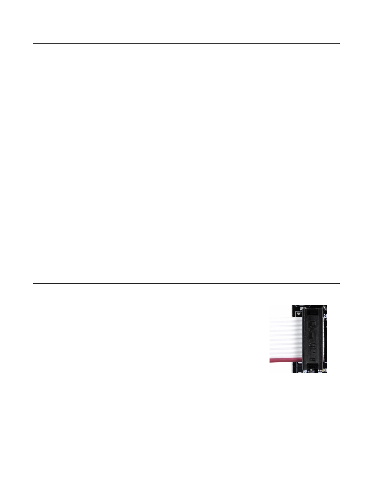
By patching the gate into both the Trigger and Follow jacks, we get
complete envelopes regardless of the settings, as seen in Figure 7.
Notice the width of the pulses and how they correlate to the sustain
of the envelope output. The first pulse is not wide enough to produce
any sustain because its width is lesser than the time it takes for the
envelope to rise.
ADSR Envelope
An ADSR (attack-decay-sustain-release) envelope is
like an ASR envelope, except that it adds a fourth stage
known as “decay” after the attack stage. After hitting
the peak, an ADSR envelope “decays” to a sustain
level less than the peak level. See Figure 8.This
sustain level and the speed at which the envelope
decays are controllable. The other stages (sustain and
release) are identical to those in an ASR envelope.
We can generate an ADSR envelope with control over
each stage by extending our ASR patch. This patch
requires a way to attenuate the gate signal. A fictional
attenuator module is shown on the left.
Start with the ASR patch from the previous section.
Unpatch the cable from the keyboard/sequencer gate
output going to the Follow input, and instead patch it
from the keyboard/sequencer gate output to the input
of the attenuator module. Patch the output of the
attenuator to the Follow jack.
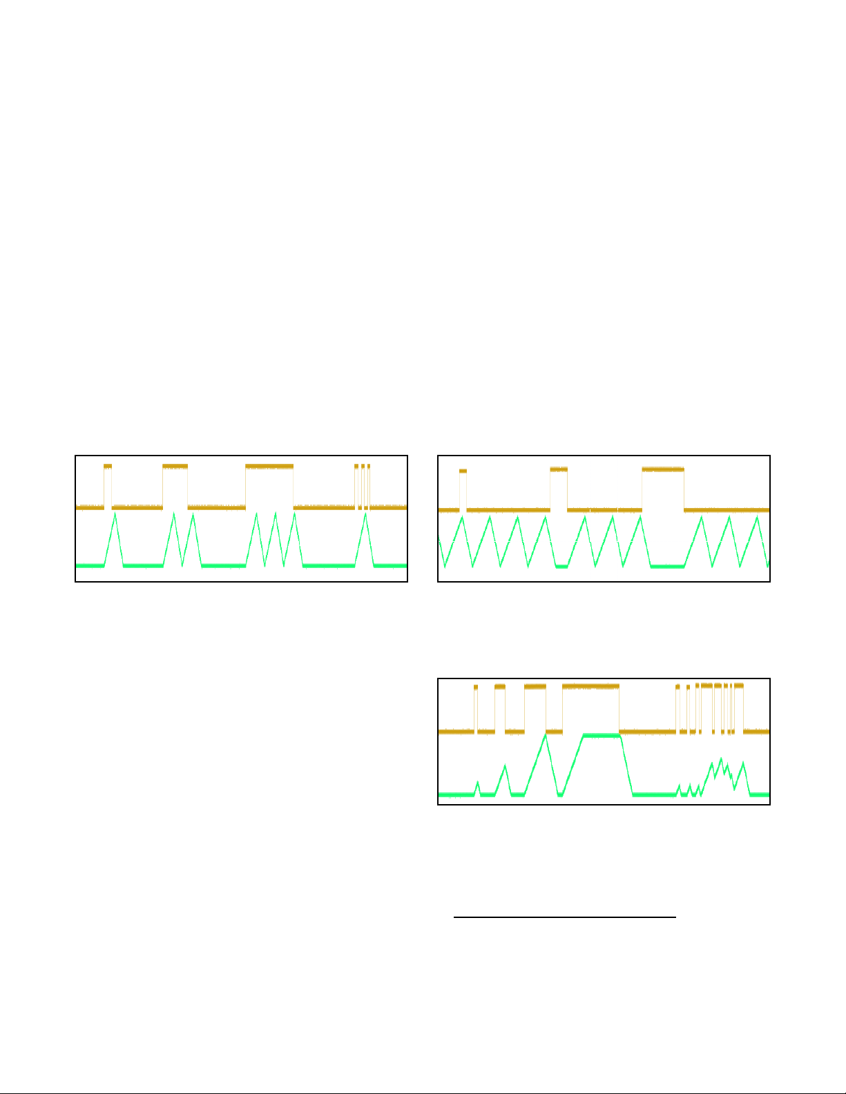
Firing a gate will generate an envelope as shown in
Figure 8. The rising edge of the gate will cause the
envelope to rise to its peak and then fall until it reaches
the level set by the Follow jack, which is controlled by
the attenuator knob. For example, setting the
attenuator knob such that the attenuator outputs a 3V
gate will make the envelope sustain at 3V internally
(resulting in a 6V sustain on the Env jack if the Env
Level slider is all the way up). After the gate on the
Follow jack goes low, the envelope will fall back to
zero during the “release” stage.
We now have control over the attack or rise speed
(Rise slider/switch), sustain length (gate pulse width),
and sustain level (gate attenuator). However the decay
time and the release time will always be the same, set
by the Fall slider/switch.
To make this a true ADSR envelope, patch a cable from
the mult or stacking cables on the gate output of the
keyboard or sequencer to the Time CV jack. Make sure
the keyboard/sequencer gate output still goes to the
Trigger jack and attenuator module input. Now you can
use the Fall CV knob to set the decay time relative to
the release time. Turning it to the left of center will
make the decay time faster than the release time, and
vice-versa. The reason this works is that the decay
stage occurs while the gate is high, and the release
Page of10 12
Figure 7: ASR patch: Gate length
controls sustain length
Rise Fall Env. Level
Rise CV
Fast
Med
Slow
Slow
Fast
Fall CV
Audio
Cycle
Cycle
Follow
Trigger
Time CV
EnvVCA
Env
EOR
In Out
Cycle off
Gate from
CV/Gate
keyboard or
sequencer
(width sets
sustain time)
Rise adjusts
attack
Fall adjusts
decay, release
time
To mixer/
output amp
From sound
source
Atten.
In
Out
Atten. sets
sustain level
Fall CV
adjusts decay
time
Figure 8: ADSR. Attenuator knob turned down in
2nd envelope to lower sustain level. Fall CV turned
up in 3rd envelope to make decay slower.

stage occurs when the gate is low. Since the gate is patched into the Time CV jack, the position of the
Fall CV knob only has an effect on the time when the gate is high, which is the decay stage. Note that
adjusting the Fall slider or switch will change both the decay and release times.
Audio Filter
The Follow jack can be used as an exotic audio low-pass filter by taking advantage of its slew-limiting
properties. First, the audio signal must be shifted up such that it’s within the range of 0V to 5V. Typically
a level shifter can be used to add the required DC offset. You may also need to attenuate the audio so
that it’s no more than 5V. Any signal outside this range will be clipped, resulting in harsh distortion.
Patch this adjusted audio into the Follow jack. Patch the Env output jack to your mixer/amp. Although
this patch passes audio, it doesn’t use the VCA section at all. To start, set the Rise/Fall sliders and
switches to the fastest positions. Send a steady positive voltage into the Time CV jack and turn the
Rise CV and Fall CV knobs all the way down.
At this point you should be hearing an audio signal that is similar to the original signal.
Now make the rise and fall times slower by adjusting the Rise/Fall CV knobs and sliders, or by
adjusting the CV patched into the Time CV jack. As you do this, you should hear the audio get more
muffled, as the slew becomes limited and higher frequencies can no longer pass.
To make more exotic sounds, try just adjusting the rise or the fall time. This will let the rising portions
and falling portions of higher frequencies pass differently, creating some unique harmonics.
Waveshaper
By limiting the slew, waveshapes with sharper transitions can be altered to have smoother transitions.
For instance, feeding a square wave into the Follow jack will produce a trapezoidal or triangular wave
on the Env jack. Adjust the Rise/Fall sliders and switches to get a maximum amplitude output
waveform while still performing the desired amount of waveshaping. These controls will need to be re-
adjusted if the frequency of the waveform changes. You may be able to use the Time CV jack and
Rise/Fall CV knobs to track the frequency and create a somewhat consistent variable-frequency wave
shaper.
Portamento/Glide
The output of a CV/Gate keyboard or a sequencer is often a step-wave, meaning that the voltage jumps
(or “steps”) from one voltage to the next as the notes are played. When this is patched into a VCO, the
result is a sequence of notes that jump from one pitch to the next. Adding in some slew causes the
notes to “glide” from one pitch to the next. This effect is known as portamento or glissando. The
EnvVCA can perform this effect by patching the step-wave into the Follow jack and taking the output
from the Env jack. The amount of glide effect is controlled by the rise and fall times. If you’re patched
into the pitch input of a VCO, you can adjust the tuning with the Env Level slider. Keep in mind that the
EnvVCA is not designed to be a precision portamento effect, so tuning will not be accurate over a wide
range.
Generating Exponential and Logarithmic Envelopes
The EnvVCA can be used to generate exponential and logarithmic
shapes by patching the Env output back into the Time CV jack. The
Rise CV and Fall CV knobs can be used to independently control
the shape of the rise and fall portions. For example, the waveforms
in Figure 9 were generated by turning the Rise CV slightly left of
center and the Fall CV slightly right of center. This will cause the rise
shape to be exponential and the fall shape to be logarithmic. To
make a logarithmic rise and exponential fall, we can just swap how
our pots are set, turn the Rise CV to the right and the Fall CV to the
left. Notice that the rise and fall times change dramatically when
using this technique.
Page of11 12
The Shaped Dual EnvVCA
module from 4ms Company is
the bigger cousin to the
EnvVCA. This module has an
exponential and logarithmic
wave shaper, which can alter
the wave shapes without
changing the envelope timing.
Figure 9: Log and expo shapes generated by patching Env into Time CV and
adjusting Rise/Fall CV knobs

RETRIG Jumper
The RETRIG jumper on the back of the module changes the EnvVCA’s behavior when it
receives a trigger while an envelope is already running. When the jumper is not installed
(factory default), triggers received as the envelope is rising will be ignored, and triggers
received while the envelope is falling will make it begin rising again from its current
voltage.
When the jumper is installed, the EnvVCA will immediately restart the envelope when it
receives a trigger, regardless of whether the envelope is rising or falling. When this
happens, the envelope will immediately fall to 0V and begin to rise again. The sharp
transition to 0V can cause clicking when used with the audio VCA section.
See the Creating Envelopes section for more details.
VCA Min Gain Trim pot
On the back of the module is a trimpot that can adjust the minimum VCA
Gain. Typically, you will want to set this such that when the envelope is not
running, you do not hear any audio bleeding through. However, setting the
minimum gain too quiet means that when the EnvVCA is cycling, there are
longer gaps between notes. That is, there is more time between envelope
peaks where the sound is inaudible or barely audible.
At fully counter-clockwise, the VCA will provide -90dB of attenuation when
the envelope is not cycling. This is the maximum amount of silence
between notes when cycling and minimum amount of bleed. In the middle
position (factory default), there is -80dB of attenuation. This is factory
default position. It provides a short amount of silence between envelope
cycles, and low amount of bleed. Turning the trim pot all the way clockwise
provides -30dB of attenuation when the envelope is stopped. This may be
useful if you wants less silence between cycles, and don’t mind hearing some audio when the envelope
is not cycling.
Electrical and Mechanical Specifications
•EnvVCA
•8HP Eurorack format module
•0.95” (24mm) maximum depth (includes power cable)
•10-pin Eurorack power header
• Power consumption
•+12V: 83mA, -12V: 81mA
•Audio/VCA
•100k input impedance, 1k output impedance, DC-coupled
•VCA gain range: -90dB to +0.9dB
•DC to 20kHz, +/-0.1dB
• Envelope Times
•Minimum rise or fall time: ~62us (8kHz max frequency)
•Maximum rise or fall time: >150sec (typically 250-300sec per segment)
•Jacks:
•Env jack: when fall time > 11ms: Min = -5mV to +40mV, Max = +9.5V
when fall time < 11ms: Min = -200mV to -5mV, Max = +9.5V
•Trigger jack: rising edge threshold = 2.5V
•Cycle jack: rising edge threshold = 2.5V
•Follow jack: active range = 0V to +5V
•EOR jack: 0V to 5V gate output
•Audio In/Out jacks: -10V to +10V maximum range without clipping
Page of12 12
Other manuals for EnvVCA
1
Table of contents
Other 4ms Music Pedal manuals