4ms rotating clock divider User manual

Rotating Clock Divider
Eurorack Module User Manual v1.0.1 to 1.0.2
4ms Pedals
Features
•Divide-by-1 to Divide-by-64, on 8 output acks
•CV Rotate ack to shift divide-by amount on all acks
•CV Reset to reset/re-sync all acks
•Jumpers or optional break-out panel:
◦Select auto-reset (maximum 256 clocks)
◦Select maximum divide-by amount (8/16/32/64)
◦Gate or Trigger outputs
◦Count-up or Count-down mode
•UART header
◦Connects to optional MIDI breakout panel
◦Arduino-compatible
•ISP header
◦Connects to in-circuit programmer such as AVR ISP MKII for reprogramming code
•Maximum input frequency 3kHz
•4 H.P. Eurorack module
•60mA power draw (+/-12V or +/-15V)
Jacks
•Clock Input (3.5V to 15V clock, rising edge triggered)
•CV Rotate (0V to +5V input)
•CV Reset (5V to 15V trigger)
•Divided Clock Outputs (8 acks):
•Divide-by (1+R)
•Divide-by (2+R)
•Divide-by (3+R)
•Divide-by (4+R)
•Divide-by (5+R)
•Divide-by (6+R)
•Divide-by (7+R)
•Divide-by (8+R)
...where R is the CV Rotation (0 to 63)

PCB v1.0.2 PCB v1.0.1
Jumpers
There are six umpers on the back, labeled 3, 4, 5, 6, 7, and 8. Each can be set with a umper plug, or an optional break-out
panel with switches. The umper positions vary among PCB versions. See the above photos to identify the location of
umpers on your PCB (the PCB version is written in white letters near the /8 Jack).
Jumpers 3 and 4: Max Divide-by Range
Div
Range
Jumpers
Total Rotatable
Divide by range
Divide by amount on
jacks with no voltage
applied to CV Rotate
Jack (tables 2 5)
3 4
in in 1 to 8 1 to 8
in no 1 to 16 9 to 16
no in 1 to 32 17 to 24
no no 1 to 64 33 to 40
Jumpers 5 and 6: Auto-reset
Auto
Reset
Jumpers
Auto reset
with Divide by range of...
5 6 1 to 8 1 to 16 1 to 32 1 to 64
in in 32 64 128 256
in no 16 32 64 128
no in 24 48 96 192
no no none none none none
Jumper 7: Up-beat Down-beat counting
Up/Down Mode
in Down-beat counting
no Up-beat counting
Jumper 8: Gate Trigger mode
Gate/Trigger Mode
in Gate mode
no Trigger mode

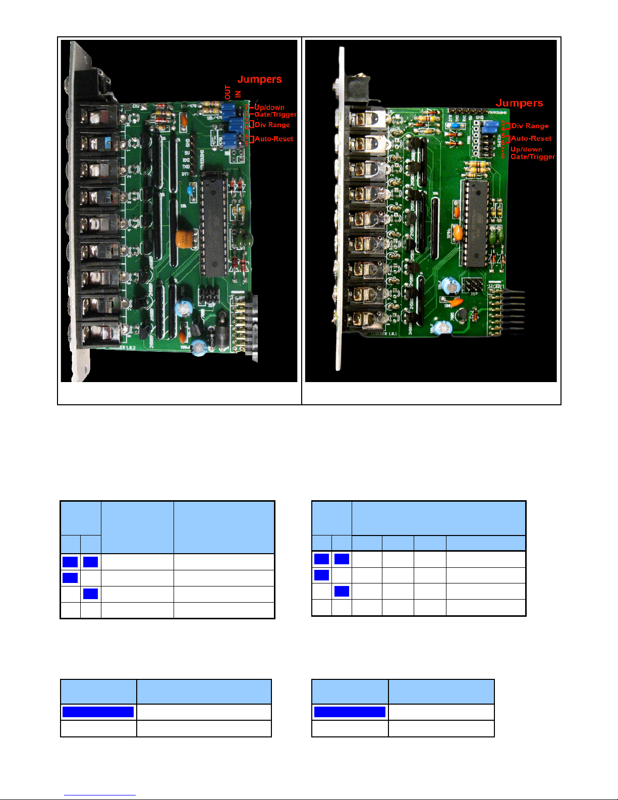
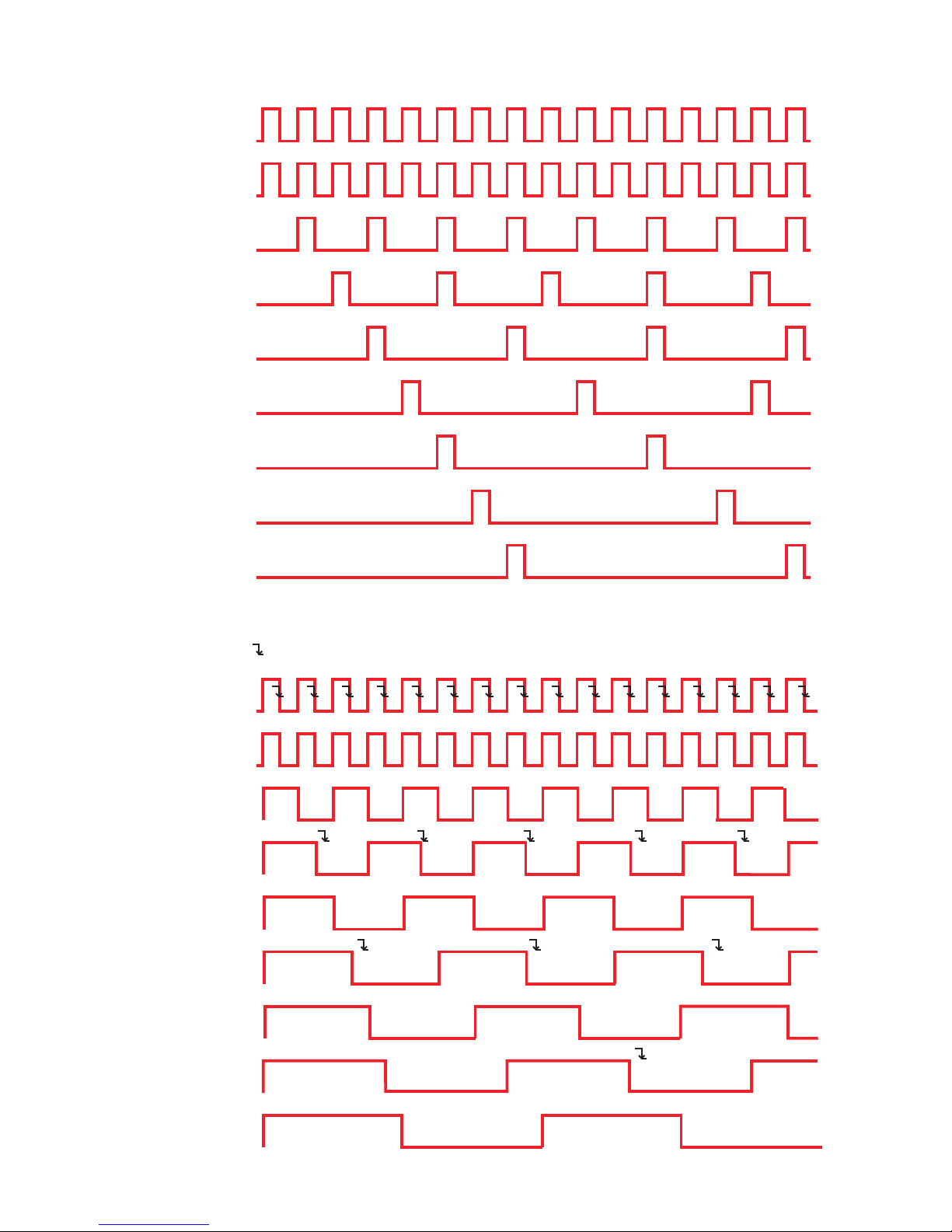
Up beat/Down beat jumper:
In Up-beat counting, each ack fires after "N" number of pulses are counted on the input ack (where N is the divide-by-
number). So, after a Reset pulse, only the /1 ack will fire on the first clock pulse. On the next clock pulse, the /1 and the /2
ack will fire, then on the next pulse the /1 and /3 acks will fire, etc... This is the default method for pcb v1.0 and v1.0.1,
unless it has been upgraded to v1.0.2 code.
In Down-counting, each ack fires when its count is 1. So all the acks will fire after a Reset pulse, and then count up to "N",
and fire again when they start over at 1. This is called" down-beat counting" because all the acks fire on the down-beat (first
clock pulse).
Gate/Trigger Mode jumper:
In Trigger mode, the acks output a pulse width equal to that of the input clock (the pulse width is not multiplied or divided
proportionally to the ack's divide-by amount). This is the default method for pcb v1.0 and v1.0.1, unless it has been upgraded
to v1.0.2 code.
In Gate mode, the width of the output pulses are 50% of the total wave. For example, the /6 ack will stay ON for 3 clock
pulses, and then turn OFF for 3 clock pulses. For even numbered divisions (/2, /4, /6, /8, etc) the transitions happen on the
input clock's rising edge.
Point of interest: In Gate mode, with odd-numbered divisions, the ack will turn ON on a rising edge of the input clock, and
then will turn OFF on a falling edge. For example, the /5 ack ought to stay on for 2.5 clock pulses, meaning it should go OFF
somewhere between the rising edge of clock pulses 2 and 3. Right in between these is the falling edge of pulse number 2, so
we can safely call it 2.5!
When in Gate mode (jumper 8), the difference between Up counting and down counting is simply that the gates are
inverted.
Auto Reset jumpers:
Jumpers 5 and 6 select the Auto-reset point, which causes the divide counters to reset after a certain number of clock pulses.
Note that divide-by amounts which are evenly divisable by the reset amount are not affected: e.g. with an auto-reset of 16,
divide-by outputs of 2, 4, 8, 16, etc are not changed.
Also, note that the CV Reset is independant of the Auto-reset. For example, Jack 7+R could be patched into the CV Reset
with umpers 3, 4, and 5 in. This would cause a reset every 7 clocks, plus an additional reset every 16 clocks.
There are too many combinations of Auto-reset and Max divide amounts to show all combinations!
Example: Auto-reset of 16 (Jumper 5 in, no Jumper 6), with Max Divide-by of 8 (Jumpers 3&4)
IN: 12345678910 11 12 13 14 15 16 17 18 19 20 21 22 23 24 25 26 27 28 29 30 31 32
3X X X X X X X X X X
5X X X X X X
7X X X X

Operation
Apply a clock signal to the Clock Input ack. Rising edges of 5V or greater will cause the internal dividing counters to be
incremented. Each ack has its own counter that counts from 1 to its divide-by-amount, and then resets back at 1. In up-beat
counting, each ack outputs a trigger pulse when its counter reaches the divide-by amount assigned to that ack. In down-
beat counting, each ack fires when its counter is 1. Typically, the outputs will patch to trigger-able or gate-able modules
(drum modules, ADSR envelope/transient generators, step sequencer clock input, etc..), but the RCD can also operate in the
audio frequency range, thus crudely stepping pitch downward.
Clock outputs (up-beat counting):
IN: 12345678910 11 12 13 14 15 16 17 18 19 20 21 22 23 24 25 26 27 28 29 30 31 32
1X X X X X X X X X X X X X X X X X X X X X X X X X X X X X X X X
2XXXXXXXXXXXXXXXX
3X X X X X X X X X X
4XXXXXXXX
5X X X X X X
6XXXXX
7X X X X
8X X X X
9X X X
10 XXX
11 X X
...
32 X
Clock outputs (down-beat counting):
IN: 12345678910 11 12 13 14 15 16 17 18 19 20 21 22 23 24 25 26 27 28 29 30 31 32
1X X X X X X X X X X X X X X X X X X X X X X X X X X X X X X X X
2XXXXXXXXXXXXXXXX
3X X X X X X X X X X X
4XXXXXXXX
5X X X X X X X
6XXXXXX
7X X X X X
8XXXX
CV Rotation
By applying a CV signal to the CV Rotate ack, the clock divisions will rotate throughout the output acks (see table 2). For
example, if you apply ust over 1.0V, Jack 1+R/Red will go from Divide-by-1 to Divide-by-2, and Jack 2+R/Orange will
become Divide-by-3... up to Jack 8+R/White which will wrap ("rotate") around to become Divide-by-1. Applying more CV to
the Rotate Jack will continue the rotation: next Jack 1 becomes Divide-by-3, then Divide-by-4, then Divide-by-5, until it's
Divide-by-8 at the maximum input CV. Some non-linearities exist in the CV response, especially in the upper extreme. See
diagram at end of this manual.
CV Reset
Applying a CV of 5V or greater to the CV Reset ack will cause all the divide counters to reset on the next clock pulse. So,
applying a reset pulse will not change the tempo, since the RCD will wait for the next clock pulse to actually do anything.
Counting will begin back at 1 after a Reset. A low/slow output on the RCD can be patched into Reset, or a second RCD
running on the same master clock can be set to run very slow and reset the first RCD after an arbitrary number of beats.

Rotation Tables
Table 2: Divide-by amounts at each jack, with max divide-by amount set to 8
(Jumper 3 in, Jumper 4 in):
Jacks
Voltage at CV Rotate Jack
<1.0V 1.00V - 1.65V 1.65V - 2.30V 2.30V - 2.95V 2.95V-3.60V 3.6V-4.30V 4.30V-5.10V >5.1V
1+R/Red 1 2 3 4 5 6 7 8
2+R/Orange 2 3 4 5 6 7 8 1
3+R/Yellow 3 4 5 6 7 8 1 2
4+R/Lt Green 4 5 6 7 8 1 2 3
5+R/Green 5 6 7 8 1 2 3 4
6+R/Blue 6 7 8 1 2 3 4 5
7+R/Violet 7 8 1 2 3 4 5 6
8+R/White 8 1 2 3 4 5 6 7
Table 3: Divide-by amounts at each jack, with max divide-by amount set to 16
(Jumper 3 in, no Jumper 4):
Jacks
Voltage at CV Rotate Jack
<
0.7V
0.7V -
1.0V
1.0V -
1.3V
1.3V -
1.7V
1.7V -
2.0V
2.0V -
2.3V
2.3V -
2.7V
2.7V -
3.0V
3.0V -
3.3V
3.3V -
3.7V
3.7V -
4.0V
4.0V -
4.3V
4.3V -
4.7V
4.7V -
5.1V
5.1V -
5.8V
>
5.8V
1+R/Red 9 10 11 12 13 14 15 16 1 2 3 4 5 6 7 8
2+R/Orange 10 11 12 13 14 15 16 1 2 3 4 5 6 7 8 9
3+R/Yellow 11 12 13 14 15 16 1 2 3 4 5 6 7 8 9 10
4+R/Lt Green 12 13 14 15 16 1 2 3 4 5 6 7 8 9 10 11
5+R/Green 13 14 15 16 1 2 3 4 5 6 7 8 9 10 11 12
6+R/Blue 14 15 16 1 2 3 4 5 6 7 8 9 10 11 12 13
7+R/Violet 15 16 1 2 3 4 5 6 7 8 9 10 11 12 13 14
8+R/White 16 1 2 3 4 5 6 7 8 9 10 11 12 13 14 15

Table 4: Divide-by amounts with max divide-by amount set to 32 (Jumper 3 out, Jumper 4 in):
Jacks
Voltage at CV Rotate Jack
<
0.5V
0.68V 0.86V 1.04V 1.22V 1.38V 1.54V 1.70V 1.86V 2.02V 2.18V 2.36V 2.52V 2.68V 2.82V 3.00V
1+R/Red 17 18 19 20 21 22 23 24 25 26 27 28 29 30 31 32
2+R/Orange 18 19 20 21 22 23 24 25 26 27 28 29 30 31 32 1
3+R/Yellow 19 20 21 22 23 24 25 26 27 28 29 30 31 32 1 2
4+R/Lt Green 20 21 22 23 24 25 26 27 28 29 30 31 32 1 2 3
5+R/Green 21 22 23 24 25 26 27 28 29 30 31 32 1 2 3 4
6+R/Blue 22 23 24 25 26 27 28 29 30 31 32 1 2 3 4 5
7+R/Violet 23 24 25 26 27 28 29 30 31 32 1 2 3 4 5 6
8+R/White 24 25 26 27 28 29 30 31 32 1 2 3 4 5 6 7
(con't) 3.18V 3.34V 3.50V 3.68V 3.82V 4.00V 4.18V 4.36V 4.54V 4.72V 4.94V 5.17V 5.43V 5.80V 6.52V >
6.52V
1+R/Red 16 17 18 19 20 21 22 23 24 25 26 27 28 29 30 31
2+R/Orange 17 18 19 20 21 22 23 24 25 26 27 28 29 30 31 32
3+R/Yellow 18 19 20 21 22 23 24 25 26 27 28 29 30 31 32 1
4+R/Lt Green 19 20 21 22 23 24 25 26 27 28 29 30 31 32 1 2
5+R/Green 20 21 22 23 24 25 26 27 28 29 30 31 32 1 2 3
6+R/Blue 21 22 23 24 25 26 27 28 29 30 31 32 1 2 3 4
7+R/Violet 22 23 24 25 26 27 28 29 30 31 32 1 2 3 4 5
8+R/White 23 24 25 26 27 28 29 30 31 32 1 2 3 4 5 6
Table 5: Divide-by amounts at each jack, with max divide-by amount set to 64 (no Jumper 3 or 4)
Jacks
Voltage at CV Rotate Jack
<
0.5V
0.68V 0.86V 1.04V 1.22V 1.38V 1.54V 1.70V 1.86V 2.02V 2.18V 2.36V 2.52V 2.68V 2.82V 3.00V
1+R/Red 33 34 35 36 37 38 39 40 41 42 43 44 45 46 47 48
2+R/Orange 34 35 36 37 38 39 40 41 42 43 44 45 46 47 48 49
3+R/Yellow 35 36 37 38 39 40 41 42 43 44 45 46 47 48 49 50
4+R/Lt Green 36 37 38 39 40 41 42 43 44 45 46 47 48 49 50 51
5+R/Green 37 38 39 40 41 42 43 44 45 46 47 48 49 50 51 52
6+R/Blue 38 39 40 41 42 43 44 45 46 47 48 49 50 51 52 53
7+R/Violet 39 40 41 42 43 44 45 46 47 48 49 50 51 52 53 54
8+R/White 40 41 42 43 44 45 46 47 48 49 50 51 52 53 54 55
(con't) 3.18V 3.34V 3.50V 3.68V 3.82V 4.00V 4.18V 4.36V 4.54V 4.72V 4.94V 5.17V 5.43V 5.80V 6.52V >
6.52V
1+R/Red 49 50 51 52 53 54 55 56 57 58 59 60 61 62 63 64
2+R/Orange 50 51 52 53 54 55 56 57 58 59 60 61 62 63 64 1
3+R/Yellow 51 52 53 54 55 56 57 58 59 60 61 62 63 64 1 2
4+R/Lt Green 52 53 54 55 56 57 58 59 60 61 62 63 64 1 2 3
5+R/Green 53 54 55 56 57 58 59 60 61 62 63 64 1 2 3 4
6+R/Blue 54 55 56 57 58 59 60 61 62 63 64 1 2 3 4 5
7+R/Violet 55 56 57 58 59 60 61 62 63 64 1 2 3 4 5 6
8+R/White 56 57 58 59 60 61 62 63 64 1 2 3 4 5 6 7

div by 1:
div by 5:
div by 6:
div by 7:
div by 8:
div by 4:
div by 3:
div by 2:
CLOCK INPUT:
123456789101112
6 12
13 14
7 14
15
5 10 15
3 6 9 12 15
16
1 2 3 4 5 6 7 8 9 10 11 12 13 14 15 16
8 16
4 8 12 16
2 4 6 8 10 12 14 16
div by 1:
div by 5:
div by 6:
div by 7:
div by 8:
div by 4:
div by 3:
div by 2:
CLOCK INPUT:
1 2 3 4 5 6 7 8 9 10 11 12 13 14 15 16
1 2 3 4 5 6 7 8 9 10 11 12 13 14 15 16
1 2 3 4 5 6 7 8 9 10 11 12 13 14 15 16
1 2 3 4 5 6 7 8 9 10 11 12 13 14 15 16
1 2 4 5 7 8 10 11 13 14 16
1 3 5 7 9 11 13 15
1 3 6 8 11 13 16
1 4 7 10 13 16
1 4 8 11 15
15913
TRIGGER MODE, UP-BEAT COUNTING (NO JUMPERS IN 7&8)
GATE MODE, DOWN-BEAT COUNTING (BOTH JUMPERS 7&8)
Indicates falling-edge of clock input (all others are rising-edge)
PCB or Code v1.0.2

in
Rotate Reset
0V - 5V
+5V
1+R
2+R
3+R
4+R
5+R
6+R
7+R
8+R
4ms Rotating Clock Divider
How CV Rotate Works
Example 1:
Example 2: Example 3:
More CV Rotate
Less CV Rotate
1+R
div by 1
div by 2
div by 3
div by 4
div by 5
div by 6
div by 7
div by 8
2+R
3+R
4+R
5+R
6+R
7+R
8+R
1+R
div by 1
div by 2
div by 3
div by 4
div by 5
div by 6
div by 7
div by 8
2+R
3+R
4+R
5+R
6+R
7+R
8+R
1+R
2+R
3+R
4+R
5+R
6+R
7+R
8+R
div by 7
div by 1
div by 2
div by 3
div by 4
div by 5
div by 6
div by 8
1+R
2+R
3+R
4+R
5+R
6+R
7+R
8+R
div by 1
div by 2
div by 3
div by 4
div by 5
div by 6
div by 7
div by 8
In this metaphorical illustration, applying a voltage to the Rotate jack makes the outer
circle of jacks rotate around the inner circle of divided clock signals. For a technical chart
of the exact voltages needed to cause exact rotations, see the User Manual.
1V applied to CV Rotate:
(Jacks shifted 1 unit clockwise)
1+R: div by 2
2+R: div by 3
3+R: div by 4
4+R: div by 5
5+R: div by 6
6+R: div by 7
7+R: div by 8
8+R: div by 1
2V applied to CV Rotate:
(Jacks shifted 2 units clockwise)
1+R: div by 3
2+R: div by 4
...
7+R: div by 1
8+R: div by 6
5.1V applied to CV Rotate:
(Jacks shifted 7 units clockwise)
1+R: div by 8
2+R: div by 1
...
7+R: div by 6
8+R: div by 7
This page assumes all jumpers are in their factory positions:i.e.only jumpers 3 and 4 are“in”
1V
2V
>5V
0V
Table of contents
Other 4ms Music Pedal manuals
Popular Music Pedal manuals by other brands

Mission
Mission VM-1 user guide

Noise Reap
Noise Reap Foundation user manual

Ritual Electronics
Ritual Electronics Miasma manual

Mountainking Electronics
Mountainking Electronics DECOMPOSER quick start guide

EarthQuaker Devices
EarthQuaker Devices Bellows Operation manual

flight of harmony
flight of harmony The Sound Of Shadows quick start guide