4RF Aprisa FE User manual
Aprisa FE Quick Start Guide 1.4.0 © 2017 4RF Limited. All rights reserved. This document is protected by copyright belonging to 4RF Limited and may
not be reproduced or republished in whole or part in any form without the prior written permission of 4RF Limited. While every precaution has been
taken in the preparation of this literature, 4RF Limited assumes no liability or errors and omissions, or from any damages resulting from use of this
information. The contents and any product specifications within it are subject to revision due to ongoing product improvements and may change
without notice. Aprisa and the 4RF logo are trademarks of 4RF Limited. All other marks are the property of their respective owners.
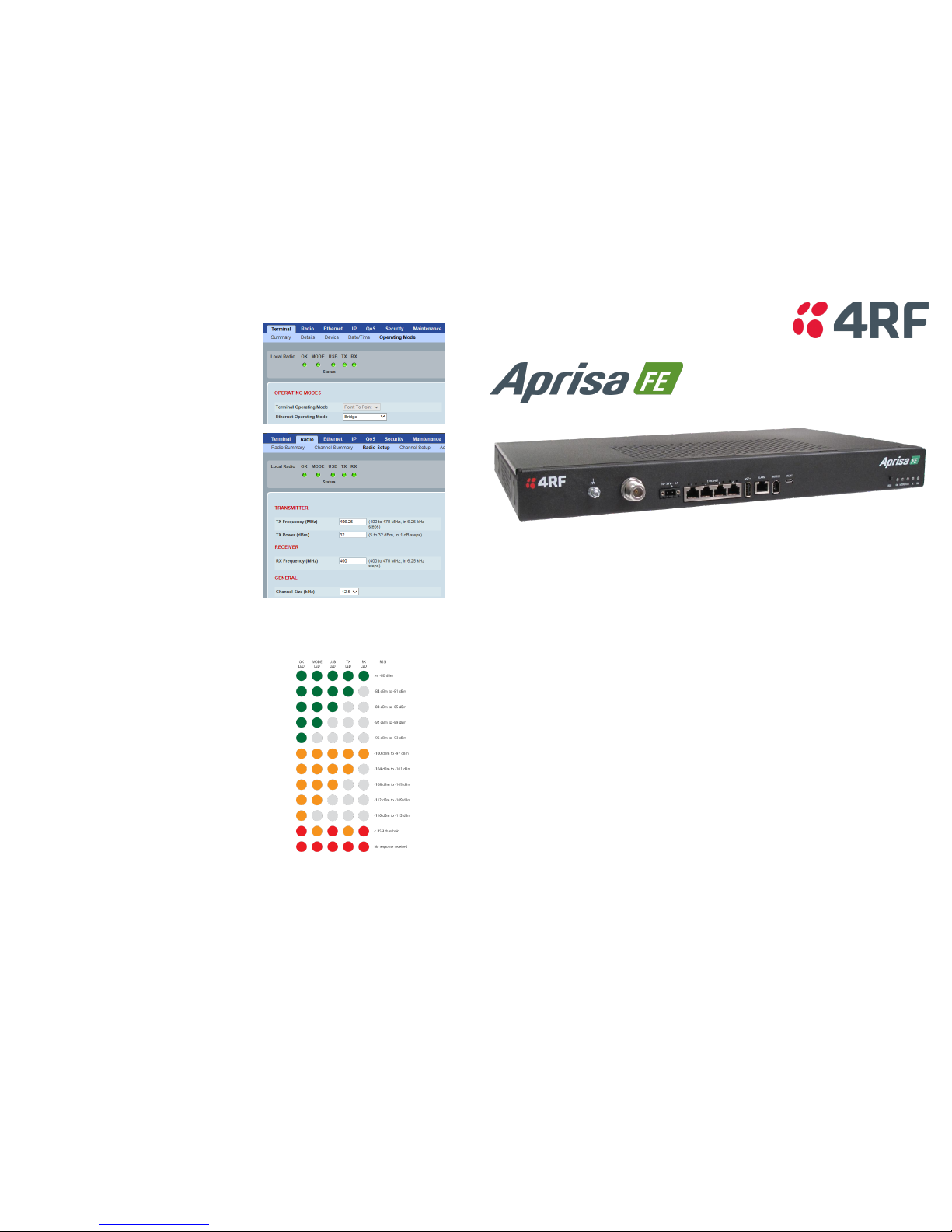
5. Setup the Aprisa FE radio
The Aprisa FE point-to-point radio end points are Local Radio and
Remote Radio.
Set the Ethernet Operating Mode required.
Set the Aprisa FE TX Frequency, RX Frequency, TX Power and Channel
Size to comply with your site license.
You can now configure the remaining terminal and link parameters and settings. Please refer to the Aprisa FE User Manual for detailed
instructions.
6. Monitor the Aprisa FE radio signal strength
When the link is installed, the radio signal strength can be monitored
on radios by setting the radio to Test Mode.
To enter Test Mode, press and hold the TEST button on the radio LED
panel until all the LEDs flash green (about 3 - 5 seconds).
In Test Mode, the LED Display panel presents a real time visual
display of the RSSI. This can be used to adjust the antenna for
optimum signal strength.
Note: The response time is variable and can be up to 5 seconds.
To exit Test Mode, press and hold the TEST button until all the LEDs
flash red (about 3 - 5seconds).
The OK, MODE and USB LEDs will be solid green and the TX and RX
LEDs will be solid or flash green if the link is operating correctly.
For more information, please refer to the Aprisa FE User Manual available from the 4RF website www.4rf.com/secure/ (login required).
Quick Start Guide
Aprisa FE Radio
Contents
Follow these steps to operate your Aprisa FE radio:
1. Check the box contents
2. Install the Aprisa FE radio and connect the protection earth
3. Connect the Antenna and apply power to the Aprisa FE radio
4. Connect to the Aprisa FE radio
5. Setup the Aprisa FE radio
6. Monitor the Aprisa FE radio signal strength

1. Check the box contents
The Aprisa FE is shipped to you in a box containing the following:
One Aprisa FE radio fitted with power connector.
The Aprisa FE has two chassis depth options:
300 mm depth (part number …30…)
440 mm depth (part number …44…)
Two mounting
brackets and 8
screws
Rack mounting
screws, washers
and nuts
DC power cable
3 m
USB Cable USB A to
USB micro B, 1 m
Ground cable 5 m
2. Install the Aprisa FE radio and connect the protection earth
The Aprisa FE is designed to be rack mounted in a standard 19” rack. The internal duplexer and external duplexer mounting are shown below:
The Aprisa FE has an M5 stud earth connection point on the left front of the enclosure to earth the
enclosure to a protection earth.
The antenna feeder cable should use grounding kits for lightning protection as specified or supplied
by the coaxial cable manufacturer to properly ground or bond the cable outer.
Note: The Aprisa FE radio operates within frequency bands that require a site license be issued by
the radio regulatory authority with jurisdiction over the territory in which the equipment is being
operated. It is the responsibility of the user, before operating the equipment, to ensure that
where required the appropriate license has been granted and all conditions attendant to that
license have been met.
Hereby, 4RF Limited declares that the Aprisa FE digital radio is in compliance with Directive
2014/53/EU. The full text of the EU declaration of conformity is available at the internet address
http://www.4rf.com/library/en.
3. Connect the antenna and apply power to the Aprisa FE radio
Connect the antenna to the antenna port N type female connector. If the antenna is not available, terminate the Antenna port with a N type
male 50 ohm terminator (10 Watts min).
The Aprisa FE is operated from a DC source of voltage between +10 VDC and +30 VDC (negative earth) and consumes
up to 35 Watts. External power supplies are available from 4RF as accessories (see the Aprisa FE User Manual).
The power connector (Molex 2 pin female) is supplied fitted to the radio. Wire your power source to the power
connector (- / +) and plug the connector into the radio. The connector screws should be fastened to secure the
connector.
Note: The radio fuses will blow if the connected power supply is over voltage or the polarity is reversed. Two spare
fuses are located inside the enclosure (see the ‘Spare Fuses’ section of the Aprisa FE User Manual).
Turn your power source on. The radio LEDs will flash orange for one second and then the OK, MODE, USB LEDs will light solid green and the TX
and RX LEDs will flash red.
When the radio has been configured and has registered with the other radio, the TX and RX LEDs will be solid or flash green if the link is
operating correctly.
The Aprisa FE radio is ready to operate.
Warning: On link operation, RF energy is radiated from the antenna. Do not stand in front of the antenna.
4. Connect to the Aprisa FE radio
The Aprisa FE has a factory default IP address of 169.254.50.10 with a subnet mask of 255.255.0.0.
Each radio in the Aprisa FE link must be setup with a unique IP address on the same subnet.
If the IP address of the radio is unknown, it can be changed via the Command Line Interface on the radio MGMT USB port:
Connect your PC USB port to the Aprisa FE MGMT USB port. USB to UART Bridge VCP Drivers are required to connect the radio USB
port to your PC. You can download and install the relevant driver from https://www.silabs.com/products/development-
tools/software/usb-to-uart-bridge-vcp-drivers.
Login to the radio with the default login ‘admin’ and password ‘admin’.
At the command prompt >> type ‘cd APRISASR-MIB-4RF’ and enter.
- type ‘set termEthController1IpAddress xxx.xxx.xxx.xxx’ and enter.
- type ‘set termEthController1SubnetMask 255.255.0.0’ and enter.
- type ‘set termEthController1Gateway xxx.xxx.xxx.xxx’ and enter.
If the IP address of the radio is known or is the default IP address, it can be changed via the Ethernet port:
Setup your PC for a compatible IP address e.g. 169.254.50.1 with a subnet mask of 255.255.0.0.
Connect your PC network port to one of the Aprisa FE Ethernet ports.
Open a browser and enter http://169.254.50.10.
Note: The Aprisa FE has a Self Signed security certificate which may cause the browser to prompt a certificate warning. It is safe to
ignore the warning and continue. The valid certificate is ‘Issued By: 4RF-APRISA’ which can be viewed in the browser.
Login to the radio with the default login ‘admin’ and password ‘admin’.
Change the IP address, Subnet mask and Gateway to network compatible IP addresses.
Table of contents
Other 4RF Network Hardware manuals

Popular Network Hardware manuals by other brands

Matrix Switch Corporation
Matrix Switch Corporation MSC-HD161DEL product manual

B&B Electronics
B&B Electronics ZXT9-IO-222R2 product manual

Yudor
Yudor YDS-16 user manual

D-Link
D-Link ShareCenter DNS-320L datasheet

Samsung
Samsung ES1642dc Hardware user manual

Honeywell Home
Honeywell Home LTEM-PV Installation and setup guide


