5D TACTICAL Router JigPro User manual

INSTRUCTIONS V1.2

508-834-4223 5DTACTICAL.COM
A
B
CDE
F G
H
J
I
K
L M
Q
P
O
N
PARTS & TOOLS
PARTS
1. Router
2. Drill
3. 5D Tactical ReadyMILL™
4. 3/8” Drill Bit
5. 21/64” Drill Bit
6. 5/32” Drill Bit
7. Vise
8. Shop Vac or Compressed Air
9. #2 Phillips Screwdriver
10. 7/64” Allen Wrench
11. Eye Protection
12. Ear Protection
13. WD-40 or Cutting Fluid
TOOLS NEEDED
A.... Guide Plate
B. .. Router Adapter
C. .. (4) Router Adapter
Screws
D... Router Adapter Side
Block
E.... (2) Router Side Block
Screws
F.... Left Side Plate
G... Right Side Plate
H... AR-15/AR-9 Buffer
Plate
I..... 308/AR-10 Buffer
Plate
J.... AR-15/AR-9
Takedown Adapter
K... .308/AR-10
Takedown Adapter
L.... AR-15/AR-9
Takedown Pin
M... .308/AR-10
Takedown Pin
N... Drill Guide
O... Buffer Adapter
P.... (14) Jig Screws
Q... Guide Pin Set

508-834-4223 5DTACTICAL.COM 3
PART 1: JIG ASSEMBLY
1-1 Clean surface of the 80% receiver
and apply masking tape to the sides.
1-2 Apply the Buffer Plate to the back
of the receiver as shown. Use grey
Buffer Plate for AR-15/AR-9 receivers and
black Buffer Plate for .308/AR-10 receivers.
1-3Loosely thread the Buffer Adapter
into the receiver until the Buffer
Plate is pressed against the back of the receiver.
1-4Loosely install the Takedown
Adapter to the Guide Plate using (2)
Jig Screws. Use grey Takedown Adapter for
AR-15/AR-9 receivers and black Takedown
Adapter for .308/AR-10 receivers.
1-5Align the receiver with the Takedown
Adapter, pass the Takedown Pin
through the receiver and adapter. Use the
correct Takedown Pin for the receiver.
1-6Align the Buffer Plate with the
holes in the rear of the Guide Plate.
Loosely install (2) Jig Screws.
ASSEMBLY
Thank you for your Router Jig Pro purchase. At 5D Tactical, we understand
you have chosen to spend your hard earned money with us, and because of that, we strive for 100%
customer satisfaction. Your Router Jig Pro carries a LIFETIME WARRANTY against manufacturer’s
defects. Please contact us by phone at 508-834-4223 or email sales@5DTactical.com with any
questions or concerns regarding the use of your Router Jig Pro. Replacement parts and a selec-
tion of 80% lowers are available for purchase on our website, 5DTactical.com.
AR-15/AR-9
.308/AR-10
.308/AR-10
AR-15/AR-9
AR-15/AR-9 .308/AR-10

508-834-4223 5DTACTICAL.COM
4
1-7While grasping Guide Plate, tighten
(4) Jig screws, securing Buffer Plate
and Takedown Adapter.
1-8Orient Side Plates, observing Left
and Right with at sides facing out.
Set Guide Plate and receiver assembly atop
Side Plates. Loosely thread (8) Jig Screws and
then tighten.
1-9While grasping Guide Plate, pass
Phillips screwdriver through
the hole in the Buffer Adapter, and tighten.
Periodically check for tightness during jig use.
1-10Install the Drill Guide as shown. Loosely
insert (2) Jig Screws, then tighten.
1-11
Clamp Jig Assembly securely in
a vise as shown by the notches
provided in the Side Plates. DO NOT
CLAMP JIG BY OUTSIDE OF SIDE
PLATES. DAMAGE WILL OCCUR.
REVIEW IMAGES CAREFULLY.
PART 2: DRILLING STEP 1
2-1Spray WD-40 into Drill Guide hole
and insert 21/64” drill bit. Do not
start the drill until the bit is fully inserted.
Using care to keep the drill bit straight and
perpendicular to the receiver, begin drilling.
Periodically pull the drill bit out of the Guide
to clear chips. Apply WD-40 liberally. Drill until
the bit exits the bottom of the receiver.

508-834-4223 5DTACTICAL.COM 5
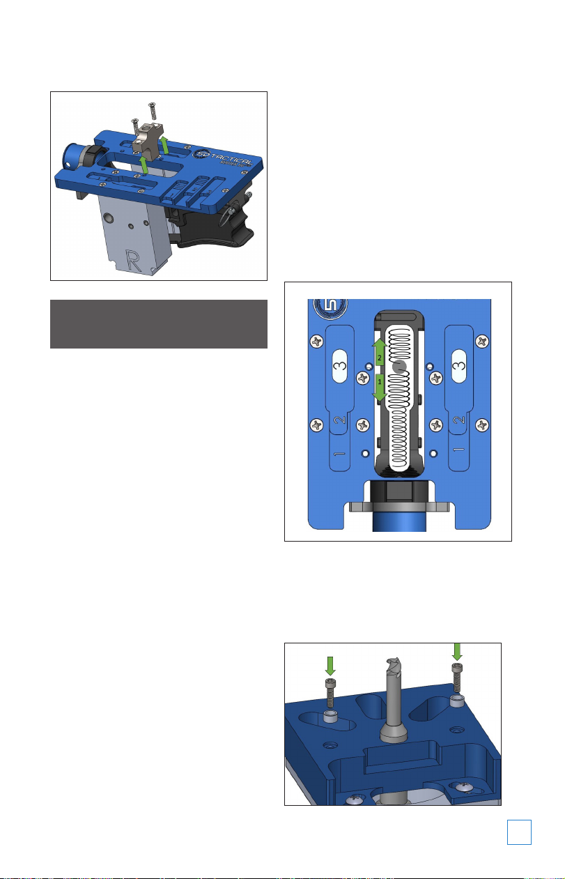
2-2Uninstall the Drill Guide by
removing the (2) Jig Screws.
PART 3: MILLING STEP 1
GO TO APPENDIX A FOR ROUTER ADAPTER
INSTALLATION INSTRUCTIONS
GENERAL NOTES ON MILLING -
READ ENTIRELY:
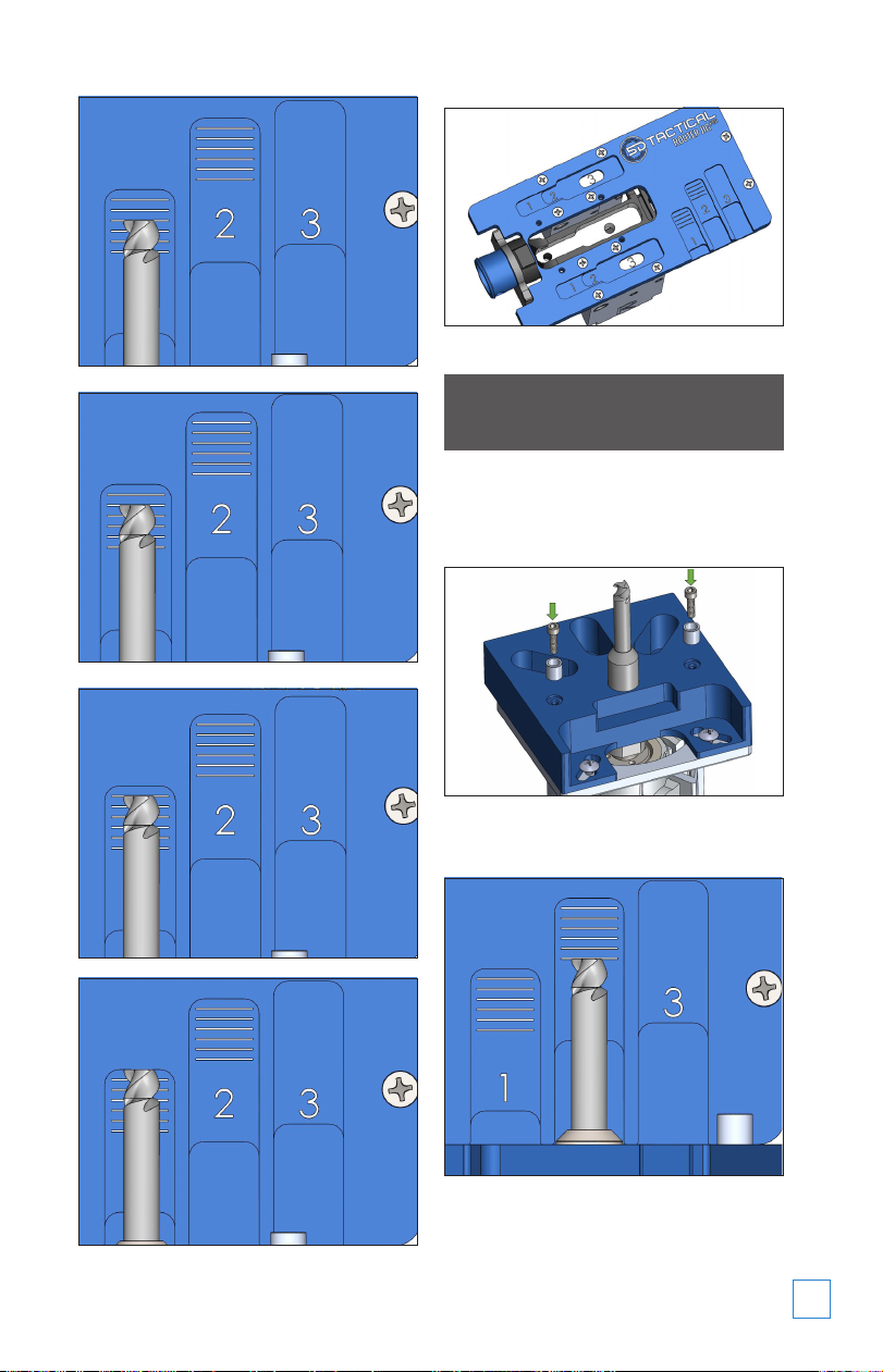
• The provided depth gauge hash marks
denote the maximum depth of cut per
pass. BEGINNERS AND THOSE SEEKING
MAXIMUM FINISH QUALITY SHOULD
MAKE MILLING PASSES AT LESS THAN
A FULL HASH MARK. Attempting to mill
to at depth increments higher than
recommended can cause damage to the
end mill and/or receiver.
• Ensure that your router base lock is
tight and functioning properly. If the
router depth moves while milling,
the end mill and/or receiver can be
damaged.
• If using a variable speed router, set to
the highest speed setting. Do not insert
or remove the end mill while the router is
spinning.
• Prior to turning the router on, ENSURE
THE END MILL IS CENTERED WITHIN THE
MILLING PILOT HOLE AND NOT CONTACTING
ANY PART OF THE RECEIVER.Hold rmly
and apply moderate downward pressure
when starting the router.
• While milling, move the router smoothly
and in a clockwise manner as shown in
the image. Keep the Router Adapter at
against the Guide Plate at all times. Avoid
abruptly pulling the router or exerting
excessive force. Slowly nibble away at
the receiver. If you begin to experience
chattering, slow down and/or take
shallower depths of cut. Apply WD-40 or
cutting uid liberally and remove chips
frequently.
3-1Install #1 (Short) Guide Pins to
Router Adapter using (2) Guide Pin
Screws and 7/64” Allen Wrench. Open end of
pins should be facing up. Do not overtighten.
Make sure pins are fully seated.

508-834-4223 5DTACTICAL.COM
6
3-2Set end mill depth to the rst hash
mark using Depth Gauge #1. Set
depth by holding the base of Router Adapter
against the edge of the Guide Plate. Be sure
Guide Pins are not between the Adapter
and Guide Plate. Make sure router depth
adjustment is locked after each depth setting.
3-3Orient Jig so the buffer extension
is closest to the user. Place router
on Guide Plate, with the end mill centered
within the drill hole. The Guide Pins should be
positioned inside the #1 Guide Cavities on both
sides. Hold rmly, turn router on and mill using
consistent pressure and speed, moving in a
clockwise manner.
3-4Complete the rst pass of milling,
allowing the Guide Pins to trace
the entire area of the Guide Cavities.
3-5Set end mill depth to the second
hash mark. Mill second pass
following the same method and process as
outlined in steps 3-3 and 3-4.
3-6Continue milling in this manner,
adjusting end mill depth 1 hash
mark per pass until you have milled to the
bottom of Depth Gauge #1. STOP Before
continuing to Depth Gauge #2, the #2
(Medium) Guide Pins must be installed.

508-834-4223 5DTACTICAL.COM 7
PART 4: MILLING STEP 2
4-1Remove #1 (Short) Guide Pins and
install #2 (Medium) Guide Pins. Do
not overtighten.
4-2Set end mill depth to the rst hash
mark using Depth Gauge #2.

508-834-4223 5DTACTICAL.COM
8
4-3Complete the rst milling pass
allowing the Guide Pins to follow
the #2 Guide Cavities.
4-4Set end mill depth to the second
hash mark. Mill the second pass
following the same method and process.
4-5Continue milling, adjusting depth
by 1 hash mark until you have
milled to the bottom of Depth Gauge #2. STOP
Before continuing to Depth Gauge #3, the #3
(Long) Guide Pins must be installed.

508-834-4223 5DTACTICAL.COM 9
PART 5: MILLING STEP 3
5-1Remove #2 (Medium) Guide Pins
and install #3 (Long) Guide Pins.
Do not overtighten.
5-2Set end mill depth to bottom of
Depth Gauge #3.
5-3Place router on Guide Plate, with
the end mill centered within the drill
hole. The Guide Pins should be positioned inside
the #3 Guide Holes on both sides. Gently mill in a
clockwise manner until the trigger slot is formed.
SECTION 6: FINAL DRILLING
6-1Clamp Jig Assembly in the Vise by
the edges of the side plates, with
the RIGHT Side Plate facing up. Ensure that the
assembly is level. Spray WD-40 into the large
Guide Hole and insert 3/8” drill bit. Do not start
drill until bit is fully inserted in the Guide Hole.
Apply moderate pressure and drill until the bit
penetrates the right side wall and continue
drilling through left side wall.
6-2Spray WD-40 into both small Guide
Holes and insert 5/32” drill bit
into either remaining Guide Hole. Do not start
drill until bit is fully inserted. Apply moderate
pressure and drill until the bit penetrates the
right side wall and continue drilling through
left side wall. Repeat for remaining small
Guide Hole.

508-834-4223 5DTACTICAL.COM
10
NOTE: If your drill bits are not long enough
to penetrate both walls, ip jig over and
repeat process. Receivers with spray-on
coatings such as Cerakote and Duracoat
should be drilled from both sides for maximum
nish quality.
PART 7: DISASSEMBLY
7-1Remove Buffer Adapter. Loosen or
completely remove Buffer Plate.
Remove Takedown Pin. The Finished receiver
can now be removed from the jig.
FINAL PRODUCT
APPENDIX A –
ROUTER ADAPTER INSTALLATION
NOTE: Your ReadyMILL™ is custom
designed to t tightly inside the Router
Adapter Bearing. Prior to rst use, the tool
holder portion of the ReadyMILL™ may
require light oiling and/or cleaning with a
mildly abrasive scouring pad to ensure a
reliable slip-t. DO NOT SAND OR GRIND
YOUR ReadyMILL™. Do not force the
ReadyMILL™ into the bearing, or it may
become stuck.
The end mill cutting teeth are extremely
sharp, use the protective end mill cap
whenever handling the ReadyMILL™.
Remember to remove the end mill cap
prior to use. Use caution when removing
the end mill cap and wear gloves. Drilling
and cutting tools can shatter, remember to
always wear eye protection while operating
power tools.
Reference the chart on the next page for
specic instructions on how to install the
Router Adapter to your router model.

508-834-4223 5DTACTICAL.COM 11
ROUTER INSTALL READYMILL
MODEL METHOD MODEL
Bosch PR10EX............. 2..................A
Bosch PR20EVX........... 2..................A
Bosch 1617EV ............ 3*.................D
Bosch 1617EVS .......... 3*.................D
Craftsman 28212Y....... 1 ..................B
Craftsman 2767.......... 3*.................D
Craftsman 27683........ 3*.................D
Craftsman 50429........ 3*.................D
DeWalt DWE6000 ....... 2..................A
DeWalt DWP611Z........ 1..................B
DeWalt DW616 ........... 3*.................D
DeWalt DW618 ........... 3*.................D
Hitachi M12VC............ 3*.................D
Makita RT0701C......... 2..................C
Porter Cable 450......... 1..................B
Porter Cable 6430....... 2..................A
Porter Cable 6435....... 2..................A
Rigid R24012X............. 2..................A
* Installation Method 3 Requires Full-Size Router
Adapter Plate
X - Pull out router base to attain minimum depth
Y - Requires only 3 Router Adapter Screws
Z - #1 Recommended Router
A1-1
Before proceeding, check that
your router depth lock is fully
functional. If necessary, tighten router depth
lock. On most models, a nut or setscrew can
be tightened to adjust the tension of the depth
lock. If your router depth moves while milling,
damage to the receiver and/or end mill may
occur.
A1-2
Prepare your router for milling
by installing the ReadyMILL™.
Unplug your router. Remove the plastic
baseplate from the router base, and separate
the base from the router. Remove the collet.
Thread on the ReadyMILL™ and tighten using
a wrench. Reinstall the router base.
A1-3
Orient the Router Adapter with
the bearing facing toward the
router, and the notch away from the power
cord. Pass the large diameter portion of the
ReadyMILL™ through the bearing to center
the Router Adapter with the Router.
A1-4
Installation Method 1. With the
Adapter at against router base,
align Router Adapter with 4 screw holes in
router base, loosely install (4) Router Adapter
Screws, then tighten.
A1-5
Installation Method 2. Align
Router Adapter with 2 screw
holes in front of router base, and loosely
install (2) Router Adapter Screws. Loosely
install Router Adapter Side Block to accessory
attachment hole on back of router with (1)
Router Side Block Screw. Use the appropriate
size for your router. Loosely install (1) Router
Adapter Screw into the Side Block through
the Router Adapter. Tighten (2) front Router
Adapter Screws. Press Side Block against
router and tighten (1) Router Side Block Screw.

508-834-4223 5DTACTICAL.COM
12
508-834-4223 5DTACTICAL.COM
Other manuals for Router JigPro
1
Table of contents
Other 5D TACTICAL Tools manuals