6TL YAV904X8 User manual

Two pole 4x8 Switching Matrix
YAV904X8
620020E05
Created 13/02/07
Updated 01/12/15

TECHNICAL MANUAL 620020E05
Due to the continuous products improvement, the indications of the present manual can be modified without previous warning and in any
case are a contract commitment. The present information publishing does not represent resignation of intellectual property or patent.
Copyright 2009-2010 S.A. Sistel -E 08211 BARCELONA Pag. 2
This manual is related to the following product:
Product –P/N
YAV904X8
Hardware version
02
Software version
01
Issued date
29/06/2010
Document History
Version
Issued date
Reason
E1
02/2007
Preliminar version
E2
03/2010
Revision to add new PHI6 panels
E3
05/2010
C language example added
E4
06/2010
Change spec. Max current 1A
E05
5/03/2012
Included board test procedures and packaging
Versions History
Version
Issued date
Reason
V01.01
02/2007
First Release
V02.01
03/2007
Minor changes

TECHNICAL MANUAL 620020E05
Due to the continuous products improvement, the indications of the present manual can be modified without previous warning and in any
case are a contract commitment. The present information publishing does not represent resignation of intellectual property or patent.
Copyright 2009-2010 S.A. Sistel -E 08211 BARCELONA Pag. 3
TABLE OF CONTENTS
0. Before you begin ............................................................................................................4
1. Safety...............................................................................................................................4
1.1 Symbols and safety terms .........................................................................................4
1.2 Precautions against damage to people .....................................................................5
1.3 Precautions against damage to the product ..............................................................5
2. Limits of the guarantee..................................................................................................5
3. Description and main features ......................................................................................6
3.1 General features........................................................................................................6
3.2 Typical applications with YAV904X8 .........................................................................6
3.3 Ordering information..................................................................................................7
3.4 Device electrical Characteristics................................................................................7
3.5 Block diagram............................................................................................................8
3.6 Connectors & Jumpers..............................................................................................8
3.6.1 X1 Connector (Device Power & CAN)................................................................8
3.6.2 Jumpers..............................................................................................................8
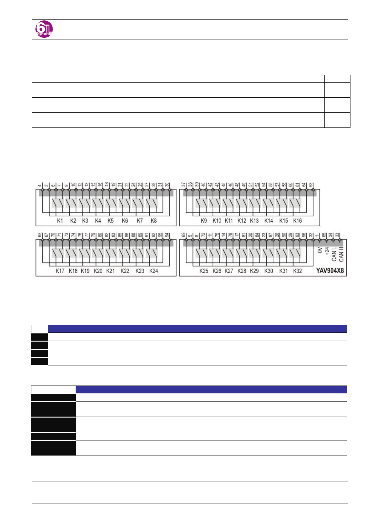
3.6.3 X2 Connector (Relays).......................................................................................9
3.6.4 LEDs ..................................................................................................................9
3.7 YAV904X8 Dimensions...........................................................................................10
4. Low level CAN commands...........................................................................................11
4.1 Example: Managing a YAV board using C language...............................................11
5. PHI6-Explorer panel......................................................................................................14
6. Install/Uninstall YAV modules into/from a VPC Receiver .........................................16
6.1 Receiver connector..................................................................................................16
6.1.1 YAVs with 96 pin connector..............................................................................16
6.2 Connections.............................................................................................................17
6.2.1 Connecting cables into YAV module terminals.................................................17
7. Getting started with your YAV module.......................................................................18
7.1 CAN Interface..........................................................................................................18
7.2 CAN bus wiring........................................................................................................18
7.3 PHI6-EXPLORER....................................................................................................18
8. YAV modules overview ................................................................................................19
8.1 YAV modules common information .........................................................................19
8.1.1 SW1 DIP switch functionality............................................................................19
8.1.2 CAN bus communication speed.......................................................................19
8.1.3 YAV module address........................................................................................20
8.2 YAV modules standard addressing & Virginia Panel Receivers..............................20
9. Certifications.................................................................................................................24
10. Test................................................................................................................................25

TECHNICAL MANUAL 620020E05
Due to the continuous products improvement, the indications of the present manual can be modified without previous warning and in any
case are a contract commitment. The present information publishing does not represent resignation of intellectual property or patent.
Copyright 2009-2010 S.A. Sistel -E 08211 BARCELONA Pag. 4
0.Before you begin
Thank you very much for purchasing this product.
This manual contains the information of the characteristics, performance and usage of the system/module
required for using it.
When using the system, observe the following:
Read this manual carefully to understand the contents well, and make the proper use of this system
accordingly.
Keep the manual safely for ready reference at any time. For basic operation of the system/module, also
read the relevant manuals carefully to understand the contents well, and then make the proper use of
this system accordingly.
1.Safety
Follow the following safety measures to avoid and prevent damaging this product, products connected to it, or
people.
Only qualified and entitled1personnel are authorized to carry out operations of installation and routine on the
devices described in this manual. The company installing it would bear responsibility for any security or
operating failure, when such failure is due to the parameters incorrect programming.
The product described in this manual can be configured to comply with the ruling of different countries. The
manufacturer does not hold any responsibility if the company installing it does not configured it according to the
legal, commercial or security prescriptions that may be in force in the place of installation or otherwise agreed
with the customer.
Should you need to access other components of the system while you are using this product, as a measure of
precaution, read the General Safety Summary in the other products technical manuals
1.1 Symbols and safety terms
The following symbols may appear on the product or its documentation
1The qualified staff must have proved their technical knowledge of this product and should have the corresponding accreditation.
DANGER
High Voltage
Earth protection
WARNING
See manual

TECHNICAL MANUAL 620020E05
Due to the continuous products improvement, the indications of the present manual can be modified without previous warning and in any
case are a contract commitment. The present information publishing does not represent resignation of intellectual property or patent.
Copyright 2009-2010 S.A. Sistel -E 08211 BARCELONA Pag. 5
1.2 Precautions against damage to people
Do not work on the product with the
power on.
To avoid electrical discharge, this product must not be handled with
the system powered on and in any case it may not be operated
without protective covers.
1.3 Precautions against damage to the product
Do not insert / unplug cards or other
electronic elements when powered up
The connection/disconnection of the I/O’s when plugged to the
power could produce a sequence of connections that could damage
electronic components which had been previously connected to their
corresponding reference earth.
Do not force the connection tag strips
The connection tag strips are connected exerting a small pressure. If
you encounter difficulty to plug them this may mean that they are
upside down or not aligned. If they are forced, besides the damage
to the strip you can cause damages on the electronics.
Secure the ground connections quality.
All the ground connections must be star-type and with the suitable
section. Loop ground connections are potential receptor antennas
with capacity to generate important current peaks.
Use suitable packing material for
transportation
An electronic module with a lot of fragile components should be
transported with a good protection packaging. A collision can cause
damages that could appear long time after the start up.
Do not install this product near heat
sources, strong vibrations or high
humidity that exceeds the technical
specifications.
Check that the product works without vibrations that exceed the
maximum levels specified, and which could damage its integrity or
cause a contact to become disconnected. The product should work
without humidity and in the temperature range detailed in the
technical specifications.
2.Limits of the guarantee
Products are supplied to the latest available development state at the time of manufacture. Should there
be any future changes for functional or productive improvements of the products; the manufacturer does
not hold any obligation to reprocess at no charge the products that have been already manufactured to
upgrade them to the latest versions.
All the products supplied by S.A. Sistel have passed all established quality controls as well as the EMC
(Electromagnetic Compatibility Checks). The manufacturer cannot be held responsible for any damage
produced by defective manipulation, installation or incompatibility with other products.
The products’ guarantee will only be in force when the installation has been done in accordance with
the technical prescriptions in this manual and the settled general standards: Low Voltage Electro Tech-
nical Regulation (or equivalent for each country) and CE regulations for the Electromagnetic Compatibil-
ity.

TECHNICAL MANUAL 620020E05
Due to the continuous products improvement, the indications of the present manual can be modified without previous warning and in any
case are a contract commitment. The present information publishing does not represent resignation of intellectual property or patent.
Copyright 2009-2010 S.A. Sistel -E 08211 BARCELONA Pag. 6
3.Description and main features
The multiplexer YAV904X8 is designed for the isolated switching of DMM signals. Its four
branches are featuring 8 double relays each. By joining the common pins of each branch, a
32 relays multiplexer can be set.
In the case the system requires high precission measurements, a two branch matrix can be
configured, allowing 4-wire measurements (resistors), voltage measurements by using
guards or bridges excitation while measuring (the case of load cells).
The board is organized in 4 groups of 8 bipolar relays, with double contact acces to each
branch, therefore, we have the possibility to set up different multiplexer configurations,
depending on the connections we make inside the test fixture:
Set up
Connections inside the fixture
1x 32 relays multiplexer
Join pin 30 to pin 36
Join pin 31 to pin 37
Join pin 63 to pin 67
Join pin 64 to pin 68
Join pin 94 to pin 5
Join pin 95 to pin 69
2x 16 relays multiplexer
Join pin 30 to pin 36
Join pin 31 to pin 37
Join pin 94 to pin 5
Join pin 95 to pin 69
Four times 1x 8 multiplexer
Don’t join anything
Two times 1x 8 + 1x 16 multiplexer
Join pin 94 to pin 5
Join pin 95 to pin 69
1x8 + 1x 24 multiplexers
Join pin 63 to pin 67
Join pin 64 to pin 68
Join pin 94 to pin 5
Join pin 95 to pin 69
3.1 General features
32 DPST relays up to 60V 1A
Configurable as matrix or scanner mode
Lab View drivers available
3.2 Typical applications with YAV904X8
Two or four wires measuring instruments switching
2 wire floating loads selection

TECHNICAL MANUAL 620020E05
Due to the continuous products improvement, the indications of the present manual can be modified without previous warning and in any
case are a contract commitment. The present information publishing does not represent resignation of intellectual property or patent.
Copyright 2009-2010 S.A. Sistel -E 08211 BARCELONA Pag. 7
3.3 Ordering information
Descripción
P/N
Two pole 4x8 Switching Matrix
YAV904X8
3.4 Device electrical Characteristics
Parameter
At Te= 5 … 65ºC, unless otherwise specified
Symbol
Values
Unit
Min.
Typ.
Max.
Operating Parameters
Operating voltage
Vbb
18
-
30
VDC
Operating current (At @24VDC)
IGND
40
-
390
mA
Thermal Ratings
Ambient operating temperature
TA
5
-
65
ºC
Power Dissipation (TA= 25 ºC)
PD
1
-
10
W
Module Switching specifications
Rated current (Cos ø =1) @ 60VAC
IN
-
-
1
A
Maximum switching voltage DC/AC @ 0,5A
VM DC/AC
-
-
150
V
Due to YAV904X8 overall design, the current limitation is up to 1A. Therefore, the following
chart must be considered with the ‘Rated operating current’ up to 1A. At this current level,
maximum switching voltage is 60V.

TECHNICAL MANUAL 620020E05
Due to the continuous products improvement, the indications of the present manual can be modified without previous warning and in any
case are a contract commitment. The present information publishing does not represent resignation of intellectual property or patent.
Copyright 2009-2010 S.A. Sistel -E 08211 BARCELONA Pag. 8
Relay Contact specifications
Maximum switching power
-
62,5
-
VA
Mechanical endurance
-
15x106
-
Cycles
Electrical endurance
-
>100000
-
Cycles
Maximum electrical operation frequency
-
1800
Cycles/h
Contact resistance
-
<50
-
mOhm
Operate time
TON
-
7
-
ms
Release time
TOFF
-
3
-
ms
3.5 Block diagram
3.6 Connectors & Jumpers
3.6.1 X1 Connector (Device Power & CAN)
Pin
Description
1
GND
2
+24V
3
CAN Low
4
CAN High
3.6.2 Jumpers
Jumper
Description
SW1: Address
CAN bus speed and the device address in the network can be set.
SW2: UPLOAD
FACTORY USE; Must be OPEN when normal operation. With the jumper set, we can enable the YAV board for
firmware downloading through serial port
SW3: ALT
FACTORY USE; Must be CLOSED when normal operation. With the jumper set, we can enable the YAV board
for firmware downloading through CAN bus
SW4: RESET
FACTORY USE; Must be OPEN when normal operation. Temporary bridge here, causes a reset of the board.
SW4: CANEND
When the device is network end, 120 Ohm resistor is mandatory. Bridging SW4, will place 120 Ohm resistor
between CAN_High and CAN_Low.

TECHNICAL MANUAL 620020E05
Due to the continuous products improvement, the indications of the present manual can be modified without previous warning and in any
case are a contract commitment. The present information publishing does not represent resignation of intellectual property or patent.
Copyright 2009-2010 S.A. Sistel -E 08211 BARCELONA Pag. 9
3.6.3 X2 Connector (Relays)
Module function
Receiver Pos. #
YAV904X8: 4 Rows x 8 Colums 2 ways relay matrix
I.T.A. Module P/N
510 108 126
I.T.A. contact P/N
610 110 108
I.T.A. Patchcord
720 102 101
Pin
Description
Pin
Description
Pin
Description
1
0V
33
CAN L
65
+24V
2
Position ID Bit 0
34
CAN H
66
Position ID Bit 2
3
Row A Common +
35
Position ID Bit 1
67
Row C Common +
4
Row A Common -
36
Row B Common +
68
Row C Common -
5
Row D Common +
37
Row B Common -
69
Row D Common -
6
Row A Bit P0L/0 +
38
70
Row C Bit P1L/0 +
7
Row A Bit P0L/0 -
39
Row B Bit P0H/0 +
71
Row C Bit P1L/0 -
8
Row D Bit P1H/0 +
40
Row B Bit P0H/0 -
72
Row D Bit P1H/0 -
9
Row A Bit P0L/1 +
41
73
Row C Bit P1L/1 +
10
Row A Bit P0L/1 -
42
Row B Bit P0H/1 +
74
Row C Bit P1L/1 -
11
Row D Bit P1H/1 +
43
Row B Bit P0H/1 -
75
Row D Bit P1H/1 -
12
Row A Bit P0L/2 +
44
76
Row C Bit P1L/2 +
13
Row A Bit P0L/2 -
45
Row B Bit P0H/2 +
77
Row C Bit P1L/2 -
14
Row D Bit P1H/2 +
46
Row B Bit P0H/2 -
78
Row D Bit P1H/2 -
15
Row A Bit P0L/3 +
47
79
Row C Bit P1L/3 +
16
Row A Bit P0L/3 -
48
Row B Bit P0H/3 +
80
Row C Bit P1L/3 -
17
Row D Bit P1H/3 +
49
Row B Bit P0H/3 -
81
Row D Bit P1H/3 -
18
Row A Bit P0L/4 +
50
82
Row C Bit P1L/4 +
19
Row A Bit P0L/4 -
51
Row B Bit P0H/4 +
83
Row C Bit P1L/4 -
20
Row D Bit P1H/4 +
52
Row B Bit P0H/4 -
84
Row D Bit P1H/4 -
21
Row A Bit P0L/5 +
53
85
Row C Bit P1L/5 +
22
Row A Bit P0L/5 -
54
Row B Bit P0H/5 +
86
Row C Bit P1L/5 -
23
Row D Bit P1H/5 +
55
Row B Bit P0H/5 -
87
Row D Bit P1H/5 -
24
Row A Bit P0L/6 +
56
88
Row C Bit P1L/6 +
25
Row A Bit P0L/6 -
57
Row B Bit P0H/6 +
89
Row C Bit P1L/6 -
26
Row D Bit P1H/6 +
58
Row B Bit P0H/6 -
90
Row D Bit P1H/6 -
27
Row A Bit P0L/7 +
59
91
Row C Bit P1L/7 +
28
Row A Bit P0L/7 -
60
Row B Bit P0H/7 +
92
Row C Bit P1L/7 -
29
Row D Bit P1H/7 +
61
Row B Bit P0H/7 -
93
Row D Bit P1H/7 -
30
Row A Common +
62
94
Row C Common +
31
Row A Common -
63
Row B Common +
95
Row C Common -
32
Row D Common +
64
Row B Common -
96
Row D Common -
3.6.4 LEDs
Led
Description
STATUS
This led will bright if the module has firmware loaded and is powered on. If the module is powered on but no
firmware is running, led will not bright.

TECHNICAL MANUAL 620020E05
Due to the continuous products improvement, the indications of the present manual can be modified without previous warning and in any
case are a contract commitment. The present information publishing does not represent resignation of intellectual property or patent.
Copyright 2009-2010 S.A. Sistel -E 08211 BARCELONA Pag. 10
3.7 YAV904X8 Dimensions
YAV boards for factors are showed below.
YAV904X8 is Form A.

TECHNICAL MANUAL 620020E05
Due to the continuous products improvement, the indications of the present manual can be modified without previous warning and in any
case are a contract commitment. The present information publishing does not represent resignation of intellectual property or patent.
Copyright 2009-2010 S.A. Sistel -E 08211 BARCELONA Pag. 11
4.Low level CAN commands
Following, details on all CAN messages available to manage the YAV904X8 module
YAV904x8
Action Dir Ident Length Byte 0 Byte 1 Byte 2 Byte 3 Byte 4 Byte 5 Byte 6 Byte 7
Set OFF One Relay Rx 0x155102xx 4 0x02 0x01 Relay 0x00
Set ON One Relay Rx 0x155102xx 4 0x02 0x01 Relay 0x01
TOGGLE One Relay Rx 0x155102xx 4 0x02 0x01 Relay 0x02
BLINK One Relay Rx 0x155102xx 4 0x02 0x01 Relay 0x03
PULSE ON One Relay Rx 0x155102xx 5 0x02 0x01 Relay 0x04 Time (10ms)
PULSE OFF One Relay Rx 0x155102xx 5 0x02 0x01 Relay 0x05 Time (10ms)
ASK One Relay Rx 0x155102xx 3 0x02 0x02 Relay
One Relay Status Tx 0x155202xx 4 0x02 0x02 Relay Status
Set OFF Several Relays Rx 0x155102xx 7 0x02 0x03 Relays 0 Relays 1 Relays 2 Relays 3 0x00
Set ON Several Relays Rx 0x155102xx 7 0x02 0x03 Relays 0 Relays 1 Relays 2 Relays 3 0x01
TOGGLE Several Relays Rx 0x155102xx 7 0x02 0x03 Relays 0 Relays 1 Relays 2 Relays 3 0x02
BLINK Several Relays Rx 0x155102xx 7 0x02 0x03 Relays 0 Relays 1 Relays 2 Relays 3 0x03
PULSE ON Several Relays Rx 0x155102xx 8 0x02 0x03 Relays 0 Relays 1 Relays 2 Relays 3 0x04 Time (10ms)
PULSE OFF Several Relays Rx 0x155102xx 8 0x02 0x03 Relays 0 Relays 1 Relays 2 Relays 3 0x05 Time (10ms)
Set OUT All Relays Rx 0x155102xx 7 0x02 0x03 Relays 0 Relays 1 Relays 2 Relays 3 0x06
ASK ALL Relays Rx 0x155102xx 3 0x02 0x04 Autosend
All Relays Status Tx 0x155202xx 6 0x02 0x04 Relays 0 Relays 1 Relays 2 Relays 3
Action Dir Ident Length Byte 0 Byte 1 Byte 2 Byte 3 Byte 4 Byte 5 Byte 6 Byte 7
Read I2C Data Word 24LC256 Rx 0x155102xx 5 0x02 0xFA 0xF1 ADD LOW ADD HIGH
Write I2C Data Word 24LC256 Rx 0x155102xx 7 0x02 0xFA 0xF2 ADD LOW ADD HIGH DAT LOW DAT HIGH
Write I2C Page (32 Words) 24LC256 Rx 0x155102xx 7 0x02 0xFA 0xF3 ADD LOW ADD HIGH DAT LOW DAT HIGH
Write I2C All (16384 Words) 24LC256 Rx 0x155102xx 5 0x02 0xFA 0xF4 DAT LOW DAT HIGH
Data Word Readed I2C 24LC256 Tx 0x155202xx 7 0x02 0xFA 0xF1 ADD LOW ADD HIGH DAT LOW DAT HIGH
Action I2C OK 24LC256 Tx 0x155202xx 3 0x02 0xFA 0xF2
Action I2C NOT OK 24LC256 Tx 0x155202xx 3 0x02 0xFA 0xF3
4.1 Example: Managing a YAV board using C language
Following example is showing how to manage a YAV board by using NI-CAN interface and C
language.
We strongly recommend the software engineer to read NI-CAN manual for clear understand-
ing on how to implement the communication with YAV boards
(http://www.ni.com/pdf/manuals/370289k.pdf)
The YAV board used for this example is YAV904X8.
/************************************************************
Example showing how to command the YAV904X8 board from a PC,
using a National Instruments NICAN interface board.
To be compiled with MS Visual C as a console application.
************************************************************/
#include <stdio.h> // Include file for printf
#include <stdlib.h> // Include file for strtol
#include <windows.h> // Include file for Win32 time functions
#include <conio.h> // Include file for _getch/_kbhit
#include <string.h>
#include "Nican.h" // Include file for NI-CAN functions and constants
/* NI-CAN handle */
NCTYPE_OBJH TxHandle=0;

TECHNICAL MANUAL 620020E05
Due to the continuous products improvement, the indications of the present manual can be modified without previous warning and in any
case are a contract commitment. The present information publishing does not represent resignation of intellectual property or patent.
Copyright 2009-2010 S.A. Sistel -E 08211 BARCELONA Pag. 12
/* Print a description of an NI-CAN error/warning. */
void PrintStat(NCTYPE_STATUS status, char *source)
{
char statusString[1024];
if (status != 0)
{
ncStatusToString(status, sizeof(statusString), statusString);
printf("\n%s\nSource = %s\n", statusString, source);
// close object handle, then exit.
ncCloseObject(TxHandle);
exit(1);
}
}
int main ()
{
NCTYPE_STATUS Status;
NCTYPE_CAN_FRAME Transmit;
NCTYPE_ATTRID AttrIdList[8];
NCTYPE_UINT32 AttrValueList[8];
NCTYPE_UINT32 Baudrate = 50000;
char Interface[7] = "CAN0";
int ch;
/* Configure the CAN Network Interface Object */
AttrIdList[0] = NC_ATTR_BAUD_RATE;
AttrValueList[0] = Baudrate;
AttrIdList[1] = NC_ATTR_START_ON_OPEN;
AttrValueList[1] = NC_TRUE;
AttrIdList[2] = NC_ATTR_READ_Q_LEN;
AttrValueList[2] = 0;
AttrIdList[3] = NC_ATTR_WRITE_Q_LEN;
AttrValueList[3] = 1;
AttrIdList[4] = NC_ATTR_CAN_COMP_STD;
AttrValueList[4] = 0;
AttrIdList[5] = NC_ATTR_CAN_MASK_STD;
AttrValueList[5] = NC_CAN_MASK_STD_DONTCARE;
AttrIdList[6] = NC_ATTR_CAN_COMP_XTD;
AttrValueList[6] = 0;
AttrIdList[7] = NC_ATTR_CAN_MASK_XTD;
AttrValueList[7] = NC_CAN_MASK_XTD_DONTCARE;
Status = ncConfig(Interface, 8, AttrIdList, AttrValueList);
if (Status < 0)
{
PrintStat(Status, "ncConfig");
}
/* open the CAN Network Interface Object */
Status = ncOpenObject(Interface, &TxHandle);
if (Status < 0)
{
PrintStat(Status, "ncOpenObject");
}
/* print the Help to the I/O window */
printf("\n\ninitialized successfuly on CAN0 ...\n\nPress 't' to transmit a frame \n\nPress 'q' to
quit \n\n");
/* Pulse YAV904X8 relay 1 second, each time the user is pressing a key */
do
{
ch = _getch();
if (ch == 't')
{
Transmit.Data[0] = 0x02; // YAV command prefix
Transmit.Data[1] = 0x01; // YAV command prefix
Transmit.Data[2] = 0x00; // relay number
Transmit.Data[3] = 0x01; // YAV set relay ON command
Transmit.DataLength = 4; // Set CAN frame lenght

TECHNICAL MANUAL 620020E05
Due to the continuous products improvement, the indications of the present manual can be modified without previous warning and in any
case are a contract commitment. The present information publishing does not represent resignation of intellectual property or patent.
Copyright 2009-2010 S.A. Sistel -E 08211 BARCELONA Pag. 13
Transmit.IsRemote = 0; // This is not a remote frame
Transmit.ArbitrationId = 0x15510200; // assume board address is 0
Transmit.ArbitrationId |= 0x20000000; // NICAN specific, set 29 bit id length
Status= ncWrite(TxHandle, sizeof(Transmit), &Transmit);
if (Status < 0)
{
PrintStat(Status, "ncWrite");
}
Sleep(1000);
Transmit.Data[0] = 0x02; // YAV command prefix
Transmit.Data[1] = 0x01; // YAV command prefix
Transmit.Data[2] = 0x00; // relay number
Transmit.Data[3] = 0x00; // YAV set relay OFF command
Transmit.DataLength = 4; // Set CAN frame lenght
Transmit.IsRemote = 0; // This is not a remote frame
Transmit.ArbitrationId = 0x15510200; // assume board address is 0
Transmit.ArbitrationId |= 0x20000000; // NICAN specific, set 29 bit id length
Status= ncWrite(TxHandle, sizeof(Transmit), &Transmit);
if (Status < 0)
{
PrintStat(Status, "ncWrite");
}
Sleep(1000);
}
} while (ch != 'q');
/* Close the Network Interface Object */
Status = ncCloseObject(TxHandle);
if (Status < 0)
{
PrintStat(Status, "ncCloseObject");
}
return 0;
}

TECHNICAL MANUAL 620020E05
Due to the continuous products improvement, the indications of the present manual can be modified without previous warning and in any
case are a contract commitment. The present information publishing does not represent resignation of intellectual property or patent.
Copyright 2009-2010 S.A. Sistel -E 08211 BARCELONA Pag. 14
5.PHI6-Explorer panel
Thanks to the PHI6-EXPLORER panel, the operator can manage YAV904X8 board manual-
ly. This is a very powerful tool for table-top debugging of test-systems or system maintenance
on-site.
The interface is very user-friendly:
Activating a relays
By clicking a relays in the panel, the relays will close,
and its status in the panel will change. See image,
with K1 in ‘closed’ status.
Reset
Reset button will put all relays in ‘Open’ status.
Config tags
We can give a the name desired to each relays in the
board with this function. By clicking this button, the
panel will change its background color from grey to
yellow, and we will be able to change tags.
In the image left hand, the user is changing the tag of
the module. Now, for the environment, the board will
be called ‘Switch boards’.

TECHNICAL MANUAL 620020E05
Due to the continuous products improvement, the indications of the present manual can be modified without previous warning and in any
case are a contract commitment. The present information publishing does not represent resignation of intellectual property or patent.
Copyright 2009-2010 S.A. Sistel -E 08211 BARCELONA Pag. 15
The name of K1 and K2 has also been changed, because
in his design, the user will connect pins 3 and 4 to a load
that is shared by different UUTs.
When pushing ‘save tags’ green button, changes will be
set and the background will be grey again.
Exit
Click this button to exit the phi6 panel.

TECHNICAL MANUAL 620020E05
Due to the continuous products improvement, the indications of the present manual can be modified without previous warning and in any case
are a contract commitment. The present information publishing does not represent resignation of intellectual property or patent.
Copyright 2009-2010 S.A. Sistel -E 08211 BARCELONA Pag. 16
All equipment under guarantee that be sent for repair must have the manufacturing label with its serial
number.The guarantee period is two years from invoice date
6.Install/Uninstall YAV modules into/from a VPC Receiver
6.1 Receiver connector
6.1.1 YAVs with 96 pin connector
YAV modules are using high reliable professional receiver connectors from VPC (Virginia Panel
Corporation). It is crucial for all modules to be installed properly in the Receiver.
Following pictures are showing the sequence for mounting a YAV module into a VPC receiver.
The modules are coming with Allen screws that will fit into receiver positions. 3/32 Allen Wrench
is needed to screw the module into the receiver. Screw both sides evenly.

TECHNICAL MANUAL 620020E05
Due to the continuous products improvement, the indications of the present manual can be modified without previous warning and in any case
are a contract commitment. The present information publishing does not represent resignation of intellectual property or patent.
Copyright 2009-2010 S.A. Sistel -E 08211 BARCELONA Pag. 17
For removing the modules, unscrew and hold the module with two hands from both sides and
pull straight out.
6.2 Connections
6.2.1 Connecting cables into YAV module terminals
Following table is showing the distance (D) at which user has to cut the isolation to connect a
cable into the aerial clamp terminal that connects into X1 of the YAV module.
1234
P
D (mm)P (mm) D
3,5
5,08
7,62 10
10
6
9937T110

TECHNICAL MANUAL 620020E05
Due to the continuous products improvement, the indications of the present manual can be modified without previous warning and in any case
are a contract commitment. The present information publishing does not represent resignation of intellectual property or patent.
Copyright 2009-2010 S.A. Sistel -E 08211 BARCELONA Pag. 18
7.Getting started with your YAV module
7.1 CAN Interface
To control the YAV module a CAN interface will be needed.
Although other CAN Interfaces can be used under the responsibility of the user, 6TL recom-
mends using any CAN bus High Speed Interface from National Instruments (either USB, PCI
or PXI).
7.2 CAN bus wiring
- We need to supply CAN-H, CAN-L, +24Vdc and GND to X1 connector of the YAV mod-
ule.
X1 connector of YAV module
Pin
Function
1
0V
2
+24Vdc
3
CAN_Low
4
CAN_High
- 0V from the CAN Interface, YAV module and Power Supply must be joined together.
7.3 PHI6-EXPLORER
- Install the Software PHI6-EXPLORER to manually control the module. Refer to PHI-6
software manual, our reference 680020Ex.

TECHNICAL MANUAL 620020E05
Due to the continuous products improvement, the indications of the present manual can be modified without previous warning and in any case
are a contract commitment. The present information publishing does not represent resignation of intellectual property or patent.
Copyright 2009-2010 S.A. Sistel -E 08211 BARCELONA Pag. 19
8.YAV modules overview
The use of YAV modules provides a real technical, economical and logistic advantage against
all other classic instrumentation solutions. YAV modules are the solution for typical practical
problems that occur while designing test platforms. They provide a considerably test system
performance increase. The minimal amount of connections and wiring length reduction main-
tains the best quality and integrity of the signals and provides a short assembly and wiring time.
Being a combination of hardware modules and software drivers, the implementation of the YAV
modules in your test system is very fast. When connected, the modules are immediately
operative. YAV modules make your test system very flexible, re-configurable, easy to expand
and maintain. Each modules can work independently form the tester so you can just plug each
of them directly into the ITA frame of a fixture to start debugging the software without the need
of using the test platform. While the tester is being used to test PCBAs you have the advantage
to debug or build any new configuration in a few minutes.
Can bus control has a big advantage; it provides all the control and power supply signals to
power the YAV modules with just 4 wires. Therefore the modules can be mounted in any part of
the test system or test fixture. The Can bus transmission speed might be lower than the one
available in parallel buses, but it is at least 100 times faster than the speed needed to control all
the available functions in each of our YAV modules.
8.1 YAV modules common information
8.1.1 SW1 DIP switch functionality
The eight switches contained in SW1 are covering the following functionalities:
Set CAN bus speed
Set module address
ON
1 2 3 4 5 6 7 8
ON=1
OFF=0
8.1.2 CAN bus communication speed.
Switches 1 and 2 set the CAN communication speed:
Select 50Kb/s to communicate with Phi6 and all 6TL modules. All devices communicating
through the CAN network must have the same speed configured in order to communicate
properly.

TECHNICAL MANUAL 620020E05
Due to the continuous products improvement, the indications of the present manual can be modified without previous warning and in any case
are a contract commitment. The present information publishing does not represent resignation of intellectual property or patent.
Copyright 2009-2010 S.A. Sistel -E 08211 BARCELONA Pag. 20
ON
1 2 3 4 5 6 7 8
ON=1
OFF=0
00 = 50 kB/s
01 = 125 kB/s
10 = 100 kB/s
11 = 250 kB/s
8.1.3 YAV module address
The logic address is composed by 2 elements: the module identification and the hardware
address.
The hardware address is selected by switches 3 to 8 of SW1, being 3 the least significant bit
(LSB). The module identification is contained in the module firmware and cannot be changed.
There is a different identification for each YAV module type. Therefore, modules of different
module identification can have the same hardware address.
Since there are 6 bits there are up to 64 possible addresses (from 0 to 63).
ON
1 2 3 4 5 6 7 8
ON=1
OFF=0
LSB MSB
Board Address
8.2 YAV modules standard addressing & Virginia Panel Receivers
Although the user can set any address for his modules, 6TL defines standard addressing for the
modules that are installed by default in 6TL testing platforms.
The motivation is to ease compatibility between platforms and systems and 6TL strongly
recommends following this standard in order to facilitate platforms setup and maintenance.
The following table shows the standard addressing for the YAV modules and 6TL products
installed in the different slots of the Virginia Panel receivers:
Other manuals for YAV904X8
1
This manual suits for next models
1
Table of contents