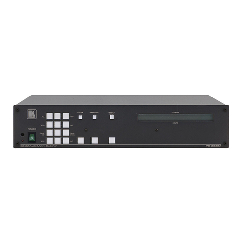
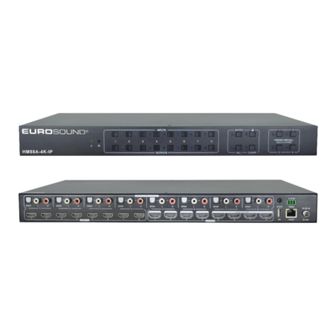
Crestron Electronics CEN-RGBHV32X32 User manual

Crestron CEN-RGBHV32X32
32x32 Matrix Switchers
Operations Guide

This document was prepared and written by the Technical Documentation department at:
Crestron Electronics, Inc.
15 Volvo Drive
Rockleigh, NJ 07647
1-888-CRESTRON
Important Safety Instructions
•Read these instructions.
•Keep these instructions.
•Heed all warnings.
•Follow all instructions.
•Do not use this apparatus near water.
•Clean only with dry cloth.
•Do not block any ventilation openings. Install in accordance
with the manufacturer's instructions.
•Do not install near any heat sources such as radiators, heat
registers, stoves, or other apparatus (including amplifiers) that
produce heat.
•Do not defeat the safety purpose of the polarized or grounding-
type plug. A polarized plug has two blades with one wider than
the other. A grounding-type plug has two blades and a third
grounding prong. The wide blade or the third prong are
provided for your safety. If the provided plug does not fit into
your outlet, consult an electrician for replacement of the
obsolete outlet.
•Protect the power cord from being walked on or pinched
particularly at plugs, convenience receptacles, and the point
where they exit from the apparatus.
•Only use attachments/accessories specified by the
manufacturer.
•Use only with the cart, stand, tripod, bracket or
table specified by the manufacturer or sold with
the apparatus. When a cart is used, use caution
when moving the cart/apparatus combination to
avoid injury from tip-over.
•Unplug this apparatus during lightning storms or when unused
for long periods of time.
•Refer all servicing to qualified service personnel. Servicing is
required when the apparatus has been damaged in any way,
such as power-supply cord or plug is damaged, liquid has been
spilled or objects have fallen into the apparatus, the apparatus
has been exposed to rain or moisture, does not operate
normally, or has been dropped.
•Disconnect power prior to connecting or disconnecting
equipment.
•Do not install in direct sunlight.
•The apparatus must be installed in a way that the power cord
can be removed either from the wall outlet or from the device
itself in order to disconnect the mains power.
•Prevent foreign objects from entering the device.
The lightning flash with arrowhead symbol, within an
equilateral triangle, is intended to alert the user to the
presence of uninsulated “dangerous voltage” within the
product's enclosure that may be of sufficient magnitude to
constitute a risk of electric shock to persons.
The exclamation point within an equilateral triangle is
intended to alert the user to the presence of important
operating and maintenance (servicing) instructions in the
literature accompanying the appliance.
WARNING:
TO REDUCE THE RISK OF FIRE OR ELECTRIC SHOCK,
DO NOT EXPOSE THIS APPARATUS TO RAIN OR
MOISTURE. THE APPARATUS SHALL NOT BE
EXPOSED TO DRIPPING OR SPLASHING. OBJECTS
FILLED WITH LIQUIDS, SUCH AS VASES, SHOULD
NOT BE PLACED ON THE APPARATUS.
WARNING:
TO PREVENT ELECTRIC SHOCK, DO NOT REMOVE
COVER. THERE ARE NO USER SERVICEABLE PARTS
INSIDE. ONLY QUALIFIED SERVICE PERSONNEL
SHOULD PERFORM SERVICE.
CAUTION
RISK OF ELECTRIC SHOCK
DO NOT OPEN
AVIS: RISQUE DE CHOC ELECTRIQUE NE PAS OUVRIR
WARNING:
THIS IS AN APPARATUS WITH CLASS I
CONSTRUCTION. IT SHALL BE CONNECTED TO AN
ELECTRICAL OUTLET WITH AN EARTHING GROUND
TERMINAL.
IMPORTANT:
The CEN-RGBHV32X32 can be used with Class 2 output
wiring.

Regulatory Compliance
Federal Communications Commission (FCC) Compliance Statement
This Class B digital apparatus complies with Canadian ICES-003.
Cet appareil numérique de la classe B est conforme à la norme NMB-003 du Canada.
Industry Canada (IC) Compliance Statement
This device complies with part 15 of the FCC Rules. Operation is subject to the following conditions:
(1) This device may not cause harmful interference and (2) this device must accept any interference received,
including interference that may cause undesired operation.
CAUTION: Changes or modifications not expressly approved by the manufacturer responsible for compliance
could void the user’s authority to operate the equipment.
NOTE: This equipment has been tested and found to comply with the limits for a Class B digital device,
pursuant to part 15 of the FCC Rules. These limits are designed to provide reasonable protection against harmful
interference in a residential installation. This equipment generates, uses and can radiate radio frequency energy
and, if not installed and used in accordance with the instructions, may cause harmful interference to radio
communications. However, there is no guarantee that interference will not occur in a particular installation. If
this equipment does cause harmful interference to radio or television reception, which can be determined by
turning the equipment off and on, the user is encouraged to try to correct the interference by one or more of the
following measures:
Reorient or relocate the receiving antenna
Increase the separation between the equipment and receiver
Connect the equipment into an outlet on a circuit different from that to which the receiver is connected
Consult the dealer or an experienced radio/TV technician for help
As of the date of manufacture, the CEN-RGBHV32X32 has been tested and found to comply with specifications
for CE marking and standards per EMC and Radiocommunications Compliance Labelling.
All brand names, product names and trademarks are the property of their respective owners.
©2010 Crestron Electronics, Inc.


Crestron CEN-RGBHV32X32 32x32 Matrix Switchers
Contents
32x32 Matrix Switchers: CEN-RGBHV32X32 1
Introduction ...............................................................................................................................1
Features and Functions................................................................................................1
Specifications ..............................................................................................................3
Physical Description....................................................................................................5
Setup ........................................................................................................................................16
Network Wiring.........................................................................................................16
Identity Code .............................................................................................................16
Installation.................................................................................................................17
Hardware Hookup ..................................................................................................... 19
Programming Software............................................................................................................23
Earliest Version Software Requirements for the PC .................................................23
Programming with Crestron SystemBuilder.............................................................. 23
Programming with SIMPL Windows ........................................................................23
Example Program ......................................................................................................26
Uploading and Upgrading........................................................................................................ 27
Establishing Communication..................................................................................... 27
Programs and Firmware ............................................................................................ 28
Program Checks ........................................................................................................ 29
Operation .................................................................................................................................30
Using the CEN-RGBHV32X32A with the CEN-RGBHV32X32V.......................... 30
Menu Structure .......................................................................................................... 30
Setup and Information Screens.................................................................................. 31
Routing Signals .........................................................................................................49
Sync Mode................................................................................................................. 50
Problem Solving ......................................................................................................................51
Troubleshooting......................................................................................................... 51
Check Network Wiring..............................................................................................51
Reference Documents................................................................................................52
Further Inquiries ........................................................................................................ 52
Future Updates .......................................................................................................... 52
Return and Warranty Policies ..................................................................................................53
Merchandise Returns / Repair Service ...................................................................... 53
CRESTRON Limited Warranty.................................................................................53
Operations Guide – DOC. 6758A Contents •i


Crestron CEN-RGBHV32X32 32x32 Matrix Switchers
32x32 Matrix Switchers:
CEN-RGBHV32X32
Introduction
Crestron®matrix switchers are designed to provide flexible signal routing of high-res
signals for the most demanding presentation environments. With extremely low
crosstalk, 450 MHz video bandwidth (CEN-RGBHV32X32V), optional audio
(CEN-RGBHV32X32A) and full Crestron control system integration, the
CEN-RGBHV32X32V and CEN-RGBHV32X32A (hereinafter collectively referred
to as “CEN-RGBHV32X32”, except where noted), satisfy the demanding video and
audio requirements of corporate boardrooms and training centers, university lecture
halls, high-tech houses of worship, command and control facilities and live staging
events.
Features and Functions
CEN-RGBHV32X32V
• 32x32 high bandwidth matrix switcher
• Low crosstalk with incredibly flat response
• 450 MHz video bandwidth (-3 dB)
• Input sync detection and Genlock sync input
• Adjustable video blanking
• Selectable input sync impedance (via software)
• Standalone operation with LCD driven front control panel
• Cresnet®or high speed Ethernet communications
• Nine space rack mount installation
• Optional stereo audio matrix switching (with CEN-RGBHV32X32A)
CEN-RGBHV32X32A
• 32x32 stereo audio matrix switcher
• Professional balanced inputs and outputs
• Audio input level compensation
• Audio output volume and mute control
• Adjustable audio blanking
• Controllable via the CEN-RGBHV32X32V or a control system
• Cresnet or high speed Ethernet communications
• Three-space rack mount installation
Operations Guide – DOC. 6758A 32x32 Matrix Switchers: CEN-RGBHV32X32 •1

32x32 Matrix Switchers Crestron CEN-RGBHV32X32
High Bandwidth Matrix Router (CEN-RGBHV32X32V)
The CEN-RGBHV32X32V is a high bandwidth matrix switcher capable of routing
up to 32 computer or video sources to up to 32 display devices. Its five matrix levels
accommodate any combination of analog RGBHV, HD/component, S-video and
composite signals. Proven flat response achieves optimum performance even at the
highest bandwidth. Selectable sync impedance on every input helps accommodate
varying cable lengths.
Glitch-free Switching (CEN-RGBHV32X32V)
Video-follow-sync switching ensures a glitch-free transition when selecting between
non-synchronous sources. Blanking time is independently adjustable per output from
0 to 10 seconds, allowing each display device time to lock to the new sync signal
before displaying the video image whenever a new source is selected. A sync
reference input is also provided to support vertical interval switching of genlocked
sources.
Sync Detection (CEN-RGBHV32X32V)
Video sync detection on each input measures the H and V sync rates of every RGB
source and allows their values to be viewed on the front panel display, control
system touchpanel or RoomView®software.
Full-featured Front Panel (CEN-RGBHV32X32V)
The CEN-RGBHV32X32V is fully operable out of the box for use as a standalone
switcher. Featuring an informative LCD display and quick adjust knob, the front
panel supports essential switcher operation without requiring a computer or control
system. All signal routing (and audio compensation settings with optional audio
matrix) are stored in non-volatile memory onboard the switcher.
Customizable label strips are provided on the front panel for clear designation of its
inputs and outputs using Crestron Engraver software or standard 3/8” tape labels.
Names may also be entered through software to appear on the LCD display during
operation. For security, the front panel controls can be password protected or locked
out.
Professional Stereo Audio Matrix (CEN-RGBHV32X32A)
Supporting both balanced and unbalanced line level signals, the
CEN-RGBHV32X32A can route any of 32 inputs to any or all of 32 outputs.
Programmable input level compensation helps ensure compatibility with a wide
range of pro and semi-pro sources. Automatic blanking achieves a pop free transition
when switching between sources. Every output includes volume and mute control,
providing multiple channels of real-time controllable audio signal distribution to feed
multi-zone amplifiers, assistive listening and recording equipment. Audio breakaway
capability allows any audio input or output to be linked with its respective video
channel or switched independently.
Crestron System Integration
Via Cresnet®or high speed Ethernet, Crestron switchers offer the ultimate in control
system integration with every function accessible through SIMPL™ Windows or
SystemBuilder™ without deciphering cryptic protocols. Up to 10 routing presets can
be saved onboard the CEN-RGBHV32X32 for instant recall. Integration with any
2-Series Control system also provides the gateway to Crestron’s RoomView®Asset
Management Software and e-Control®2 XPanel Solutions for remote monitoring and
control.
2 •32x32 Matrix Switchers: CEN-RGBHV32X32 Operations Guide – DOC. 6758A

Crestron CEN-RGBHV32X32 32x32 Matrix Switchers
Combining the CEN-RGBHV32X32A with a CEN-RGBHV32X32V provides a
complete yet simplified solution for routing all kinds of AV and computer sources to
feed a facility full of video displays and audio amplifiers. A single 25-pin cable
(included with the CEN-RGBHV32X32A) is all that is required to link the two
components together. When linked, the two components operate as one, allowing
audio-follow-video or audio breakaway capability, with full setup and control
enabled from the RGB switcher’s front panel as well as from a control system.
Specifications
Specifications for the CEN-RGBHV32X32 are listed in the following table.
CEN-RGBHV32X32 Specifications
SPECIFICATION DETAILS
Video/RGB
(CEN-RGBHV32X32V)
Switcher 32 x 32 (x5) crosspoint matrix, adjustable
blanking, sync detection, selectable input
termination, vertical interval switching using
genlock input
Signal Types RGB and composite, S-video or component
video (does not transcode)
Video/HDTV Formats NTSC or PAL, HDTV up to 1080i/1080p
RGB Formats RGBHV, RGBS, RGsB or YUV
Gain 0 dB (75 Ωterminated)
Bandwidth 450 MHz (-3 dB) fully loaded
Blanking Time Adjustable 0 to 10 seconds, 0.5 second steps
Crosstalk ≤-65 dB @ 5 MHz
≤-47 dB @ 100 MHz
Audio
(CEN-RGBHV32X32A)
Switcher 32 x 32 stereo crosspoint matrix, input
compensation, output volume and mute
control, adjustable blanking, audio breakaway
(when linked to CEN-RGBHV32X32V)
Input Compensation ±10 dB in 0.5 dB steps
Output Volume Control -60 dB to + 20 dB in 0.5 dB steps
Blanking Time Adjustable 0 to 10 seconds, 0.5 second steps
Frequency Response 20 Hz to 20 kHz ±0.5 dB
Ethernet 10/100 BASE-T, static IP or DHCP/DNS,
auto-negotiating, auto discovery, full/half
duplex, TCP/IP, UDP/IP, CIP
Power Requirements
Main Power CEN-RGBHV32X32V:
5 Amps @ 100-240 Volts AC, 50/60 Hz
CEN-RGBHV32X32A:
2.4 Amps @ 100-240 Volts AC, 50/60 Hz
Cresnet Power Usage None
Default Net ID 33
Minimum 2-Series Control
System Update File1, 2
Version 3.137 or later
(Continued on following page)
Operations Guide – DOC. 6758A 32x32 Matrix Switchers: CEN-RGBHV32X32 •3

32x32 Matrix Switchers Crestron CEN-RGBHV32X32
CEN-RGBHV32X32 Specifications (Continued)
SPECIFICATION DETAILS
Environmental
Temperature 32º to 104ºF (0º to 40ºC)
Humidity 10% to 90% RH (non-condensing)
Enclosure
Chassis
(CEN-RGBHV32X32V)
Metal, vented front, fan cooled
Chassis
(CEN-RGBHV32X32A)
Metal, vented sides
Faceplate
(CEN-RGBHV32X32V)
Detachable metal panel with polycarbonate
label overlay
Faceplate
(CEN-RGBHV32X32A)
Metal with polycarbonate label overlay
Mounting
(CEN-RGBHV32X32V)
19-inch rack mountable3
(rack ears built in)
Mounting
(CEN-RGBHV32X32A)
Freestanding or 19-inch rack mountable3
(adhesive feet included, rack ears included)
Dimensions
(CEN-RGBHV32X32V)
Height 15.72 in (400 mm)
Width 19.00 in (483 mm)
Depth 18.96 in (482 mm)
Dimensions
(CEN-RGBHV32X32A)
Height 5.20 in (133 mm)
Width (without ears) 17.03 in (433 mm)
Width (with ears) 19.00 in (483 mm)
Depth 19.88 in (505 mm)
Weight
(CEN-RGBHV32X32V)
50 lbs (22.7 kg)
Weight
(CEN-RGBHV32X32A)
16 lbs (7.3 kg)
1. The latest software versions can be obtained from the Crestron website. Refer to the NOTE following
these footnotes.
2. Crestron 2-Series control systems include the AV2 and PRO2. Consult the latest Crestron Product
Catalog for a complete list of 2-Series control systems.
3. 9U for CEN-RGBHV32X32V, 3U for CEN-RGBHV32X32A.
NOTE: Crestron software and any files on the website are for authorized Crestron
dealers and Crestron Authorized Independent Programmers (CAIP) only. New users
may be required to register to obtain access to certain areas of the site (including the
FTP site).
4 •32x32 Matrix Switchers: CEN-RGBHV32X32 Operations Guide – DOC. 6758A

Crestron CEN-RGBHV32X32 32x32 Matrix Switchers
Physical Description
This section provides information on the connections, controls and indicators
available on your CEN-RGBHV32X32.
CEN-RGBHV32X32V Front View
Operations Guide – DOC. 6758A 32x32 Matrix Switchers: CEN-RGBHV32X32 •5

32x32 Matrix Switchers Crestron CEN-RGBHV32X32
CEN-RGBHV32X32V Rear View
6 •32x32 Matrix Switchers: CEN-RGBHV32X32 Operations Guide – DOC. 6758A

Crestron CEN-RGBHV32X32 32x32 Matrix Switchers
CEN-RGBHV32X32A Front View
CEN-RGBHV32X32A Rear View
Operations Guide – DOC. 6758A 32x32 Matrix Switchers: CEN-RGBHV32X32 •7

32x32 Matrix Switchers Crestron CEN-RGBHV32X32
CEN-RGBHV32X32V Overall Dimensions (Front View)
9
11 12 13
1 2 3
4
5
6
7
8
10 15
14
19.00 in
(483 mm)
15.72 in
(400 mm)
8 •32x32 Matrix Switchers: CEN-RGBHV32X32 Operations Guide – DOC. 6758A

Crestron CEN-RGBHV32X32 32x32 Matrix Switchers
CEN-RGBHV32X32V Overall Dimensions (Top View)
17.58 in
(447 mm)
18.36 in
(467 mm)
18.96 in
(482 mm)
0.60 in
(16 mm)
Operations Guide – DOC. 6758A 32x32 Matrix Switchers: CEN-RGBHV32X32 •9

32x32 Matrix Switchers Crestron CEN-RGBHV32X32
CEN-RGBHV32X32V (Rear View)
16
17
18
19
20
21
22
23
24
25
16
CEN-RGBHV32X32A Overall Dimensions (Front View)
11
10
19.00 in
(483 mm)
5.20 in
(133 mm)
26
10 •32x32 Matrix Switchers: CEN-RGBHV32X32 Operations Guide – DOC. 6758A

Crestron CEN-RGBHV32X32 32x32 Matrix Switchers
CEN-RGBHV32X32A Overall Dimensions (Top View)
17.03 in
(433 mm)
19.62 in
(499 mm)
19.88 in
(505 mm)
CEN-RGBHV32X32A (Rear View)
20
21
22
23
24
25
29
27 28
Operations Guide – DOC. 6758A 32x32 Matrix Switchers: CEN-RGBHV32X32 •11

32x32 Matrix Switchers Crestron CEN-RGBHV32X32
Connectors, Controls & Indicators
# CONNECTORS1,
CONTROLS &
INDICATORS
DESCRIPTION
1 LCD DISPLAY2Green LCD alphanumeric, adjustable
backlight;
2 lines x 20 characters per line;
Displays inputs/outputs by name, scan rates,
audio levels, IP configuration and setup
menus
2 SOFTKEYS2(4) Pushbuttons for activation of LCD driven
functions and pass code entry
3 IN (1 – 32)2(32) Pushbuttons & red LEDs, select input to
be routed
4 CLEAR2(1) Pushbutton & red LED, clears all matrix
routing
5 SYNC2, 3 (1) Pushbutton & red LED, displays input
sync rates
6 VIEW2(1) Pushbutton & red LED, toggles View
mode on/off
7 A2(1) Pushbutton & red LED, selects audio
routing view
8 V2(1) Pushbutton & red LED, selects video
routing view
9 TAKE2(1) Pushbutton & red LED, executes routing
10 HW-R (1) Recessed miniature pushbutton for
hardware reset, reboots the switcher
11 COMPUTER
USB
Pin 2 Pin 1
Pin 3 Pin 4
(1) USB Type B female;
USB 1.1 computer console port
(6 foot cable included)
PIN DESCRIPTION
1 +5 VDC
2 Data -
3 Data +
4 Ground
12 MENU2(1) Pushbutton, steps menu back one level
13 ENTER2(1) Pushbutton, executes highlighted menu
or value
14 QUICK-ADJUST
KNOB2
(1) Continuous turn rotary encoder, adjusts
menu parameters
15 OUT (1 – 32)2(32) Pushbuttons & red LEDs, select output
destination
16 (VIDEO) OUT (1 – 32)2
(32) Sets of (5) BNC female, each set
comprising (3) high bandwidth video inputs
plus (2) sync inputs;
Output level: 0.2 to 5.0 Vp-p
Output impedance: 75 Ωnominal
Return loss: < -30 dB @ 5 MHz
(Continued on following page)
12 •32x32 Matrix Switchers: CEN-RGBHV32X32 Operations Guide – DOC. 6758A

Crestron CEN-RGBHV32X32 32x32 Matrix Switchers
Connectors, Controls & Indicators (Continued)
# CONNECTORS1,
CONTROLS &
INDICATORS
DESCRIPTION
17 TO AUDIO SWITCHER
CONTROL2
(1) DB25F;
Accepts connection from optional
CEN-RGBHV32X32A audio matrix
(sold separately)
18 (VIDEO) IN (1 – 32)2
(32) Sets of (5) BNC female, each set
comprising (3) high bandwidth video inputs
plus (2) sync inputs;
Input level: 0.2 to 5.0 Vp-p
RGB input impedance: 75 Ωnominal
Sync input impedance: 75 Ω(default)
or 510 Ω, independently selectable for H and
V per input
Return loss: < -30 dB @ 5 MHz
Sync detection on every input connector
19 VIDEO REF IN2
(2) BNC female;
Genlock sync reference input and loop
through, unterminated
20 G
(1) 6-32 screw, chassis ground lug
21 FUSE HOLDER4
Main fuse holder
CEN-RGBHV32X32V: 20 mm x 5 mm
250 Volt, 5 A, time-lag
CEN-RGBHV32X32A: 20 mm x 5 mm
250 Volt, 1 A, time-lag
22 POWER SWITCH
(1) Rocker switch, turns main power on or off
(Continued on following page)
Operations Guide – DOC. 6758A 32x32 Matrix Switchers: CEN-RGBHV32X32 •13

32x32 Matrix Switchers Crestron CEN-RGBHV32X32
Connectors, Controls & Indicators (Continued)
# CONNECTORS1,
CONTROLS &
INDICATORS
DESCRIPTION
23 100-120/200-240V~
350W 50/60Hz2
100-240V ~2.4A
50/60Hz6
(1) IEC socket, main power input;
Mates with removable power cord (included)
24 NET
(1) 4-pin 3.5 mm detachable terminal block;
Cresnet slave port, connects to Cresnet
control network;
Does not draw power from the network
24: Power (24 Volts DC)
Y: Data
Z: Data
G: Ground
25 LAN5
YELLOW
LED
GREEN
LED
PIN 1
PIN 8
(1) 8-wire RJ-45 with two LED indicators;
10/100BASE-T Ethernet port;
Green LED indicates link status;
Yellow LED indicates Ethernet activity
PIN SIGNAL PIN SIGNAL
1 TX + 5 N/C
2 TX - 6 RC -
3 RC+ 7 N/C
4 N/C 8 N/C
26 PWR LED6(1) Green LED, indicates main power is
connected and turned on
27 (AUDIO) INPUTS
(1 – 32)6
(32) 5-pin 3.5 mm detachable terminal
blocks;
Balanced/unbalanced stereo line level inputs;
Maximum input level: 12 Vrms balanced,
6 Vrms unbalanced
Input impedance: 20 kΩbalanced,
10 kΩunbalanced
28 (AUDIO) OUTPUTS
(1 – 32)6
(32) 5-pin 3.5 mm detachable terminal
blocks;
Balanced/unbalanced stereo line level
outputs;
Maximum output level: 12 Vrms balanced,
6 Vrms unbalanced;
Output impedance: 100 Ωbalanced,
50 Ωunbalanced
(Continued on following page)
14 •32x32 Matrix Switchers: CEN-RGBHV32X32 Operations Guide – DOC. 6758A
This manual suits for next models
2
Table of contents
Other Crestron Electronics Matrix Switcher manuals

