Model: HED2040 1x40W / HED2050 1X50W
LED
LED current selection
+
-
1-10V
DALI
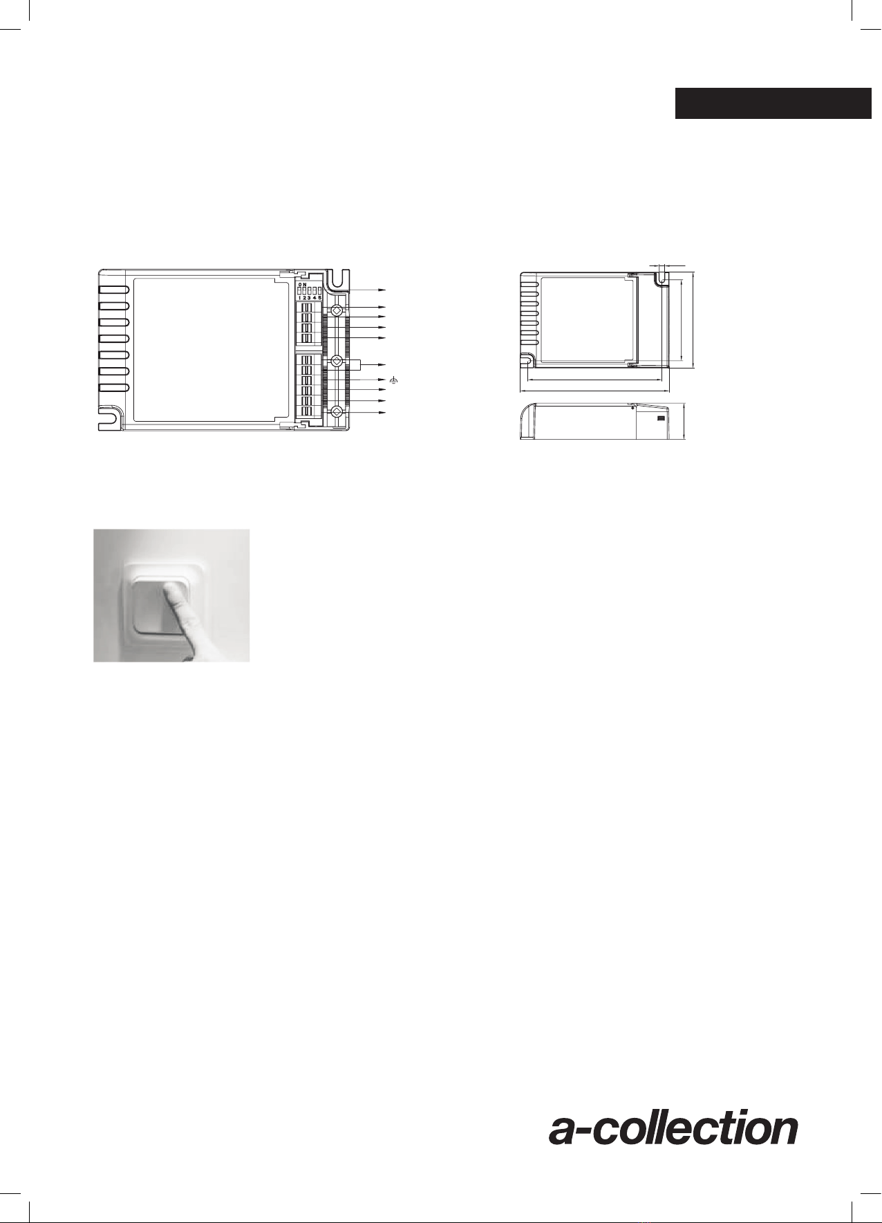
111
4.5
67
79.2
30
123.2
Switch-Dim
N
L
+
-
1 (8)
DALI LED Driver
Model: HED2040
Instruction Manual
MECHANICAL STRUCTURE
Model: HED2040 1x40W / HED2050 1x50W
LED current selection
LED
_
+
1-10V
_
+
DALI
N
L
Switch-Dim
ENGLISH
LED CURRENT & VOLTAGE SELECTION
The driver is suitably configured upon delivery from the factory.
SWITCH - DIM
• On/off control: short push (<0.4s) on the switch. Note: Short push should be
at least 0.12s, and the time interval between two pushes should be longer
than 0.12s also.
• Stepless dimming: long push (>0.9s) on the switch.
• For fine tuning of light level: with every other long push, the light level goes
to the opposite direction.
• Built--in with permanent memory: light returns to the previous dimming level
when switched off and on again, even at power failure.
SYNCHRONIZATION
Up to 64pcs drivers can be connected to the same switch, thanks to the programme. This means there is no need
for any additional synchrony wire in large installation, where many drivers should be controlled by one switch.
Please follow the step below to achieve synchronization function if more than one driver are connected to the
same push button:
• Do a long push for more than 15s, then the system is synchronized and all lights in the group dim down to 50%.
PERMANENT MEMORY
This driver has built-in permanent memory against power failure, which means the light always starts up at the
previous level when it was switched off last time.
MANUAL OVERRIDE
DALI and swtich-Dim. can be connected at the same time, to enable manual override function for end-users to
switch on/off or adjust the dimming level by the push-switch. This feature makes the product more user-friendly,
and could provide more options for some extra-ordinary demands.
* Short push (<0.4s): on/off control.
* Long push (>0.9s): dim up/down the dimming level.
* If customers do not want to have this manual override function, just leave the “switch” terminal alone, and
not connected to any wire.
* This manual override is only valid before the next DALI command, meanning the latest action, either from
DALI, switch-Dim, stays in control.