6 / 14
ALL AIR MOTORS
1. Lubricate Air Motor as per Installation section on page 3.
2. Check exhaust muffler filter every 500 hours. Clean or
replace as necessary.
3. If the Air motor starts to run slowly or is sluggish, flushing
the motor with solvent may restore its performance due to
excessive contamination from oil, moisture and foreign
particles. Use only Gast #AH255B Flushing Solvent or
equivalent for this.
4. This cleaning operation should only be carried out in a well
ventilated area.
5. Wear eye protection.
6. Do not use combustible solvents for flushing.
7. Disconnect the airline and muffler. Add about 100ml (4 fluid
oz) of solvent into the air intake port of the motor. Rotate
the motor by hand in both directions for a few minutes.
8. Re-connect the airline and cover the exhaust port with a
cloth. Apply low pressure 0.7bar (10psi) and re-start the
motor. Run until no more traces of solvent can be seen.
9. The motor should be running smoothly. If not, then a
re-build may be required (see QS-4016 Replacement of
Parts).
REPLACEMENT OF PARTS
QS-5012-1-CE REPLACEMENT OF PARTS
(SEE FIGS 5 & 6)
Before attempting any MAINTENANCE of agitators
on pressure feed tanks, the tanks must be relieve of
pressure as stated previously.
!
WARNING
1. Turn off and disconnect the mains air supply hose with the
air adjusting valve (65).
2. Loosen the upper clamp screw (61) and remove the air
motor and gearbox assembly.
3. Separate the motor and gearbox by removing the four
3/8-16 bolts (51) and lock washers (52) and pulling the air
motor away from the gearbox .
4. Remove the key from the motor shaft.
5. For the Air motor refer to 31-418 Air motor section.
6. When reassembling the air motor and gearbox, apply
grease to the O.D. of the air motor shaft and the I.D. of the
gearbox shaft. Recommended grease: 41-4458-K.
GEARBOX
Gearbox can only be replaced as a complete unit. Check oil
level of new unit before use.
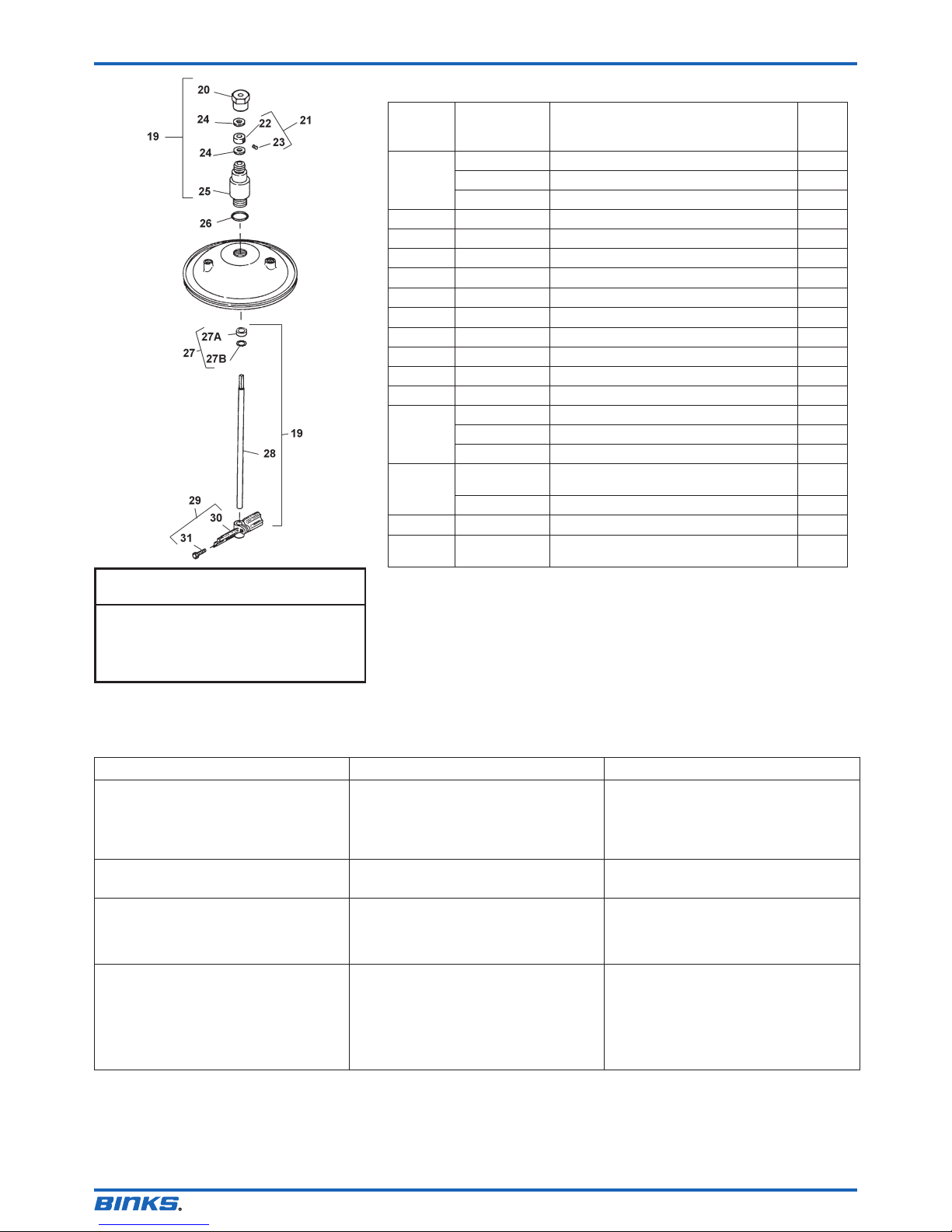
QMS-431-CE, 433-CE AND 434-CE AGITATOR
REPLACEMENT OF PARTS (SEE FIG. 7)
Before attempting any MAINTENANCE of agitators
on pressure feed tanks, the tanks must be relieve of
pressure as stated previously.
!
WARNING
1. Remove lid from pressure feed tank.
2. Remove paddles by loosening screw(s) (31).
3. Unscrew retaining nut (20) and remove.
4. Hold the shaft (28), loosen set screw (23) on the collar
(22). The collar (22) and washers (24) can now be
removed.
5. The shaft can now be withdrawn from the bearing housing
(25). Be careful with the shaft seal (27) as any burrs or
dried paint could damage the lip seal.
6. If the O ring (26) is to be replaced, unscrew and remove
the bearing assembly (25).
7. Examine the Shaft seal (27A) for any damage. If it needs
replacement, prise out the retaining clip (27B), then the
seal (27A). Take care not to damage the seat in the bearing
housing (25).
8. Check the size of the oilite bearings in the housing (25) for
wear. These are 15.6mm when new. Replace when the size
is 15.9mm (0.626”) or greater.
9. Take a new seal (27A) and apply a small amount of water
or oil to the outside to lubricate the fitted O ring.
10. Place the seal in the housing (25) O ring first with the
grooves facing outwards. Press the seal in making sure it
is seated fully in the housing.
11. Clean the O ring groove in the housing (25) and make
sure the seating surface on the tank lid is clean. Place the
O ring (26) in the groove and lightly lubricate it with water
or light oil. Screw the housing (25) into the lid and fully
tighten with a spanner.
12. Take the shaft (28) and insert the paddle end into the top
of the housing (25) and feed through, taking care when
feeding through the Shaft seal (27A).
13. Hold the shaft (28) with the groove about 12mm from then
top of the housing (25) and slip thrust washer (24) then
collar (22) over the end. Align the set screw (23) in the collar
(22) with the groove and tighten. Fit 2nd washer (24).
14. Screw on retainer nut (20) onto the bearing housing (25)
and tighten with a spanner.
15. Slide paddle(s) (29) over the shaft and position as shown
in Fig. 2 in the installation section.
16. Re-fit the drive motor QS-5012-1-CE as per installation
section.
QMS-430-CE AND PT-428-CE/PT-419-CE
REPLACEMENT OF PARTS (FIGS 8 & 9)
Before attempting any MAINTENANCE of agitators
on pressure feed tanks, the tanks must be relieve of
pressure as stated previously.
!
WARNING
1. Turn off air supply with the air adjusting valve (21) and
disconnect the main air supply hose.
2. Remove Lid from pressure feed tank.
3. Remove propeller (55).
4. Loosen screws (49) and remove retainer (32A), Shaft (54)
with the propeller (55).
5. Loosen screws (34A) or (49) and Air motor (33) or (35) can
be withdrawn from the housing (34) or (48).
6. For replacement of parts procedure for the Air motor see
section for QS-4016 below. Some of the references are
different but the procedure is the same.
7. Examine the Seal (50) for damage or wear. Only remove if
it needs replacing.
8. Take a new seal (50A) and apply a small amount of water
or oil to the outside to lubricate the fitted O ring.