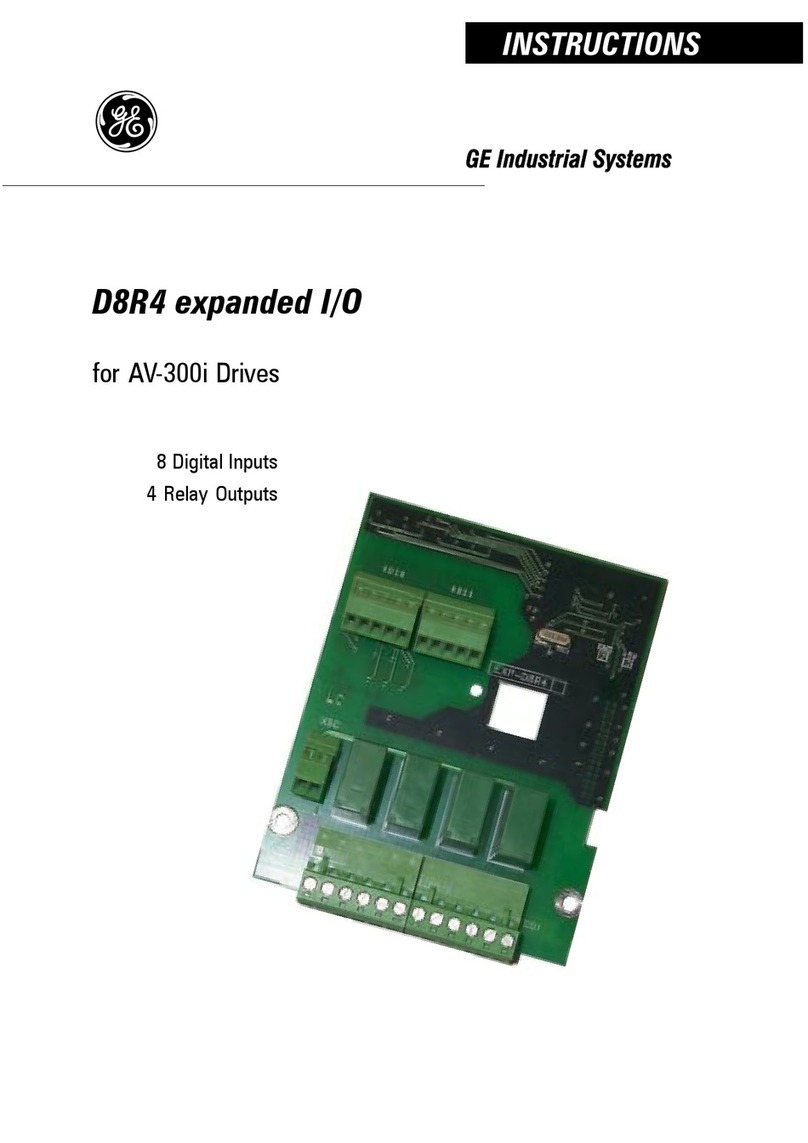
GE D20A6 User manual

12 Digital Inputs
8 Digital Outputs
2 Analog Inputs
2 Analog Outputs (V)
2 Analog Outputs (I)
D20A6 expanded I/O
for AV-300i Drives
GE Industrial Systems
INSTRUCTIONS

© 2000 General Electric Company, USA.
All rights reserved.
Supersedes GEI-100427 05/99
These instructions do not purport to cover all details
or variations in equipment, nor to provide every
possible contingency to be met during installation,
operation, and maintenance. If further information
is desired or if particular problems arise that are not
covered sufficiently for the purchaser’s purpose,
the matter should be referred to GE Industrial
Systems,Salem,Virginia,USA.
This document contains proprietary information of
General Electric Company, USA and is furnished to
its customer solely to assist that customer in the
installation, testing, operation, and/or maintenance
of the equipment described. This document shall
not be reproduced in whole or in part nor shall its
contents be disclosed to any third party without
the written approval of GE Industrial Systems.
AV300i is a trademark of General Electric Company. USA.
National Electric code and NEC are registered trademarks of the
National Fire Protection Association.

SAFETY SYMBOL LEGEND / LÉGENDE DES SIGNES
DE SÉCURITÉ
WARNING!Commands attention to an operating procedure, practice,
condition, or statement which, if not strictly observed,
could result in personal injury or death.
Attire l’attention sur les modes d’utilisation et les
procédés et conditions d’exploitation qui, en cas
d’inobservation, pourraient entraîner des blessures
corporelles ou la mort.
CAUTION!Commands attention to an operating procedure, practice,
condition, or statement which, if not strictly observed,
could result in damage or destruction of equipment.
The seriousness of the injuries and of the damages which
could be caused by the non- observance of such
indications, depends on the different conditions.
Anyway, the instructions given below should always be
followed with the highest attention.
Attire l’attention sur les modes d’utilization et les
procédés et conditions d’exploitation qui, en cas
d’inobservation, pourraient entraîner la détérioration
ou la destruction des appareils.
La gravité des blessures et des dommages matériels
possibles dépendent de différent facteurs. Toutefois, les
instructions mentionées ci-dessous devraient être
toujours suivies avec la plus grande attention.
NOTE!Commands attention to an operating procedure, practice,
condition, or statement that must be highlighted.
Attire l’attention sur les modes d’utilization et les
procédés et conditions d’exploitation qui présentent
un intéret particulier.


5
—————— I/O Expansion card ——————
D20A6
Table of Contents
SAFETY SYMBOL LEGEND / LÉGENDE DES SIGNES DE
SÉCURITÉ ............................................................................... 3
Chapter 0 - SAFETY PRECAUTIONS / PRECAUTIONS DE
SECURITÉ ............................................................................... 6
Chapter 1 - INTRODUCTION ..................................................... 12
Chapter 2 - MOUNTING ............................................................ 14
Chapter 3 - TERMINAL BOARD POINTS................................... 15
3.1 DIGITAL INPUTS TERMINAL BOARD POINTS .................................. 15
3.2 DIGITAL OUTPUTS TERMINAL BOARD POINTS ............................... 15
3.3 ANALOG INPUTS TERMINAL BOARD POINTS ................................. 16
3.4 ANALOG OUTPUTS TERMINAL BOARD POINTS .............................. 16
3.5 FUNCTIONAL OVERVIEW ................................................................... 17
Chapter 4 - JUMPERS .............................................................. 18
Chapter 5 - LEDS ...................................................................... 18
Chapter 6 - TECHNICAL DATA .................................................. 19
Dimensions and Weight ............................................................................. 19
General Data ............................................................................................. 20
Digital Inputs ............................................................................................. 20
Digital Outputs ........................................................................................... 20
Analog Inputs ............................................................................................ 20
Voltage Analog Outputs ............................................................................. 21
Current Analog Outputs .............................................................................. 21
Temperature .............................................................................................. 21
Chapter 7 - ACCESSORIES ....................................................... 22
Chapter 8 - MAXIMUM WIRE SIZES ........................................ 22

—————— I/O Expansion card ——————
6
GEI-100427A
Chapter 0 - SAFETY PRECAUTIONS / PRECAUTIONS
DE SECURITÉ
NOTE!The terms “Inverter”, “Controller” and “Drive” are
sometimes used interchangably throughout the indus-
try. We will use the term “Drive” in this document
Les mots “Inverter”, “Controller” et “Drive” sont
interchangeables dans le domaine industriel. Nous
utiliserons dans ce manuel seulement le mot “Drive”.
WARNING! / ATTENTION!
- According to the EEC standards the AV300i and accessories must be used
only after checking that the machine has been produced using those safety
devices required by the 89/392/EEC set of rules.
Drive systems cause mechanical motion. It is the responsibility of the
user to insure that any such motion does not result in an unsafe condition.
Factory provided interlocks and operating limits should not be bypassed
ormodified.
- NeveropenthedeviceorcoverswhiletheAC Input power supply isswitched
on.Minimumtimetowaitbeforeworkingontheterminalsorinternaldevices
islistedin section 5.11onHardware&Quick Start UpGuide.
- If the front plate has to be removed because the ambient temperature is
higher than 40 degrees, the user has to ensure that no occasional contact
with live parts will occur.
- Always connect the Drive to the protective ground (PE) via the marked
connection terminals (PE2) and the housing (PE1). Adjustable Frequency
Drives and AC Input filters have ground discharge currents greater than
3.5 mA. EN 50178 specifies that with discharge currents greater than 3.5
mA the protective conductor ground connection (PE1) must be fixed type
and doubled for redundancy.
- Thedrive maycause accidentalmotion in theevent ofa failure, evenif itis
disabled, unless it has been disconnected from the AC input feeder.
- Selon les normes EEC, les drives AV300i et leurs accessoires doivent être
employés seulement après avoir verifié que la machine ait été produit
avec les même dispositifs de sécurité demandés par la réglementation

7
—————— I/O Expansion card ——————
D20A6
89/392/EEC concernant le secteur de l’industrie.
Les systèmes provoquent des mouvements mécaniques. L’utilisateur est
responsable de la sécurité concernant les mouvements mécaniques. Les
dispositifs de sécurité prévues par l’usine et les limitations operationelles
ne doivent être dépassés ou modifiés.
- Ne jamais ouvrir l’appareil lorsqu’il est suns tension. Le temps minimum
d’attente avant de pouvoir travailler sur les bornes ou bien à l’intérieur de
l’appareil est indiqué dans la section 5.11 (Instruction manual).
- Si la plaque frontale doit être enlevée pour un fonctionnement avec la
température de l’environnement plus haute que 40°C, l’utilisateur doit
s’assurer, par des moyens opportuns, qu’aucun contact occasionnel ne
puisse arriver avec les parties sous tension.
- L’appaeil peut rédémarrer de façon accidentel en cas d’anomalie, sauf s’il
a été déconnecté du reseau.
- Effectuer toujours des connexions de terre (PE) par le biais des bornes
(PE2) et du chassis (PE1). Le courant de dispersion vers la terre est
supérieur à 3,5 mA. Selon EN 50178 il faut prévoir dans ces cas une
double connexion à terre.
WARNING! - ELECTRICAL SHOCK AND BURN HAZARD / ATTENTION!
– DÉCHARGE ÉLECTRIQUE ET RISQUE DE BRÚLURE :
When using instruments such as oscilloscopes to work on live equipment, the
oscilloscope’s chassis should be grounded and a differential amplifier input
should be used. Care should be used in the selection of probes and leads and
in the adjustment of the oscilloscope so that accurate readings may be made.
See instrument manufacturer’s instruction book for proper operation and
adjustments to the instrument.
Lorsde l’utilisationd’instruments (parexample oscilloscope) surdes systémes
en marche, le chassis de l’oscilloscope doit être relié à la terre et un
amplificateur différentiel devrait être utilisé en entrée.
Les sondes et conducteurs doivent être choissis avec soin pour effectuer les
meilleures mesures à l’aide d’un oscilloscope. Voir le manuel d’instruction
pour une utilisation correcte des instruments.
WARNING! - FIRE AND EXPLOSION HAZARD / ATTENTION! – RISQUE
D’INCENDIES ET D’EXPLOSIONS:
Fires or explosions might result from mounting Drives in hazardous areas such
as locations where flammable or combustible vapors or dusts are present.

—————— I/O Expansion card ——————
8
GEI-100427A
Drivesshould beinstalled away fromhazardous areas,evenif usedwith motors
suitable for use in these locations.
L’utilisation des drives dans des zônes à risques (présence de vapeurs ou de
poussières inflammables), peut provoquer des incendies ou des explosions.
Les drives doivent être installés loin des zônes dangeureuses, et équipés de
moteurs appropriés.
WARNING! - STRAIN HAZARD / ATTENTION À L’ÉLÉVATION:
Improper lifting practices can cause serious or fatal injury. Lift only with
adequate equipment and trained personnel.
Une élévation inappropriée peut causer des dommages sérieux ou fatals. Il
doit être élevé seulement avec des moyens appropriés et par du personnel
qualifié.
WARNING! - ELECTRIC SHOCK HAZARD / ATTENTION! - CAS DE
DECHARGE ELECTRIQUE:
- Drives and motors must be grounded according to NEC.
- Replace all covers before applying power to the Drive. Failure to do so
may result in death or serious injury.
- Adjustable frequency drives are electrical apparatus for use in industrial
installations. Parts of the Drives are at high voltage during operation. The
electrical installation and the opening of the device should therefore only
be carried out by qualified personnel. Improper installation of motors or
Drives may therefore cause the failure of the device as well as serious
injury to persons or material damage. Follow the instructions given in this
manual and observe the local and national safety regulations applicable.
- Tous les moteurs et les drives doivent être mis à la terre selon le Code
Electrique National ou équivalent.
- Remettre tous les capots avant de mettre sous tension le drive. Des erreurs
peuvent provoquer de sérieux accidents ou même la mort.
- Les drives à fréquence variable sont des dispositifs électriques utilisés
dans des installations industriels. Une partie des drives sont sous tension
pendant l’operation. L’installation électrique et l’ouverture des drives
devrait être executé uniquement par du personel qualifié. De mauvaises
installations de moteurs ou de drives peuvent provoquer des dommages
materiels ou blesser des personnes.On doit suivir les instructions donneés
dans ce manuel et observer les régles nationales de sécurité.

9
—————— I/O Expansion card ——————
D20A6
CAUTION! / PRECAUTION!:
- Do not connect power supply voltage that exceeds the standard
specificationvoltagefluctuation permissible. Ifexcessive voltageisapplied
to the Drive, damage to the internal components will result.
- Do not operate the Drive without the ground wire connected. The motor
chassis should be grounded to earth through a ground lead separate from
all other equipment ground leads to prevent noise coupling.
- The grounding connector shall be sized in accordance with the NEC or
Canadian Electrical Code. The connection shall be made by a UL listed or
CSA certified closed-loop terminal connector sized for the wire gauge
involved. The connector is to be fixed using the crimp tool specified by
the connector manufacturer.
- Donot performa megger testbetween the Driveterminals oronthe control
circuitterminals.
- Because the ambient temperature greatly affects Drive life and reliability,
do not install the Drive in any location that exceeds the allowable tempe-
rature. Leave the ventilation cover attached for temperatures of 104° F
(40°C)or below.
- If the Drive’s Fault Alarm is activated, consult the TROUBLESHOOTING
section of Hardware & Quick Start Up Guide., and after correcting the
problem,resumeoperation. Do not resetthe alarmautomatically byexternal
sequence, etc.
- Be sure to remove the desicant dryer packet(s) when unpacking the Drive.
(Ifnot removedthesepackets maybecomelodged inthe fan orair passages
and cause the Drive to overheat).
- The Drive must be mounted on a wall that is constructed of heat resistant
material. While the Drive is operating, the temperature of the Drive's
cooling fins can rise to a temperature of 194° F (90°C).
- Do not touch or damage any components when handling the device.
Changing of isolation gaps or removing the isolation covers is not
permissible.
- Protect the device from disallowed environmental conditions (tempera-
ture, humidity, shock etc.)
- No voltage should be connected to the output of the frequency inverter
(terminals U2, V2 W2). The parallel connection of several frequency in-
verters via the outputs and the direct connection of the inputs and outputs
(bypass) are not permissible.

—————— I/O Expansion card ——————
10
GEI-100427A
- A capacitative load (e.g. Var compensation capacitors) should not be con-
nected to the output of the frequency inverter (terminals U2, V2, W2).
- The electrical commissioning should only be carried out by qualified per-
sonnel, who are also responsible for the provision of a suitable ground
connection and a protected power supply feeder in accordance with the
local and national regulations. The motor must be protected against
overloads.
- No dielectric tests should be carried out on parts of the frequency inverter.
A suitable measuring instrument (internal resistance of at least 10 kΩ/V)
should be used for measuring the signal voltages.
- Ne pas raccorder de tension d’alimentation dépassant la fluctuation de
tensionpermise parles normes. Dansle casd’ une alimentationen tension
excessive, des composants internes peuvent être endommagés.
- Ne pas faire fonctionner le drive sans prise de terre. Le chassis du moteur
doit être mis à la terre à l’aide d’un connecteur de terre separé des
autres pour éviter le couplage des perturbations. Le connecteur de terre
devrait être dimensionné selon la norme NEC ou le Canadian Electrical
code. Le raccordement devrait être fait par un connecteur certifié et
mentionné à boucle fermé par les normes CSA et UL et dimensionné pour
l’épaisseur du cable correspondant. Le connecteur doit être fixé a l’aide
d’un instrument de serrage specifié par le producteur du connecteur.
- Ne pas exécuter un test megger entre les bornes du drive ou entre les
bornes du circuit de contrôle.
- Étant donné que la température ambiante influe sur la vie et la fiabilité
du drive, on ne devrait pas installer le drive dans des places ou la tem-
perature permise est dépassée. Laisser le capot de ventilation en place
pour températures de 104°F (40°C) ou inférieures.
-Si la Fault Alarm du drive est activée, consulter la section du manuel
concernant les défauts et après avoir corrigé l’erreur, reprendre
l’opération. Ne pas réiniliatiser l’alarme automatiquement par une
séquence externe, etc….
-Lors du déballage du drive, retirer le sachet déshydraté. (Si celui-ci n’est
pas retiré, il empêche la ventilation et provoque une surchauffe du drive).
-Le drive doit être monté sur un mur construit avec des matériaux résistants
àla chaleur.Pendant le fonctionnementdudrive, la température des ailettes
du dissipateur thermique peut arriver à 194°F (90°).
- Manipuler l’appareil de façon à ne pas toucher ou endommager des
parties. Il n’est pas permis de changer les distances d’isolement ou bien
11
—————— I/O Expansion card ——————
D20A6
d’enlever des matériaux isolants ou des capots.
-Protéger l’appareil contre des effets extérieurs non permis (température,
humidité, chocs etc.).
- Aucune tension ne doit être appliquée sur la sortie du convertisseur
(bornes U2, V2 et W2). Il n’est pas permis de raccorder la sortie de
plusieurs convertisseurs en parallèle, ni d’effectuer une connexion directe
de l’entrée avec la sortie du convertisseur (Bypass).
- Aucune charge capacitive ne doit être connectée à la sortie du
convertisseur (bornes U2, V2 et W2) (par exemple des condensateurs de
mise en phase).
- La mise en service électrique doit être effectuée par un personnel qualifié.
Ce dernier est responsable de l’existence d’une connexion de terre
adéquate et d’une protection des câbles d’alimentation selon les pre-
scriptions locales et nationales. Le moteur doit être protégé contre la
surcharge
- Il ne faut pas éxécuter de tests de rigidité diélectrique sur des parties du
convertisseurs. Pour mesurer les tensions, des signaux, il faut utiliser des
instruments de mesure appropriés (résistance interne minimale 10 k
Ω
/V).
NOTE!Ifthe Driveshave been storedfor longerthan threeyears,
the operation of the DC link capacitors may be impaired.
Before commissioning devices that have been stored for
long periods, connect them to a power supply for two
hours with no load connected in order to regenerate the
capacitors, (the input voltage has to be applied without
enabling the inverter).
En cas de stockage des convertisseurs pendant plus de
trois ans, il faut tenir compte du fait que les
condensateurs du circuit intermédiaire gardent leurs
caractéristiques d’origine seulement s’ils sont alimentés
avant trois ans, à partir de leur date de fabrication.
Avant la mise en service des appareils, qui sont restés
stockés aussi longtemps, il est conseillé d’alimenter les
convertisseurs pendant au moins deux heures, pour
récupérer les caractéristiques d’origine des
condensateurs : appliquer une tension d’entrée sans
activer le convertisseur (Disable).

—————— I/O Expansion card ——————
12
GEI-100427A
Chapter 1 - INTRODUCTION
The D20A6 card is an AV-300i drive option used to add digital inputs, digital
outputs, analog inputs, analog outputs to the drive. It is possible to use only
one I/O expansion card per Drive. This option card features:
- 12optocoupled digital inputs 15V up to 30VDC
- 8 optocoupled digital outputs 15V up to 30VDC
- 2 analog inputs ±10V or 0 up to20mA or 4 up to 20mA
- 2 analog outputs ±10V
- 2 analog outputs 0 up to20mA or 4 up to 20mA
Front side

13
—————— I/O Expansion card ——————
D20A6
Back side

—————— I/O Expansion card ——————
14
GEI-100427A
Chapter 2 - MOUNTING
The D20A6 card is supplied with standoffs and the cable for connection
between regulation and expansion card .
1. Switch the drive off.
2. Fasten the D20A6 card to the drive regulation board by means of screws
(B) and standoffs (A).
3. The D20A6 card is connected to the regulator card through the XH
connector using the supplied connector. The power supply (+5V) and the
control signals are provided by the drive via the XH connector.
4. Switch on the drive.

15
—————— I/O Expansion card ——————
D20A6
Chapter 3 - TERMINAL BOARD POINTS
3.1 DIGITAL INPUTS TERMINAL BOARD POINTS
Connectors XDI0 and XDI1 have different ground connection.
Connector
Terminal 31 32 33 34 35
Function (Fw 1.X ) Digital input 5 Digital input 6 Digital input 7 Digital input 8 GND
Function (Fw 2.X ) DI0X DI1X DI2X DI3X GND
Connector
Terminal 36 37 38 39 40
Function (Fw 1.X ) n.a. n.a. n.a. n.a. GND
Function (Fw 2.X ) DI4X DI5X DI6X DI7X GND
Connector
Terminal 41 42 43 44 45
Function (Fw 1.X ) n.a. n.a. n.a. n.a. GND
Function (Fw 2.X ) DI8X DI9X DI10X DI11X GND
n.a. : not available
expDA10
XDI1
XDI0
XDI0
DIGITAL INPUTS
3.2 DIGITAL OUTPUTS TERMINAL BOARD POINTS
Digital outputs need a +15V…+24V supply voltage. The Drive TB can be used
to supply 24VDC power. AV-300i 24VDC supply maximum output = 120 mA
totalincluding Encoder, LAN, EXPcard andDGF(or 350mAwithout DGF).
Terminal 60 is power supply, terminal 55 is the common power supply.
Connector
Terminal 51 52 53 54 55
Function (Fw 1.X ) Digital output 3 Digital output 4 Digital output 5 COM Digital output 6
Function (Fw 2.X ) DO0X DO1X DO2X COM DO3X
Terminal 56 57 58 59 60
Function (Fw 1.X ) Digital output 7 Digital output 8 n.a. n.a. PWR
Function (Fw 2.X ) DO4X DO5X DO6X DO7X PWR
n.a. : not available expDA20
DIGITAL OUTPUTS
XDQ

—————— I/O Expansion card ——————
16
GEI-100427A
3.3 ANALOG INPUTS TERMINAL BOARD POINTS
Differential analog inputs are available.
Connector
Terminal 12345
Function (Fw 1.X ) n.a. n.a. n.a. n.a. GND
Function (Fw 2.X )
An inp 1X + An inp 1X - An inp 2X + An inp 2X -
GND
n.a. : not available expD30
ANALOG INPUTS
XAI
3.4 ANALOG OUTPUTS TERMINAL BOARD POINTS
Connector
Terminal 11 12 13 14 15
Function (Fw 1.X ) Analog output 3 GND Analog output 4 GND GND
Function (Fw 2.X ) An out 1X GND An out 2X GND GND
Connector
Terminal 21 22 23 24 25
Function (Fw 1.X ) not available not available not available not available GND
Function (Fw 2.X ) An out 3X + An out 3X - An out 4X + An out 4X - GND
expDA40
VOLTAGE ANALOG OUTPUTS
XAQV
XAQI
CURRENT ANALOG OUTPUTS

17
—————— I/O Expansion card ——————
D20A6
3.5 FUNCTIONAL OVERVIEW
51
55
60
DIGITAL OUTPUTS CONNECTOR XDQ
41
42
43
44
DIGITAL INPUTS
CONNECTOR XDI2
45
+24V (PWR)
0V (COM)
52
53
54
56
57
22
21
24
23
GND
25
VOLTAGE ANALOG
CONNECTOR XAQI
OUTPUTS
ANALOG INPUTS
CONNECTOR XAI
GND
2
1
4
3
5
GND
12
11
GND
14
13
GND
15
CURRENT ANALOG
CONNECTOR XAQV
OUTPUTS
58
59
31
32
33
34
DIGITAL INPUTS
CONNECTOR XDIO
35 GND
36
37
38
39
DIGITAL INPUTS
CONNECTOR XDI1
40
(DI4X)
(DI5X)
(DI6X)
(DI7X)
GND
(DI8X)
(DI9X)
(DI10X)
(DI11X)
GND
(DO6X)
(DO7X)
Anal. out. 3 (An out 1X)
Anal. out. 4 (An out 2X)
(An out 3X +)
(Anout3X-)
(An out 4X +)
(Anout4X-)
(An inp 1X +)
(Aninp1X-)
(An inp 2X +)
(Aninp2X-)
Digital input 5
(DI0X)
Digital input
(DI1X)
6
7Digital input
(DI2X)
Digital input
(DI3X)
8
Digital output 3
(DO0X)
Digital output 4
(DO1X)
Digital output 5
(DO2X)
Digital output 6
(DO3X)
Digital output 7
(DO4X)
Digital output 8
(DO5X)
NOTE!(inbrackets) =Fw 2.X

—————— I/O Expansion card ——————
18
GEI-100427A
Chapter 4 - JUMPERS
Following table describes the expansion board jumpers.
Name Description Default
Adaption to the input signal of analog input 1
ON 0…20mA / 4…20mA
OFF 0…10V / -10V…-10V
Adaption to the input signal of analog input 2
ON 0…20mA / 4…20mA
OFF 0…10V / -10V…-10V
expDA50
S3
OFF
OFF
JUMPERS ON BOARD
S2
I/O available depending on drive firmware version
Drive firmware 1.X from 2.X
Digital Inputs 4 12
Digital Outputs 6 8
Analog Inputs - 2
Analog Outputs 2 4
expDA75
Chapter 5 - LEDs
+5V ____________________ The led is lit when internal +5V power supply is
available from the Drive.
+15V ___________________ The led is lit when +15V power supply is provided by
the Drive
-15V ___________________ The led is lit when -15V power supply is provided by
the Drive

19
—————— I/O Expansion card ——————
D20A6
Chapter 6 - TECHNICAL DATA
Dimensions and Weight
142.49
92.36
Dimensions _________________________________ 142.49mm [5.6 inches] x92.36
mm [3.63 inches]
Weight _____________________________________ 77 g [2.7 oz]

—————— I/O Expansion card ——————
20
GEI-100427A
General Data
I/O scan time________________________________ 2ms
Internal power supply from the drive _____________ +5VDC, ±18VDC
NOTE ! The Drive TB can be used to supply 24VDC power. AV-300i
24VDC supply maximum output = 120 mA total including
Encoder, LAN, EXP card and DGF. (or 350 mA without DGF)
Digital Inputs
Input type __________________________________ Voltage/Optocoupled
Inputs no. __________________________________ 12 (3 groups of 4 inputs)
0V connection _______________________________ different 0V for the groups
Voltageinput value ___________________________ 15 up to 30V
Current input value ___________________________ 4.5 up to 9mA
Voltage input range High level (on pin) ) (UHigh) _______
≥
10V
Voltage input range Low level (on pin) ) (ULow) _______
≤
3V
Digital Outputs
Output type _________________________________ open emitter/Optocoupled
Pull down __________________________________ 10 k
Ω
Outputs no. _________________________________ 8
Connection _________________________________ common Ext supply
External power supply ________________________ 15 up to 30VDC
Output current ______________________________ 50mA max for any output
Output voltage (UHigh)_________________________ Power supply less 1V @50mA
Analog Inputs
Inputtype(differential) ________________________ Voltage or Current
Inputs no. __________________________________ 2
Connection _________________________________ differential
Input voltage (with Voltage ref in input) ___________ ±10V
Current requirements (with Voltage ref in input) ____ <0.5mA
Input current (with current ref in input) ___________ 0 up to 20mA/4 up to 20mA
Input impedence (with current ref in input) _________ 510
Ω
Bandwidth __________________________________ 100Hz
Table of contents
Other GE DC Drive manuals

GE
GE AF-600 FP BACnet User manual

GE
GE Fuji Electric MICRO-SAVER AF-300 User manual

GE
GE AF-650 GP Series Guide

GE
GE UltraMax User manual

GE
GE AF-650 GP Series User manual

GE
GE AKD-8 User manual

GE
GE AF-60 LP Operating instructions

GE
GE D8R4 User manual

GE
GE AF-650 GP Series User manual

GE
GE AF-600 FP Series User manual

GE
GE AF-650 GP Series User manual

GE
GE Druck DPI 841 User manual

GE
GE Fuji Electric AF-300ES User manual

GE
GE Fuji Electric MICRO-SAVER AF-300 User manual

GE
GE AF-600 FP Series User manual

GE
GE AF-600 FP Series User manual

GE
GE VAT200 User manual

GE
GE Ecomagination AF-600 FP Operating instructions

GE
GE AF-650 GP Series Operating instructions

GE
GE 6KLP23001X9A1 User manual