A/DA 64i User manual

Originally written by ADA SIGNAL PROCESSORS, INC. Scanned and edited by Jur at 1th of may 2004. Original
ADA logo edited and rendered by Barend Onneweer of Raamw3rk.) The version of this manual is copyrighted and
may not be sold or placed on a website without permission of the editor.
Release No.1 for http://www.adadepot.com
64i – 1.28i – 2.56i
DIGITAL DELAYS
OWNER’S MANUAL

ADA 64i-1.28i-2.56i owners manual
Contents
1.0 INTRODUCTION
1.1 FEATURES
1.2 PRECAUTIONS
2.0 CONTROL FUNCTIONS
2.1 REAR PANEL
3.0 INITIAL SET-UP
3.1 INPUT/OUTPUT ADJUSTMENT
3.2 REMOTE FUNCTIONS
3.3 REGENERATION SECTION
3.4 PHASE
3.5 REPEAT HOLD
3.6 DELAY SECTION
3.7 MODULATION
4.0 PATCH DIAGRAMS
FIGURE: 4-1 CLASSIC FLANGE
4-2 EVEN/ODD HARMONIC
4-3 THICK CHORUS
4-4 STEREO DOUBLING
4-5 REPEAT ECHO
4-6 REPEAT HOLD
4-7 REVERB
4-8 STEPPED PITCH-SHIFTING
4.1 BLANK PATCH SHEETS
5.0 SPECIFICATIONS
6.0 BLOCK DIAGRAM
Page 2 of 11

ADA 64i-1.28i-2.56i owners manual
1.0 INTRODUCTION
Thank you for purchasing one of our professional ADA DIGITAL DELAYS, The .64i, 1,28i,
and 2.56i combine the latest in digital technology with innovative, yet cost effective designs.
They fulfill your long delay and special effects processing needs with fuli bandwidth at all
delay settings, more useful features, and better sound quality than anything else in their
respective classes.
To properly set-up and familiarize yourself with your new DIGITAL DELAY, read and follow
these operating instructions completely. Also, please take this time to fill-out and return your
enclosed WARRANTY CARD.
1.1 FEATURES
•.64i —Up to 640ms of delay at 16kHz bandwidth.
1.28i — Up to 1280ms of delay at 16kHz bandwidth.
2.56i —Up to 2560ms of delay at 16kHz bandwidth.
•Flanging, chorusing, doubling, slapback, long echos, infinite repeat.
•LED RATE indicator displays delay time for accurate, real-time echo setting.
•WAVEFORM control continuously blends the sweep modulation from triangle to sine to square
wave.
•PHASE reversal switch for positive and negative flanging.
•Remote footswitch control of EFFECT BYPASS and REPEAT HOLD (with optional FS-2 DUAL
FOOTSWITCH).
•MODULATION LEDS give a visual indication of the speed, direction, and position of the sweep as
it moves up and down.
•REGENERATION HI-CUT (EQ) variable between 16kHz to 1.0kHz.
•8:1 sweep for flanging and chorusing effects that sweep over a wider range than competing digital
delays.
•90dB dynamic range.
•One year parts and labor warranty.
1.2 PRECAUTIONS
WARNING: To prevent fire or shock hazard, do not expose this appliance to rain or
moisture.
CAUTION: To prevent electric shock, do not remove cover. No user serviceable parts
inside. Refer servicing to qualified service personnel.
2.0 CONTROL FUNCTIONS
HEADROOM A 4-step LED meter with a 30dB range which displays signal
level relative to clipping level.
INPUT LEVEL A boost/attenuate preamp that accepts levels from -10dBV to
+20dBV.
INPUT IN Engages or bypasses the effect section. (LED indicates Effect
is engaged.)
OUTPUT MIX Determines the mix between the delay and dry signal.
OUTPUT LEVEL Adjusts the EFFECT OUTPUT signal level up to +20dBM.
REGENERATION LEVEL Controls the amount of the delayed signal fed back to the input.
REGENERATION HI-CUT Reduces the high frequency content in the delayed audio
signal that is fed back to the input. Adjustable from 16kHz to
1.0kHz.
PHASE Reverses the polarity of the delayed audio signal which is being
fed back to the delay line input and to the OUTPUT MIX.
REPEAT HOLD Engages the infinite repeat function (remotely controllable).
Page 3 of 11

ADA 64i-1.28i-2.56i owners manual
LED indicates REPEAT HOLD is engaged.
DELAY RATE An LED indicator that "blinks" at the rate of the delay time
interval.
DELAY RANGE Interlocking pushbuttons for selection of the delay time range.
DELAY MULTIPLIER Allows a continuous 0.125X to 1X adjustment of any selected
delay range.
MODULATION DEPTH Determines the range of delay time that is swept by the low
frequency oscillator.
MODULATION LEDS Pair of LEDs indicates the speed, direction, and position of the
sweep as it moves up and down.
MODULATION SPEED Sets the speed of the low frequency oscillator that sweeps the
delay time. Sweep speed varies from 0.1 sec to 25 seconds.
MODULATION WAVEFORM Continuously blends the shape of the sweep modulation from a
triangle to sine to square wave.
TRIANGLE LED Indicates power is "ON".
2.1 REAR PANEL
FUSE Externally accessible 0.5AMP fuse. Replace with equivalent
type and rating only.
POWER SWITCH ON/OFF rocker switch (located near power supply to prevent
the leakage of AC line hum into the audio circuitry).
REMOTE Remote control of EFFECT BYPASS and REPEAT HOLD
functions. Used with standard ¼” stereo cord and-dual
footswitch (momentary type).
EFFECT OUT A 600 ohm unbalanced output. The level is set with the
OUTPUT LEVEL control and carries the mix of dry and delayed
signal set by the OUTPUT MIX control.
DIRECT OUT A 600 ohm unbalanced output of dry signal only. The level is
the same as the input signal level.
INPUT An unbalanced high impedance input which interfaces with low
or high impedance sources and low and high signal levels.
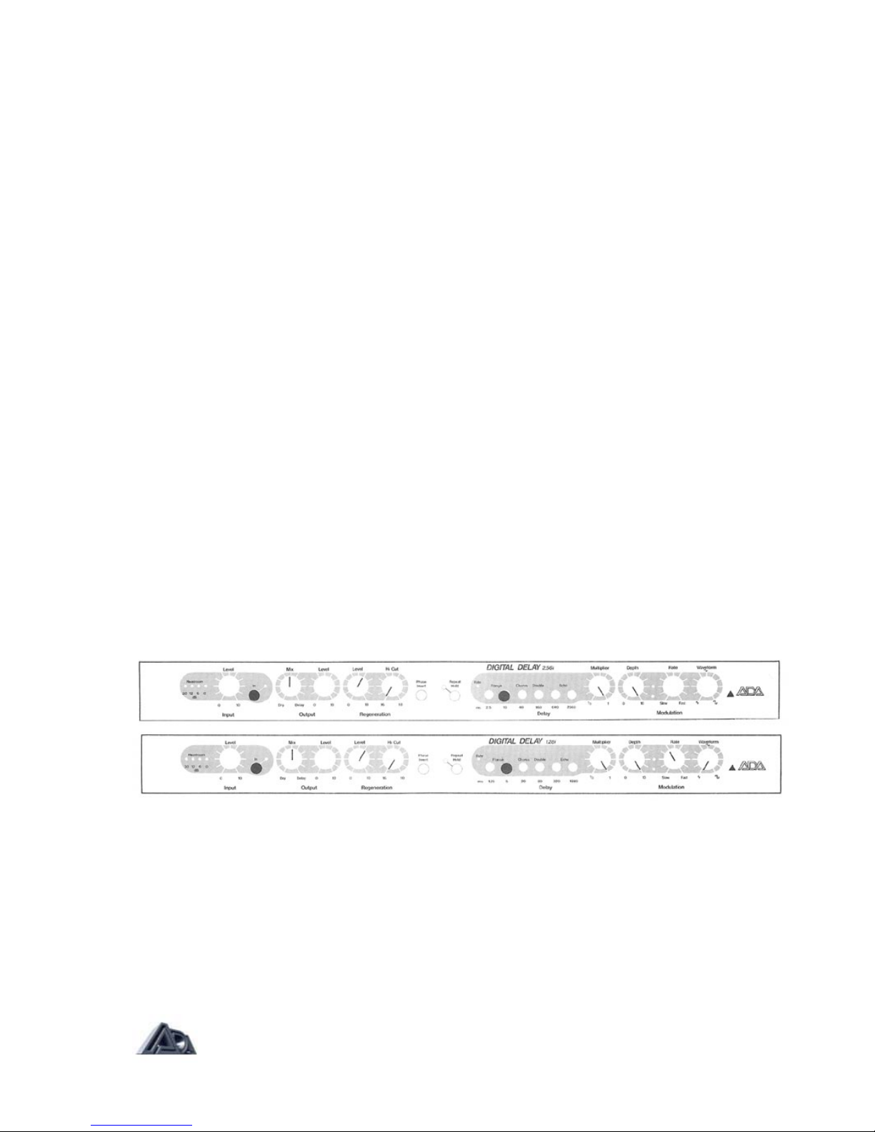
FIGURE 3-1 INITIAL FRONT PANEL SET-UP
3.0 INITIAL SET-UP
ADA DIGITALS interface with a wide variety of input sources including high level
microphones, electronic instruments and mixing consoles. The INPUT circuitry is high
impedance which functions properly with both low or high impedance sources and low (-
10dBV) and high ( + 24dBV) signal levels.
(A) To prepare your DIGITAL DELAY for use, set the rear panel POWER SWITCH to the
"OFF" position. Also set your amplifier's power switch to the "OFF" position.
(B) Connect your DIGITAL DELAY'S AC CORD to a grounded outlet.
(C) Set the front panel controls as shown above (Figure 3-1). ,64i and 2.56i owner's
should use the longest delay factor pushbutton, 640rns and 2560ms respectively.
(D) Connect your signal source to the INPUT jack located on the rear panel.
(E) Connect the EFFECT OUTPUT on your DIGITAL DELAY to your amplifier input or
mixing console effects receive input. The DIRECT OUTPUT is used with a second
amplifier for stereo effects.
Page 4 of 11

ADA 64i-1.28i-2.56i owners manual
(F) Select the "ON" position of the rear panel POWER SWITCH (the TRIANGLE LED
should now be lit), then set your amplifier's power switch to the "ON" position.
(G) Engage the EFFECT IN pushbutton. Your DIGITAL DELAY is now ready for
operation.
3.1 INPUT/OUTPUT ADJUSTMENT
(A) The 4-step HEADROOM LED Meter provides accurate monitoring of the input signal
level relative to the clipping level. To properly set the input level: find the strongest
signal or musical passage that you will put into your DIGITAL DELAY, and set the
INPUT LEVEL control to just barely light the red "0dB" HEADROOM LED. The LED
should flicker only on the strongest signals or notes Never set the INPUT LEVEL
control so the "0dB" LED is constantly on.
Note that the HEADROOM LED Meter monitors, all Signals entering the delay line.
The REGENERATION LEVEL control may effect the headroom and therefore the
readings. While performing, always remember to monitor the HEADROOM LED
Meter for possible overloads.
(B) The OUTPUT MIX control mixes the processed signal with the dry input signal. For
use with instruments, the control will most often be in its center range. For studio
applications where your DIGITAL DELAY is in an effects loop, the MIX control is most
useful in the full clockwise, "DELAY", position. The processed signal level (and thus the
dry/effect mix) is now controlled at the console.
(C) The OUTPUT LEVEL control sets the level of the EFFECT OUTPUT whether in
bypass or effect "IN" mode. In general, guitar level signals will have the control in its mid-
scale or higher, line level signals will generally require positioning the control more
counter-clockwise.
Remember, proper setting of the INPUT/OUTPUT LEVEL controls is necessary to achieve
maximum performance with the least amount of noise and distortion.
3.2 REMOTE FUNCTIONS
EFFECTS BYPASS and REPEAT HOLD are remotely controllable via the rear panel jack
labeled REMOTE. The REMOTE jack accepts a standard ¼” stereo cord (tip-ring-sleeve).
The stereo cord connects with two momentary footswitches. In the EFFECT BYPASS mode,
the input signal source is routed to the EFFECT OUTPUT. BYPASS is actuated by a
momentary closure which grounds the tip to the sleeve. The REPEAT HOLD function allows
non-deteriorating repeat of any source stored in the delay memory. REPEAT HOLD is
actuated by a momentary closure which grounds the ring to the sleeve.
Note that the front panel switches may also be used while the dual footswitch is connected
3.3 REGENERATION SECTION
As the REGENERATION LEVEL control is turned clockwise, more of the delayed audio
signal is sent back to the input of your DIGITAL DELAY. When using short delay settings,
from 0.15 to 40ms, the REGENERATION LEVEL control adds emphasis or resonance to
flanging and chorusing. At longer time delays, from 80 to 2560ms the REGENERATION
LEVEL control adds repeat echos extending to 50 seconds or more.
Room ambience or naturally reflected sounds are quite different from the original signal
because reflective surfaces of a room absorb high frequencies more quickly than low
frequencies. ADA DIGITALS can simulate room acoustics by rolling-off the higher
frequencies with the continuously variable REGENERATION HI-CUT control. At minimum cut
(16kHz), the delayed signal is not altered. In the maximum cut position (1.0kHz), all
Page 5 of 11

ADA 64i-1.28i-2.56i owners manual
regenerated signal content above the mid-range frequencies is attenuated to simulate highly
damped room acoustics. The frequency spectrum of the sound source generally decays as it
would in a natural environment.
3.4 PHASE
The delayed signal's phase is inverted when the PHASE pushbutton is engaged. "Inverted phase"
may correct phasing problems in mixing consoles, or alter the tonal characteristics of short delay
effects such as resonant flanging and doppler chorusing.
3.5 REPEAT HOLD
When engaged, the REPEAT HOLD pushbutton will capture and repeat the signal stored in memory
indefinitely without any loss of audio quality. Up to 2560ms (on the 2.561) of a musical passage may
be repeated as a counterpoint or a background rhythm.
When your DIGITAL DELAY is initially powered up, an internal protection circuit switches the REPEAT
HOLD function out to prevent "howling."
3.6 DELAY SECTION
The DELAY MULTIPLIER control allows continuous 0.125X to 1X adjustment of the delay time
selected from any one of the interlocking DELAY range pushbuttons. The ranges of each of the
DELAY pushbuttons are as follows:
FIGURE 3-2
.64 DELAY TIME RANGES
Left to right
PUSHBUTTON
DELAY TIME (in ms)
MIN MAX
EFFECT
#1
#2
#3
#4
#5
.31 to 2.5
1.25 to 10
5 to 40
20 to 160
80 to 640
Hi Flange
Lo Flange
Chorus
Double/Echo
Echo
FIGURE 3-4
1.28i DELAY TIME RANGES
Left to right
PUSHBUTTON
DELAY TIME (in ms)
MIN MAX
EFFECT
#1
#2
#3
#4
#5
#6
.15 to 1.25
.62 to 5
2.5 to 20
10 to 80
40 to 320
160 to 1280
Hi Flange
Lo Flange
Chorus
Chorus/Dbl.
Double/Echo
Echo
FIGURE 3-4
2.56i DELAY TIME RANGES
Left to right
PUSHBUTTON
DELAY TIME (in ms)
MIN MAX
EFFECT
#1
#2
#3
#4
#5
#6
.31 to 2.5
1.25 to 10
5 to 40
20 to 160
80 to 640
320 to 2650
Hi Flange
Lo Flange
Chorus
Double/Echo
Echo
Long Echo
Page 6 of 11
ADA 64i-1.28i-2.56i owners manual
3.7 MODULATION
The MODULATION DEPTH control allows you to fade between the static setting of the DELAY
MULTIPLIER control and the sweeping voltage of the internal low frequency oscillator. When the
DEPTH control is set at "0", the delayed signal is not swept and the delay time remains
stationary.
As the DEPTH control is turned clockwise, a wider range of the selected time delay is swept. With the
DEPTH control set at " 1 0", the full 8: 1 range is swept and the MULTIPLIER control is disabled. At
settings less than "10", the MULTIPLIER sets the center of the sweep range. The MODULATION
RATE LEDS give a visual indication of the sweep speed, the direction the sweep is moving (up or
down), and how close the sweep is to its upper or lower limits. The RATE LEDS increase in brightness
as they reach their upper or lower limits, giving a visual indication of the point where your effect is
starting to "turn around."
The MODULATION WAVEFORM control continuously blends the shape of the modulation function
from a triangle to a sine to a square wave. Full counterclockwise position of the knob selects a triangle
wave for delay times that reach a peak or dip and quickly turnaround — especially useful for flanging
effects. Advancing the knob towards the 12 o'clock position selects pure sine wave modulation for
delay times that smoothly increase and decrease at a speed corresponding to the RATE control,
useful for chorusing and vibrato effects. Full clockwise position selects a square wave for delay times
that jump up, then down, for stepped pitch-shifting effects. The MODULATION SPEED control adjusts
the low frequency oscillator from (Msec to 25sec. Extremely slow sweeps are useful for chorusing,
flanging and subtle effects. Faster sweeps can produce vibrato, fast flanging and rotating speaker
simulation.
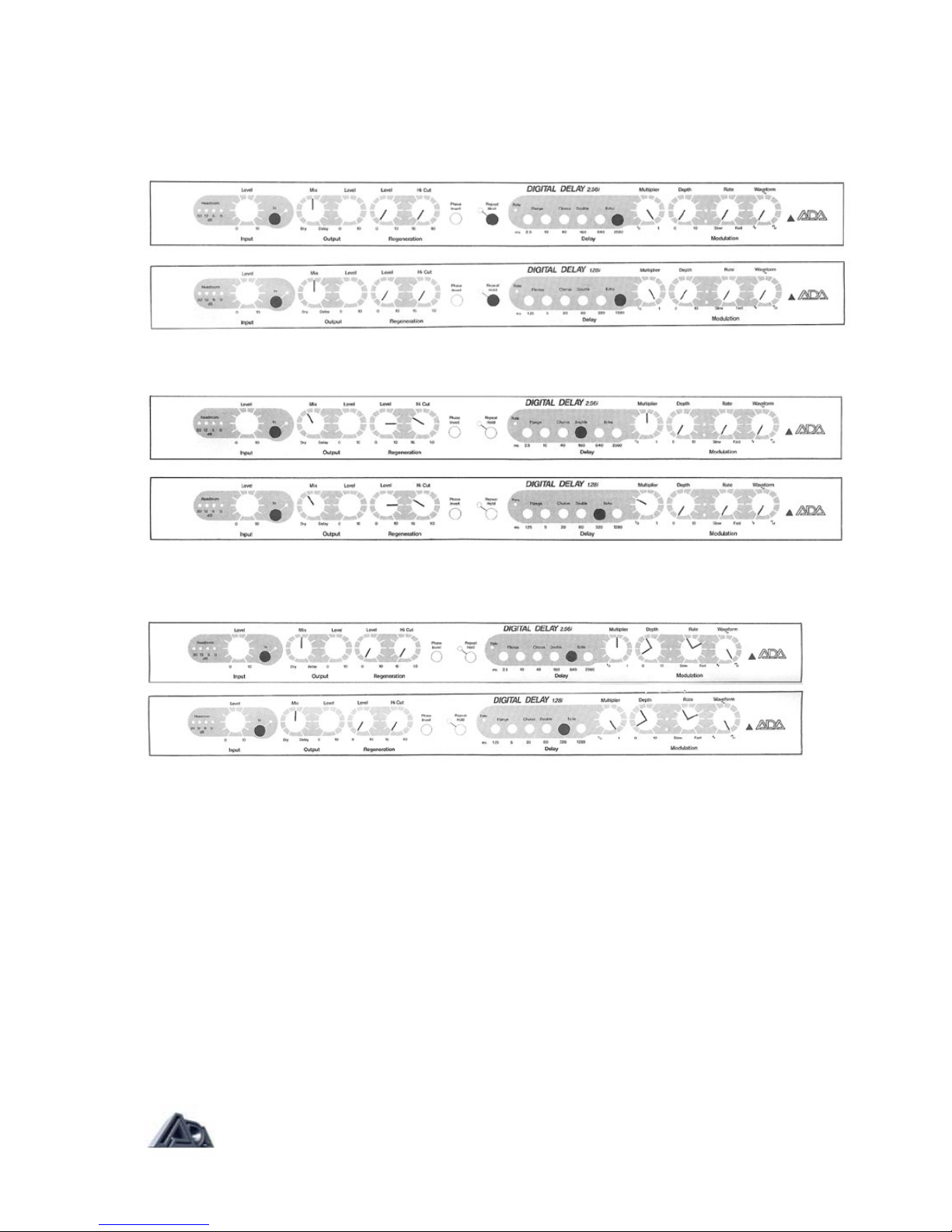
4.0 PATCH DIAGRAMS
IMPORTANT NOTICE:
.64i OWNERS SHOULD USE DIAGRAMS OF 2.561 TO SET FRONT PANEL CONTROLS,
AS THE FIRST FIVE DELAY PUSHBUTTONS ON THE 2.561 ARE IDENTICAL TO THE
THOSE ON THE .64
FIGURE 4-1 / CLASSIC FLANGE
This demonstrates the full 8:1 sweep range of your digital delay. Turning the REGENERATION LEVEL
control clockwise produces more resonant or more dramatic flanging effects.
FIGURE 4-2 / EVEN/ODD HARMONIC
At minimum MULTIPLIER control settings, switch between in-phase and out-of-phase settings with the
PHASE switch. Inverted signals will cancel lower-frequencies thereby apparently emphasizing treble
content.
Page 7 of 11

ADA 64i-1.28i-2.56i owners manual
FIGURE 4-3 / THICK CHORUS
This is a dramatic, very deep chorus. Adjust the SPEED control for the desired effect.
FIGURE 4-4 / STEREO DOUBLING
The OUTPUT MIX control is set at full delay (10) for double tracking when using the DIRECT OUTPUT
and the EFFECT OUTPUT in a stereo PA or recording system. In mono systems, set the OUTPUT
MIX control in its center position (5). A single short repeat of the note or chord is produced for added
thickness.
FIGURE 4-5 / REPEAT ECHO
By carefully adjusting the REGENERATION LEVEL control, you can select from one repeat to multiple
repeats lasting 30 seconds or more. Vary the HI-CUT control to further modify the repeat echo by
taking the "edge" off of percussive signals.
Page 8 of 11
ADA 64i-1.28i-2.56i owners manual
FIGURE 4-6 /REPEAT HOLD
This captures, stores, and repeats a segment of sound without signal degradation. The pitch and
repeat rate may be modified by using the DELAY MULTIPLIER control. Many useful special effects
can be produced by varying the MODULATION DEPTH and SPEED controls.
FIGURE 4-7 / REVERB
Mixing a higher percentage of dry signal will position the reverb further into the background.
FIGURE 4-8 / STEPPED PITCH-SHIFTING
This produces a "stepped" pitch-shifting as the delay time jumps up, then down, according to the SWEEP
RATE setting. Wider pitch intervals can be produced by increasing the DEPTH setting.
Page 9 of 11

ADA 64i-1.28i-2.56i owners manual
4.1 BLANK PATCH SHEETS
Notes:
Notes:
Notes:
Notes:
Notes:
Notes:
Notes:
Page 10 of 11
ADA 64i-1.28i-2.56i owners manual
Page 11 of 11
5.0 SPECIFICATIONS
DYNAMIC RANGE 90dB
BANDWIDTH, DRY 10Hz to 20kHz
DELAY 20Hzto16kHz
DISTORTION (THD) @ 1 kHz dry, 0dBV, 0.5% max.
wet, 0dBV, 1.0% max.
dry, +4dBV, 0.65% max.
wet, +4dBV, 1.2% max.
DELAY RANGE .64i — 0.31 to 640ms
1.28i — 0.15 to 1280ms
2.56i — 0.31 to 2560ms
MODULATION DEPTH 0 (none) to 8:1
SWEEP SPEED 0.1 sec to 25sec
INPUT 510k ohm single-ended, ¼” phone jack, handles
instrument and single-ended line-level signals.
OUTPUT(S) Single-ended, ¼” phone jacks, drives 600 ohms.
MAX. INPUT LEVEL +20dBV (ref. .775VRMS)
MAX. OUTPUT +20dBM (ref. 775VRMS)
REMOTE SWITCH LOGIC Grounding terminal engages.
POWER CONSUMPTION 20 watts
POWER 120 VAC, 50/60HZ
DIMENSIONS L-10.5" x W-19" x H-1.75" (483 x 44 x 269mm)
WEIGHT 6.5lbs (14.33kg); 10lbs (22kg) shipping
OPTION 220 or 240 VAC 50/60Hz
ACCESSORY FS-2 DUAL FOOTSWITCH (with ¼” STEREO CORD)
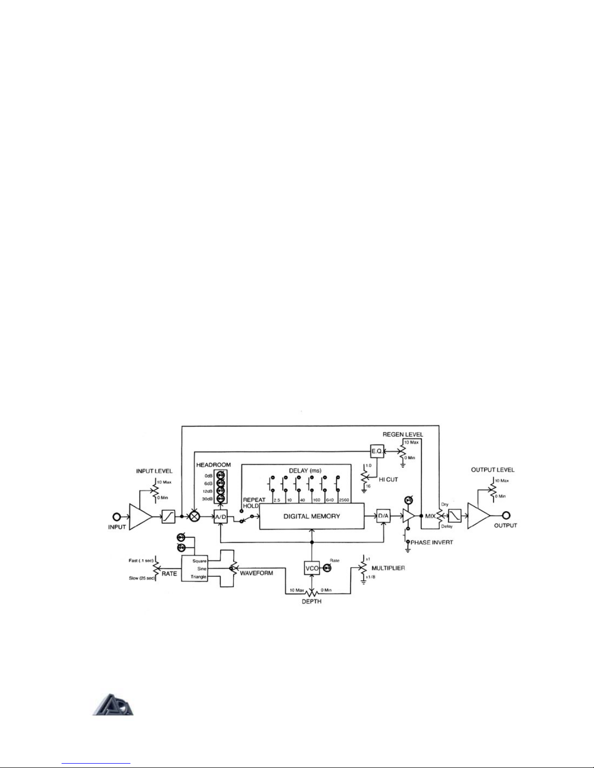
6.0 BLOCK DIAGRAM
This manual suits for next models
2
Table of contents
Other A/DA Recording Equipment manuals


