Thank you for choosing a Free The Tone product.
In order to take full advantage of the features and performance it provides, please read this owner’s manual thoroughly, and keep it
in a safe place for future reference.
Table of Contents
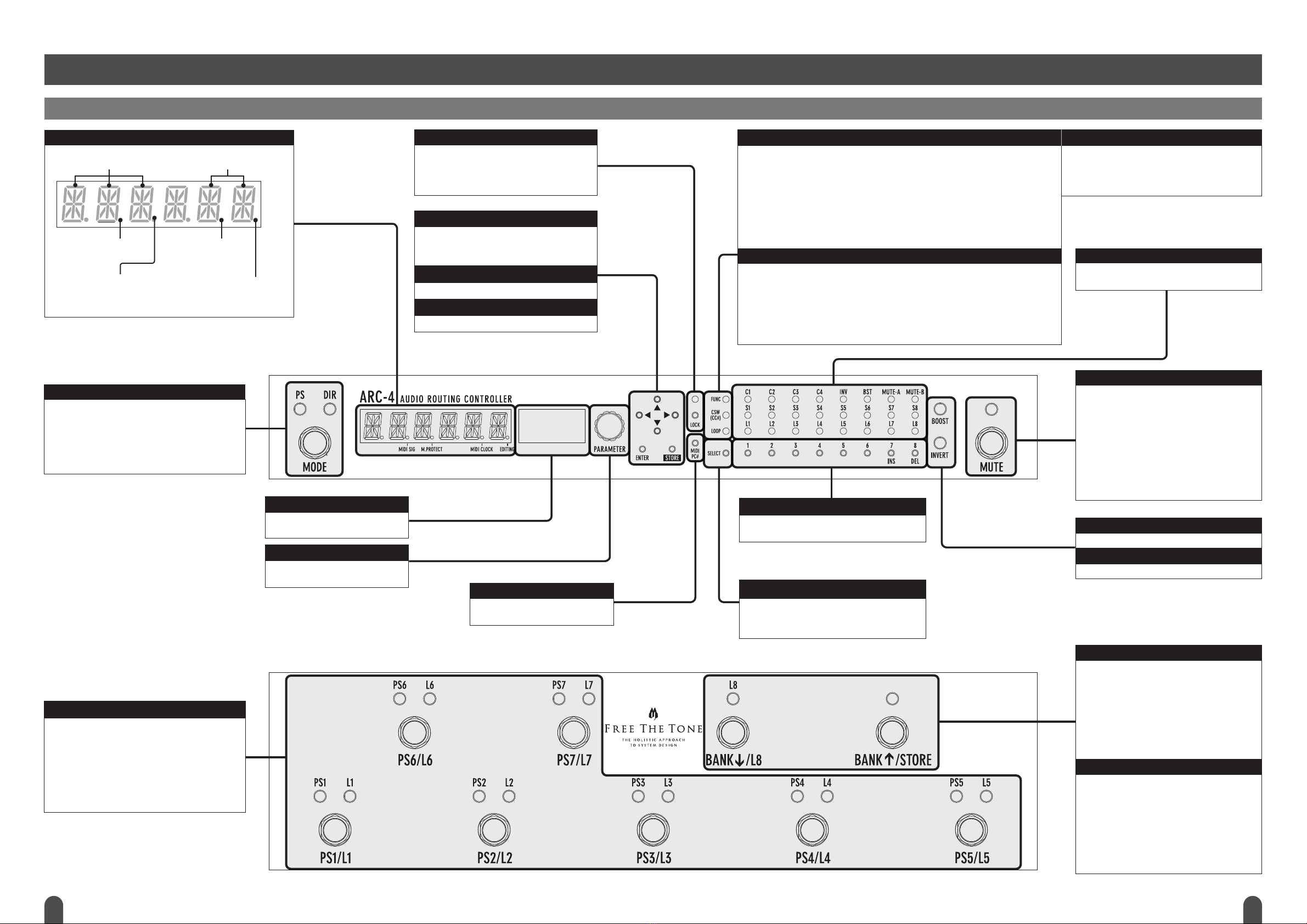
Controls and Indicators .................................................................................................................................................................. 4
Front Panel ........................................................................................................................................................................... 4
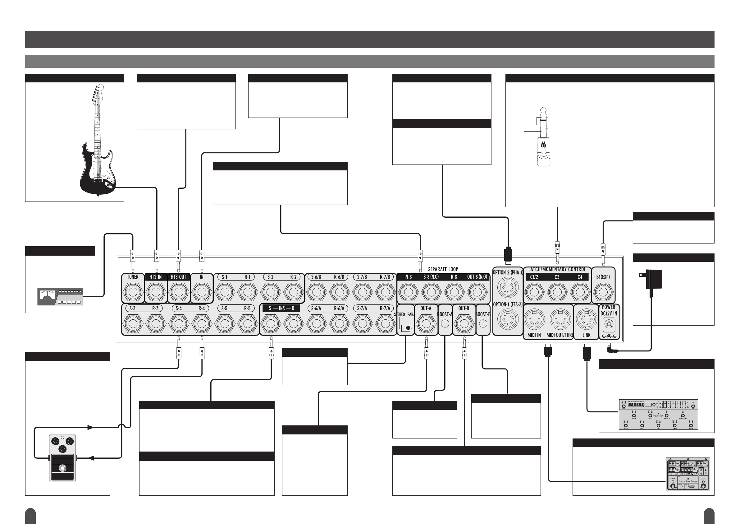
Rear Panel ........................................................................................................................................................................... 6
Terminals in Detail ................................................................................................................................................................... 8
Block Diagram ........................................................................................................................................................................... 8
Signal Flow .............................................................................................................................................................................. 9
How to Store/Recall Effect Loop Combinations or Various Functions (Preset Mode) ................................................................................................... 9
Organization of Presets .............................................................................................................................................................. 9
Managing Presets ................................................................................................................................................................... 10
Switching between Preset and Direct Modes ....................................................................................................................................... 10
Storing an Effect Loop Combination ................................................................................................................................................ 10
Recalling a Preset ................................................................................................................................................................... 10
Storing Phase Invert Function (INVERT) Setting in a Preset ........................................................................................................................ 10
Storing Boost Function Setting in a Preset .......................................................................................................................................... 10
Storing Mute (MUTE-A, MUTE-B) Setting in a Preset .............................................................................................................................. 10
How to Control External Devices from ARC-4 (Preset Mode) .......................................................................................................................... 11
Storing Control Terminal Setting in a Preset ........................................................................................................................................ 11
Storing MIDI Program Change Number Transmission in a Preset .................................................................................................................. 11
Storing MIDI Control Change Number Transmission in a Preset .................................................................................................................... 11
Setting MIDI Control Change Number to be Sent (Preset Mode) ................................................................................................................... 12
How to Perform Detailed Settings of ARC-4 (Edit Mode) .............................................................................................................................. 12
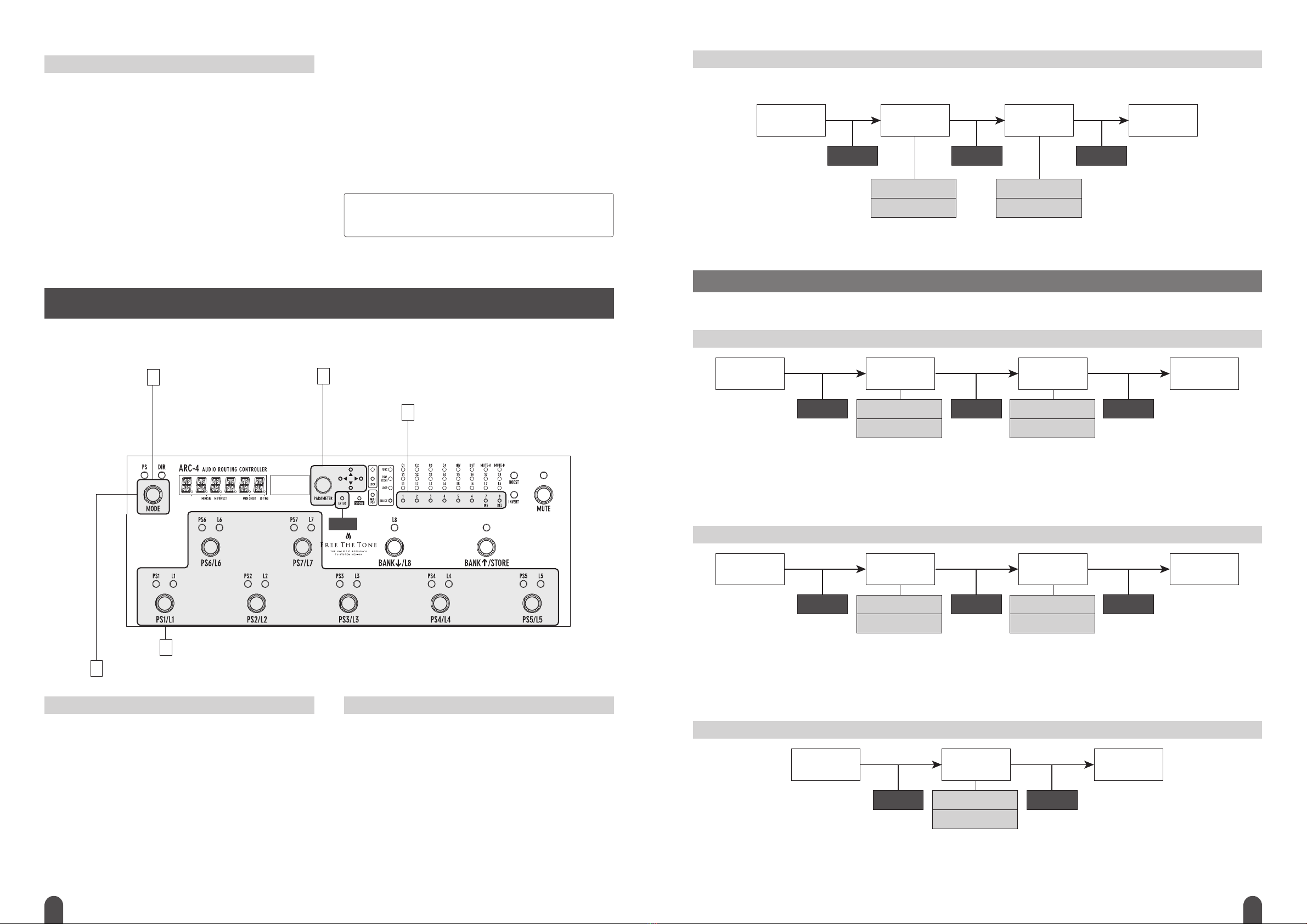
Basic Operation ..................................................................................................................................................................... 12
PS/L Switch Menus ................................................................................................................................................................. 12
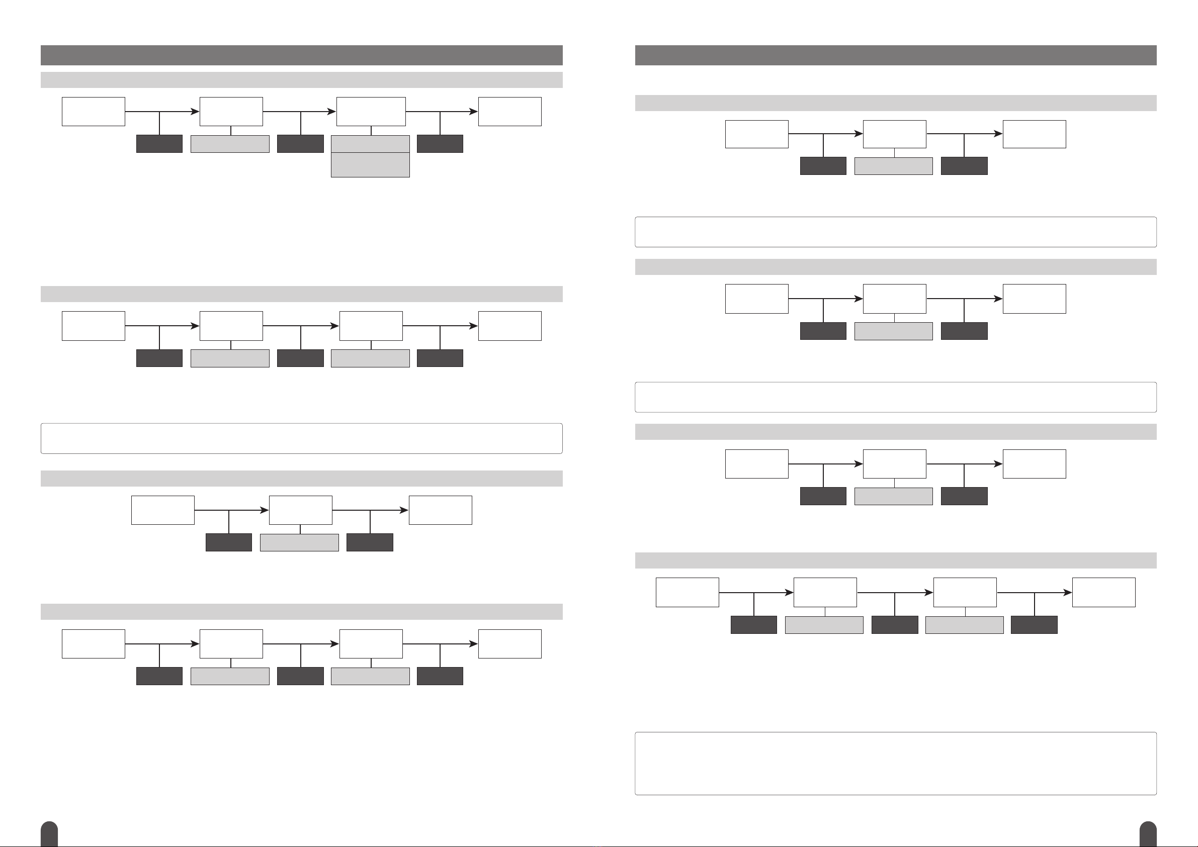
Screens Displayed in Edit Menu Operation and Flow of Setup Operation ........................................................................................................... 13
PRESET ................................................................................................................................................................................ 13
Copying Presets (PS-CP): ON/OFF switch 1 ....................................................................................................................................... 13
Copying Banks (BK-CP): ON/OFF switch 2 ......................................................................................................................................... 13
Deleting Presets (PS-DL): ON/OFF switch 3 ....................................................................................................................................... 13
Deleting Banks (BK-DL): ON/OFF switch 4 ......................................................................................................................................... 14
Switching Preset Contents (PS-SW): ON/OFF switch 5 ............................................................................................................................ 14
Switching Bank Contents (BK-SW): ON/OFF switch 6 ............................................................................................................................. 14
TITLE ................................................................................................................................................................................... 14
Setting Preset Titles (PS-TT): ON/OFF switch 1 .................................................................................................................................... 14
Setting Bank Titles (BK-TT): ON/OFF switch 2 ..................................................................................................................................... 15
Setting MIDI Channel Name (MD-TT): ON/OFF switch 3 ........................................................................................................................... 15
Setting Duration in which Recalled Preset Title is Being Shown (TT-DP): ON/OFF switch 4 ....................................................................................... 15
SETLIST ................................................................................................................................................................................ 16
Setting Setlists (ST-LS): ON/OFF switch 1 ......................................................................................................................................... 16
Copying Setlists (SL-CP): ON/OFF switch 2 ........................................................................................................................................ 16
Deleting Setlists (SL-DL): ON/OFF switch 3 ........................................................................................................................................ 16
Switching Setlist Contents (SL-SW): ON/OFF switch 4 ............................................................................................................................. 16
MIDI .................................................................................................................................................................................... 17
Setting MIDI Receive Channels (RX-CH): ON/OFF switch 1 ........................................................................................................................ 17
Setting MIDI Transmit Channels (TX-CH): ON/OFF switch 2 ....................................................................................................................... 17
Setting Expression Pedal’s MIDI Transmit Channel (EP-CH): ON/OFF switch 3 .................................................................................................... 17
Setting MIDI Control Change Number to Each Function (CC-NM): ON/OFF switch 4 .............................................................................................. 17
Setting whether to Transmit Each Function’s MIDI Control Change Number when Presets are Switched (CC-TX): ON/OFF switch 5 ............................................. 18
Handling Precautions
• Never connect or disconnect plugs to/from the input/output terminals on the ARC-4 when the external device that drives speakers is powered. Doing so can cause noises and
damage the speakers.
• Avoid applying excessive force to the footswitches, tact switches, and phone jacks on the ARC-4.
• If the unit malfunctions or behaves erratically, cease operation at once and contact your local dealer or Free The Tone directly.
2 3
Showing Bank Title on 12-DIGIT LED DISPLAY/LDP-1 (option) (EX-DP): ON/OFF switch 6 ....................................................................................... 18
Setting MIDI OUT/THRU Terminal (OT/TH): ON/OFF switch 7 ..................................................................................................................... 18
Setting MIDI Program Change Number’s Start Number: ON/OFF switch 8 ........................................................................................................ 18
CSW/TAP .............................................................................................................................................................................. 19
Setting MIDI Control Change Number to be Sent using CSW Switch (CS-CC): ON/OFF switch 1 ................................................................................. 19
Setting Operation Type of CSW Switch (CS-TP): ON/OFF switch 2 ................................................................................................................ 19
Setting Footswitch Assigned to TAP Tempo Input (TP-FS): ON/OFF switch 3 ..................................................................................................... 19
Setting Operation Type of MIDI Clock (MD-CK): ON/OFF switch 4 ................................................................................................................ 20
Setting whether to Output TAP Information or Not (TP-DT): ON/OFF switch 5 .................................................................................................... 20
SETUP ................................................................................................................................................................................. 20
Setting Operation Mode when Two ARC-4 Units are Connected with Dedicated Link Cable (LK-MD): ON/OFF switch 1 ........................................................ 20
Setting Initial Operation Mode when ARC-4 is Powered On (OP-MD): ON/OFF switch 2 ......................................................................................... 20
Setting Function to be Assigned to EFS-3 Connected to OPTION-1 (EFS-3) Terminal and PS/L Switch on ARC-4 (FS-AS): ON/OFF switch 3 ................................. 21
Setting Operation Type of Control Signal to be Sent (RL-CT): ON/OFF switch 4 .................................................................................................. 21
Setting Operation Type of MUTE Switch (MT-MD): ON/OFF switch 5 ............................................................................................................. 21
Selecting Mute Circuit to be Activated when MUTE Switch is Turned On (MT-PT): ON/OFF switch 6 ............................................................................ 22
Selecting Control Terminal to be Activated Simultaneously when MUTE Switch is Pressed (MT-LK): ON/OFF switch 7 ......................................................... 22
Setting Operation when Same PS/L Switch is Pressed (SC-PS): ON/OFF switch 8 .............................................................................................. 22
UTILITY ................................................................................................................................................................................ 22
Locking Out Setting Changes from Front Panel (AT-LC): ON/OFF switch 1 ....................................................................................................... 22
Protecting Memory Contents from Change (MM-PR): ON/OFF switch 2 .......................................................................................................... 23
Adjusting LED Brightness (LD-BR): ON/OFF switch 3 ............................................................................................................................. 23
Setting Expression Pedal’s Calibration (EP-CB): ON/OFF switch 4 ............................................................................................................... 23
Receiving ARC-4’s Data (DP-LD): ON/OFF switch 5 .............................................................................................................................. 23
Sending ARC-4’s Data (DP-LD): ON/OFF switch 5 ................................................................................................................................. 24
Initializing to Factory Reset Status (INITI): ON/OFF switch 6 ....................................................................................................................... 24
Updating Firmware via MIDI (FW-UD): ON/OFF switch 7 ........................................................................................................................... 24
Using ARC-4 Efficiently ............................................................................................................................................................... 25
Connection Examples .............................................................................................................................................................. 25
Basic Connection ............................................................................................................................................................... 25
Using Two Guitars Separately ................................................................................................................................................... 25
Switching between Two Amplifiers ............................................................................................................................................. 25
Switching between Two Amplifiers or Using Two Amplifiers Simultaneously ................................................................................................... 26
Leaving Delay Sound when MUTE Switch is Pressed .......................................................................................................................... 26
Connecting a Fuzz or Wah-wah Pedal .......................................................................................................................................... 26
Connecting a Device to be Controlled Directly to Insert Terminal ............................................................................................................... 27
Using L6 and L7 as Stereo Loops .............................................................................................................................................. 27
Further Connection Examples ...................................................................................................................................................... 28
Using LB-2 to Add Loops (1) .................................................................................................................................................... 28
Using LB-2 to Add Loops (2) ................................................................................................................................................... 28
Using LB-2 to Add Loops to Amplifier Send/Return ............................................................................................................................ 29
Details of MIDI Data Sent When CSW is Turned On/Off .............................................................................................................................. 29
Details of ON/OFF and SELECT Switches ............................................................................................................................................. 29
ARC-4’s Bank Presets and MIDI Program Change Numbers ......................................................................................................................... 30
Main Specifications/Ratings .......................................................................................................................................................... 31
Safety Precautions .................................................................................................................................................................... 31