A.H. Systems SAS-585 User manual

A.H. Systems SAS-585 Standard Gain Horn Antenna
© A.H. Systems inc. – June 2014
REV A
1
SAS-585
Standard Gain Horn
Operation Manual

A.H. Systems SAS-585 Standard Gain Horn Antenna
© A.H. Systems inc. – June 2014
REV A
2
TABLE OF CONTENTS
INTRODUCTION
Introduction ................................................................................................................ 3
Intended Purposes...................................................................................................... 4
Optional Equipment .................................................................................................... 5
OPERATING INSTRUCTIONS
Assembly Instructions ................................................................................................ 6
Mounting Instructions.................................................................................................. 6
Operating Instructions................................................................................................. 6
SPECIFICATIONS
Specifications ............................................................................................................. 8
Typical Data ................................................................................................................ 9
Calculations .............................................................................................................. 11
Convertion Factors.................................................................................................... 12
MAINTENANCE
Maintenance Procedures ......................................................................................... 13
Annual Calibration..................................................................................................... 13
Warranty ................................................................................................................... 14

A.H. Systems SAS-585 Standard Gain Horn Antenna
© A.H. Systems inc. – June 2014
REV A
3
INTRODUCTION
The SAS-585 Standard Gain Horn Antenna is designed specifically for utilization in
emissions and immunity testing over the frequency range of 8.2 GHz to 12.4 GHz.
This X-band horn antenna is linearly polarized and has medium gain, low VSWR,
and a constant antenna factor. The antenna performance is very precise and
predictable through design parameters and comparisons of measured versus
computed antenna factors and gain have been shown to be +/- 0.5 dB. Therefore,
this horn antenna is considered to be a standard reference, similar to that of a
resonant dipole below 1 GHz. The coax-to-waveguide adapter is the only power-
limiting component on the antenna and can be removed if high fields are desired.
GENERAL DESCRIPTION
The SAS-585 Standard Gain Horn Antenna mounts directly to the tripod azimuth
and elevation head (AEH-510) at the bottom of the antenna. Horizontal and vertical
polarization is obtained by rotating the antenna on the tripod. The azimuth and
elevation head also allows the operator to vary the antenna azimuth (left right
direction) and elevation (up, down direction) and makes it easy to change the
antenna polarity (horizontal or vertical).
To obtain the field strength of the signal being measured, the operator must add the
receiver reading in dBuV, the antenna factor in dB, and the cable attenuation in dB.
This yields the field strength in dBuV/m. Calibrations for the E-field antennas are
supplied at 1 meter.

A.H. Systems SAS-585 Standard Gain Horn Antenna
© A.H. Systems inc. – June 2014
REV A
4
INTENDED PURPOSES
The standard gain horn antenna is intended for general laboratory use in a wide
variety of industrial and scientific applications. It has been designed to be used
in the process of generating, controlling and measuring high levels of
electromagnetic Radio Frequency (RF) energy. It is the responsibility of the user
to assure that the device is operated in a location which will control the radiated
energy such that it will not cause injury and will not violate regulatory levels of
electromagnetic interference.

A.H. Systems SAS-585 Standard Gain Horn Antenna
© A.H. Systems inc. – June 2014
REV A
5
OPTIONAL EQUIPMENT
The following is a recommend accessory list for the SAS-585 Standard Gain Horn
Antenna:
CONNECTING ACCESSORIES:
PAM-0118
This preamplifier has a broad frequency range and high gain, designed to match
the double ridge guide horn antenna. An ideal solution for improving overall system
sensitivity.
SAC-18G-3
Our Low-Loss High-Frequency flexible cables are the preferred choice over
standard cable types. With improved power handling, low VSWR, and high
frequency capabilities, the Low-Loss cables can be made to your specified length
MOUNTING ACCESSORIES:
AEH-510
Azimuth and elevation head is used to assist the test engineer in orientating the
horn antenna towards the device under test.
ATU-510
Each tripod leg is independently adjustable in angle and length to facilitate
antenna height setting. The tripod legs have a rubber tip on one end for indoor or
hard surface use, and a metal spike on the other end for outdoor soft surface
(such as dirt) use.
ATU-514
This collapsible tripod is built with all non-metallic materials that will not influence
your antenna measurements. The ATU-514 is a no-nonsense antenna tripod that
offers up to 50lbs. (22.6Kg) load capacity and has telescoping legs with an
adjustable center mast to achieve heights up to 2 meters.

A.H. Systems SAS-585 Standard Gain Horn Antenna
© A.H. Systems inc. – June 2014
REV A
6
OPERATING INSTRUCTIONS
ASSEMBLY INSTRUCTIONS
There is no assembly required, the SAS-585 Horn antenna is supplied with an
attached waveguide to coax adapter and tripod mount.
MOUNTING INSTRUCTIONS
The antenna should be firmly mounted to a tripod with a 1/4-20 male stud.
Horizontal polarization can be determined by the orientation of the RF connector. If
the connector is parallel (or horizontal) to the ground, then the antenna is in the
horizontal polarization. If the antenna is perpendicular to the ground the antenna is
in the vertical polarization.
The cable connecting the Horn antenna to the receiver must have 50
characteristic impedance and matching cable connectors. The cable must be well
shielded since any leakage will cause erroneous readings. For emissions testing,
an optional preamplifier is recommended to help increase system sensitivity.
The SAS-585 horn antenna has a beamwidth of approximately 30 degrees and it
should be pointed or aimed in the direction that the received signal is coming from.
Refer to our antenna beamwidth coverage tool on our website
(https://www.ahsystems.com/EMC-formulas-equations/Antenna-beamwidth-
coverage-calculation.php). The measurement reference point is at the aperture of
the antenna for all distances.

A.H. Systems SAS-585 Standard Gain Horn Antenna
© A.H. Systems inc. – June 2014
REV A
7
OPERATING INSTRUCTIONS
Once the antenna is mounted to a mast or tripod, connect a N-type coaxial cable
from the horn antenna to a receiver or RF generator. The cable should be matched
to 50 ohms, and it is recommended to use a high-frequency low-loss cable (i.e.,
SAC-18G-3 Low Loss cable). For certain applications where an increased dynamic
range is required, an optional preamplifier (PAM-0118P) may be used to increase
the total system sensitivity.
CAUTION: Even though the horn antenna does not
have any ESD concerns, touching the horn antenna
while connected to a sensitive preamplifier may cause
damage to that device.
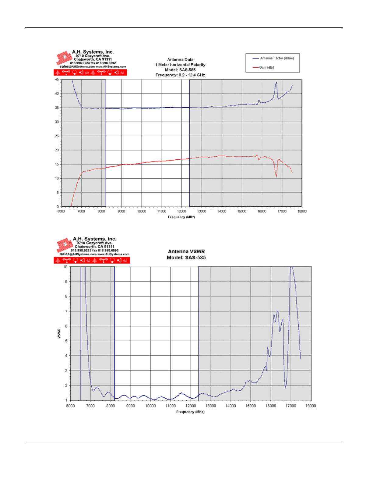
The antenna factor is used to convert the receiver reading to field intensity. In
measuring the field intensity with the standard gain horn antenna, add the antenna
factor to the receiver reading (dBuV). The antenna factor supplied with each antenna
is individually calibrated at 1 Meter using the three-antenna technique per ARP-958.
The 1-meter measurement point is measured from the aperture of the antenna.
ADDITIONAL NOTES
These waveguide horn antennas will respond well beyond their specified frequency
ranges. The operational range of the waveguides themselves dictates the specified
frequency range of the antennas.
The coax-to-waveguide adapter is the only power-limiting component on the
antenna and can be removed if high fields are desired.
As mentioned before, the standard gain horn antenna has an approximate 15 dB
gain with a 30-degree beamwidth. Other horn antennas are available with different
apertures and flare angles that will increase or decrease the gain of the antenna. As
the gain increases, the beamwidth will decrease. Call us with your specification and
discuss your needs with one of our design engineers.

A.H. Systems SAS-585 Standard Gain Horn Antenna
© A.H. Systems inc. – June 2014
REV A
8
SPECIFICATIONS
The SAS-585 Horn Antenna specifications:
ELECTRICAL
Frequency Range ..................................................................... 8.2 GHz – 12.4 GHz
Antenna Factor .......................................................................................... 34.6 dB/m
Average Gain ................................................................................................15.6 dBi
Maximum Continuous Power......................................................................250 Watts
Maximum Radiated Field: ............................................................................ 500 V/m
Average Beamwidth (E-Field)............................................................................... 30
Average Beamwidth (H-Field) .............................................................................. 30
Impedance (nominal) .......................................................................................... 50
Average VSWR................................................................................1.3:1 (1.5:1 max)
Connector: ........................................................................WR-90 to N-type (female)
MECHANICAL
Length ................................................................................................... 7.2” (18.3cm)
Width....................................................................................................... 2.1” (5.3cm)
Height...................................................................................................... 2.8” (7.1cm)
Weight ..............................................................................................0.6 lbs. (0.27 Kg)
Figure 1 – SAS-585 (Horizontal Polarization)

A.H. Systems SAS-585 Standard Gain Horn Antenna
© A.H. Systems inc. – June 2014
REV A
9
TYPICAL DATA

A.H. Systems SAS-585 Standard Gain Horn Antenna
© A.H. Systems inc. – June 2014
REV A
10
CALCULATIONS
EMISSIONS TESTING
Individual calibration data for the SAS-585 horn antenna is supplied at a 1-meter
separation distance. For emissions measurements, add the antenna factor plus
cable loss to receiver reading in dBV to convert to field strength in dBV/meter.
Field Strength(dBuV/m) = SA(dBuV) + AF(dB/m) + cable loss (dB)
SA = Spectrum Analyzer or Receiver voltage reading
AF = Antenna Correction Factor
CL = Cable Loss in dB
IMMUNITY TESTING
For Immunity measurements (typically 1 meter), the generated electric field
strength can be calculated by:
FS = Approximate Field Strength in (V/m)
P = Power in watts
g = Numeric Gain
d = Distance in meters

A.H. Systems SAS-585 Standard Gain Horn Antenna
© A.H. Systems inc. – June 2014
REV A
11
TYPICAL CONVERSION FORMULAS
LOG -> LINEAR VOLTAGE
FIELD STRENGTH & POWER DENSITY
dBV to Volts
V = 10 ((dBV – 120) / 20)
dBV/m to V/m
V/m = 10 (((dBV/m) -120) / 20)
Volts to dBV
dBV = 20 log(V) + 120
V/m to dBV/m
dBV/m = 20 log(V/m) + 120
dBV to Volts
V = 10 (dBV / 20)
dBV/m to dBmW/m2
dBmW/m2 = dBV/m – 115.8
Volts to dBV
dBV = 20log(V)
dBmW/m2 to dBV/m
dBV/m = dBmW/m2 + 115.8
dBV to dBV
dBV = dBV +120
dBV/m to dBA/m
dBA/m = dBV/m – 51.5
dBV to dBV
dBV = dBV - 120
dBA/m to dBV/m
dBV/m = dBA + 51.5
LOG -> LINEAR CURRENT
dBA/m to dBpT
DBpT = dBA/m + 2
dBA to uA
A = 10 (dBA / 20)
dBpT to dBA/m
dBA/m = dBpT – 2
A to dBA
dBA = 20 log(A)
W/m2 to V/m
V/m = SQRT(W/m2 * 377)
dBA to A
A = 10 (dBA / 20)
V/m to W/m2
W/m2 = (V/m)2 / 377
A to dBA
dBA = 20log(A)
T to A/m
A/m = T / 1.25
dBA to dBA
dBA = dBA + 120
A/m to T
T = 1.25 * A/m
dBA to dBA
dBA = dBA -120
E-FIELD ANTENNAS
LOG -> LINEAR POWER
Correction Factor
dBV/m = dBV + AF
dBm to Watts
W = 10((dBm – 30)/10)
Field Strength
V/m = 30 * watts * Gain numeric
meters
Watts to dBm
dBm = 10log(W) + 30
Required Power
Watts = (V/m * meters)2
30 * Gain numeric
dBW to Watts
W = 10(dBW / 10)
LOOP ANTENNAS
Watts to dBW
dBW = 10log(W)
Correction Factors
dBA/m = dBV + AF
dBW to dBm
dBm = dBW + 30
Assumed E-field for
shielded loops
dBV/m = dBA/m + 51.5
dBm to dBW
dBW = dBm - 30
dBpT = dBV + dBpT/V
TERM CONVERSIONS
dBm to dBV
dBV = dBm + 107 (50)
dB
V = dBm + 10log(Z) + 90
CURRENT PROBES
dBV to dBm
dBm = dBV – 107 (50)
dBm = dB
V – 10log(Z) – 90
Correction Factor
dBA = dBV – dB(ohm)
dBm to dBA
dBA = dBm – 73 (50)
dB
A = dBm – 10log(Z) + 90
Power needed for injection probe given voltage(V) into
50 load and Probe Insertion Loss (IL)
dBA to dBm
dBm = dBA + 73 (50)
dBm = dB
A + 10log(Z) – 90
Watts = 10 ((IL + 10log(V2/50))/10)
dBA to dBV
dBV = dBA + 34 (50)
dB
V = dB
A + 20log(Z)
dBV to dBA
dBA = dBV – 34 (50)
dB
A = dB
V – 20log(Z)

A.H. Systems SAS-585 Standard Gain Horn Antenna
© A.H. Systems inc. – June 2014
REV A
12
MAINTENANCE
MAINTENANCE PROCEDURES
Proper antenna maintenance should include:
•Visual inspection of RF connectors
•Check for loose or missing hardware
•Check for corrosion near the joints
At least once a month it is a good idea to wipe down the antenna with a damp rag.
ANNUAL CALIBRATION
To ensure reliable and repeatable long-term performance, annual re-calibration of
your antennas, preamplifiers and current probes by A.H. Systems experienced
technicians is recommended. Our staff can calibrate almost any type or brand of
antenna.
It is always up to the user to determine the appropriate interval for calibration
certification based on the requirements of the end user’s specific test/application.
The calibration of EMC antennas is important for those conforming to compatibility
standard. Radiated emissions testing for electromagnetic compatibility (EMC)
requires the measurement of electric field (E-field) strength, which is compared
with a limit level. The output voltage of an antenna is converted to E-field strength
via its antenna factor, the measurement of which must include the uncertainty
components related to that particular antenna, taking into consideration the
environment in which the antenna is to be used for the testing. Most standards will
specify the appropriate interval for re-calibration of your EMC antenna.
In some cases, these antennas are used for a manufacturer’s pre-compliance
testing, field monitoring, surveillance and/or other applications where the exact
field intensity of the received signal is not of importance. For those customers a
yearly re-calibration is not necessary, however it is recommended that an interval
for maintenance be performed.
For more information about our calibration services or to place an order for
antenna calibration visit our website at http://www.AHSystems.com
or call 1(818) 998-0223.

A.H. Systems SAS-585 Standard Gain Horn Antenna
© A.H. Systems inc. – June 2014
REV A
13
WARRANTY INFORMATION
A.H. Systems Inc., warrants that our Antennas, Sensors and Probes will be free from
defects in materials and workmanship for a period of three (3) years. All other products
delivered under contract will be warranted for a period of two (2) years. Damage caused
by excessive signals at the product's input is not covered under the warranty. A.H.
Systems' obligation under this warranty shall be limited to repairing or replacing, F.O.B.
Chatsworth, California, each part of the product which is defective, provided that the
buyer gives A.H. Systems notice of such defect within the warranty period commencing
with the delivery of the product by A.H. Systems.
The remedy set forth herein shall be the only remedy available to the buyer, and in no
event shall A.H. Systems be liable for direct, indirect, incidental or consequential
damages.
This warranty shall not apply to any part of the product which, without fault of A.H.
Systems has been subject to alteration, failure caused by a part not supplied by A.H.
Systems, accident, fire or other casualty, negligence, misuse or normal wear of
materials.
Except for the warranty set forth above, there are no other warranties, expressed or
implied, with respect to the condition of the product or it's suitability for the use intended
for them by the buyer.
For prompt service, please contact our service department for a Return Material
Authorization Number before shipping equipment back to us.
Table of contents
Popular Lantern manuals by other brands

Serfas
Serfas TSL-1200 instructions

I-VALO
I-VALO HITE LED Operation and maintenance instructions

Gama Sonic
Gama Sonic GS-94B-S instruction manual

MaxLite
MaxLite ML4LE171RLWH27MSC-V2 operating instructions

Lucci LEDlux
Lucci LEDlux EOS II 70MM RGB 4 LIGHT KIT installation instructions

DS Produkte
DS Produkte K0520 instructions