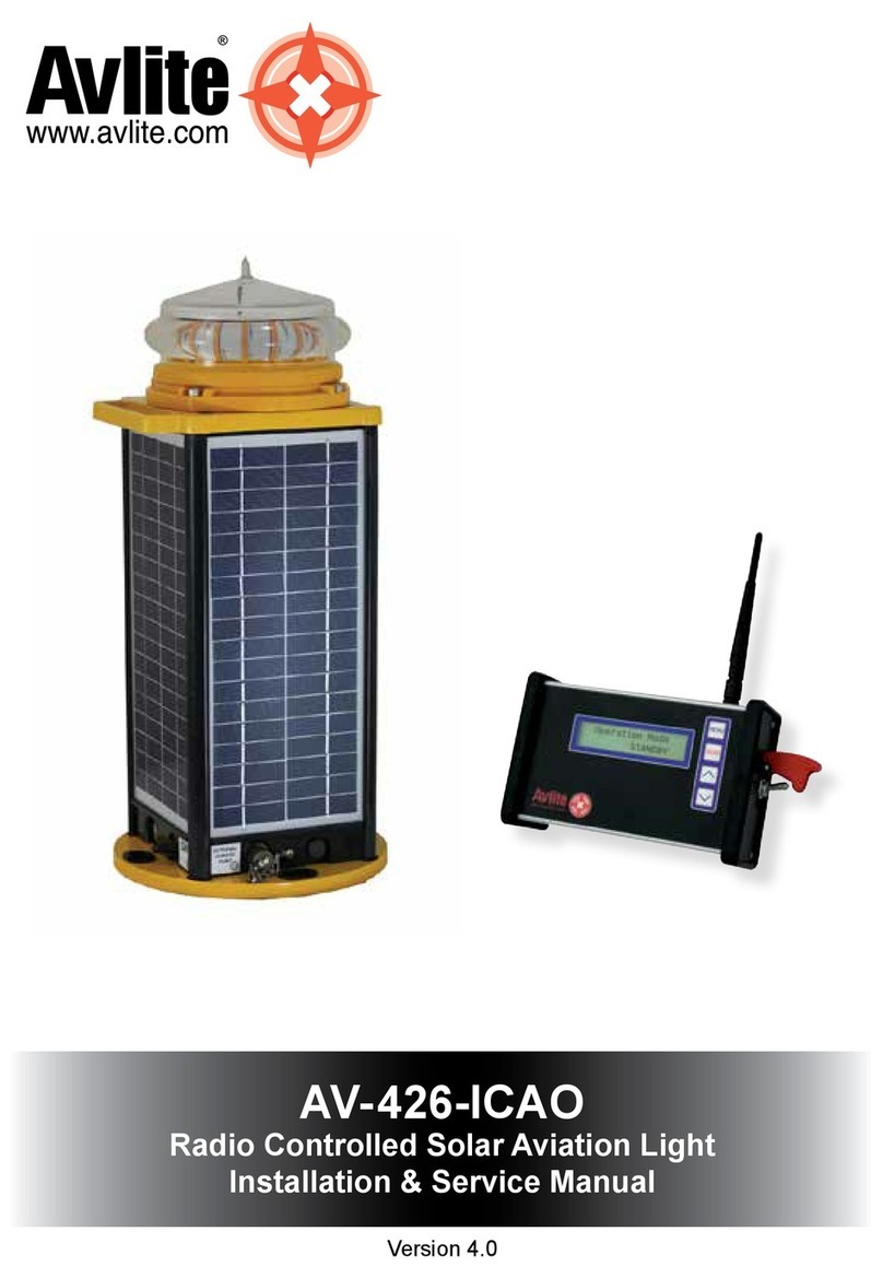
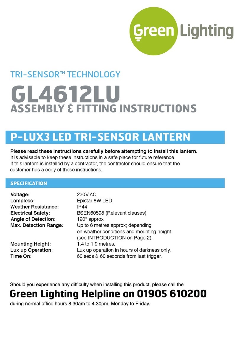
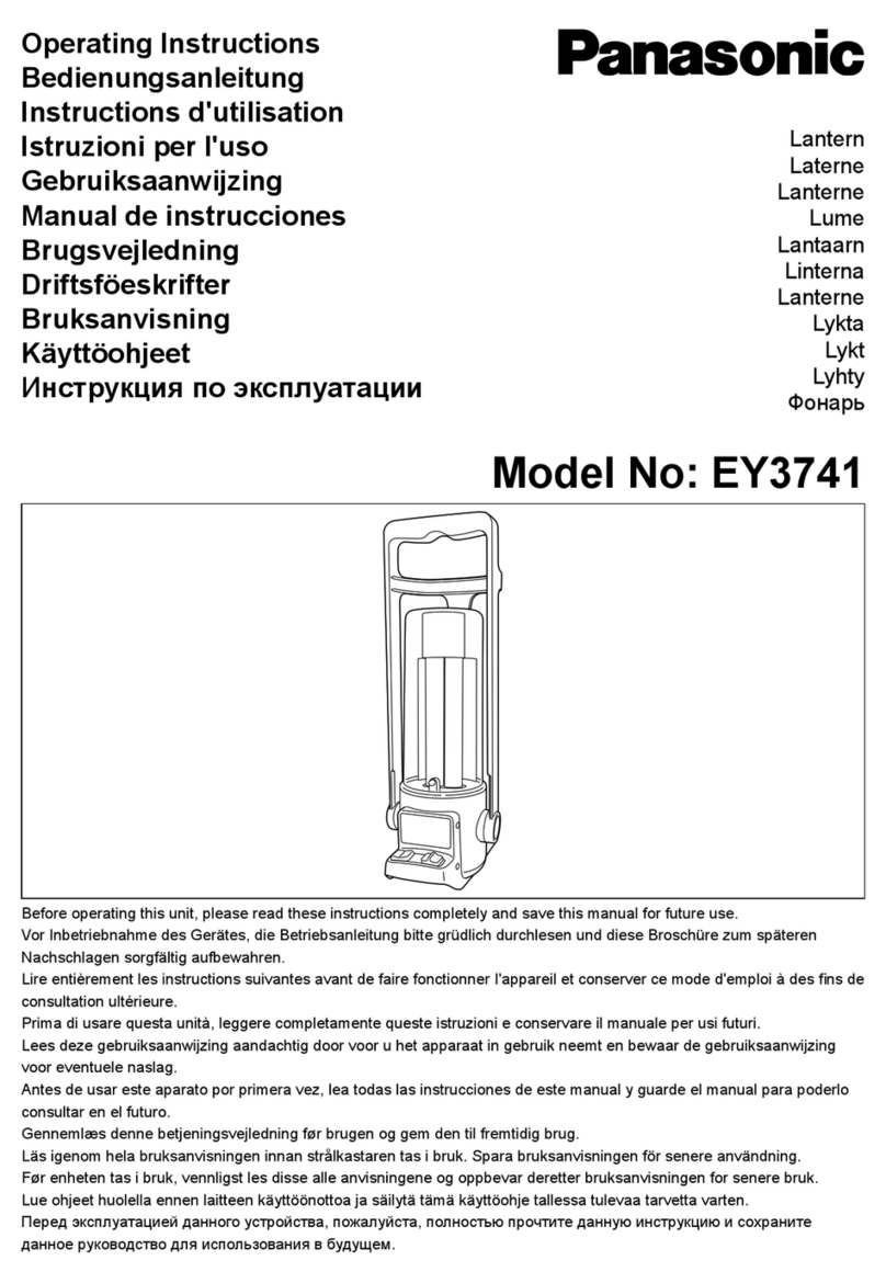
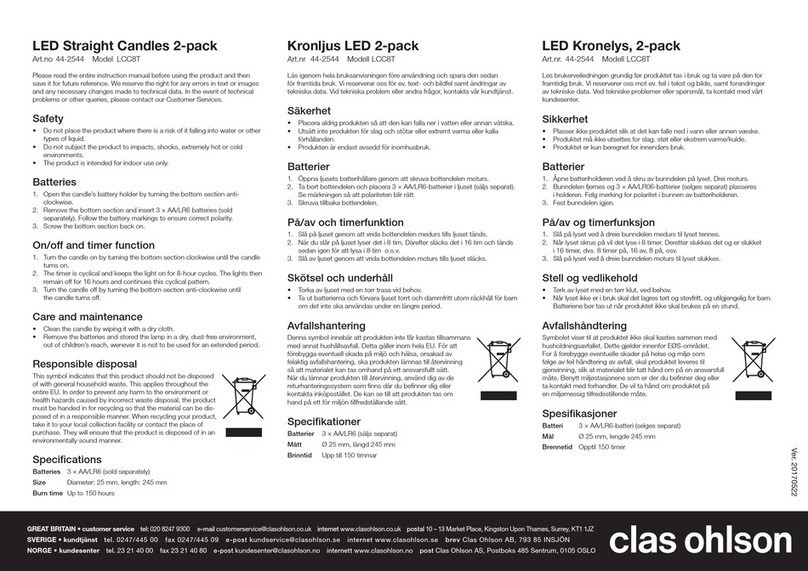
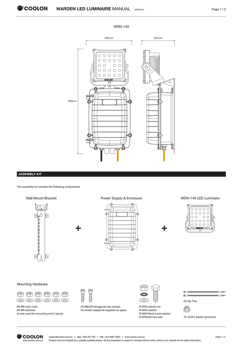
Avlite AV-HLI2 Supplement

V2.0
INSTALLATION & SERVICE MANUAL
AV-HLI2
Inset Heliport Light

2
Version No. Description Date Reviewed Approved Design
1.0 AV-HLI2 Manual Launch Dec 2016 W. Evans
1.1 General Update Feb 2017 W. Evans
1.2 Drawing Update Feb 2017 W. Evans
1.3 General Update Feb 2017 W. Evans
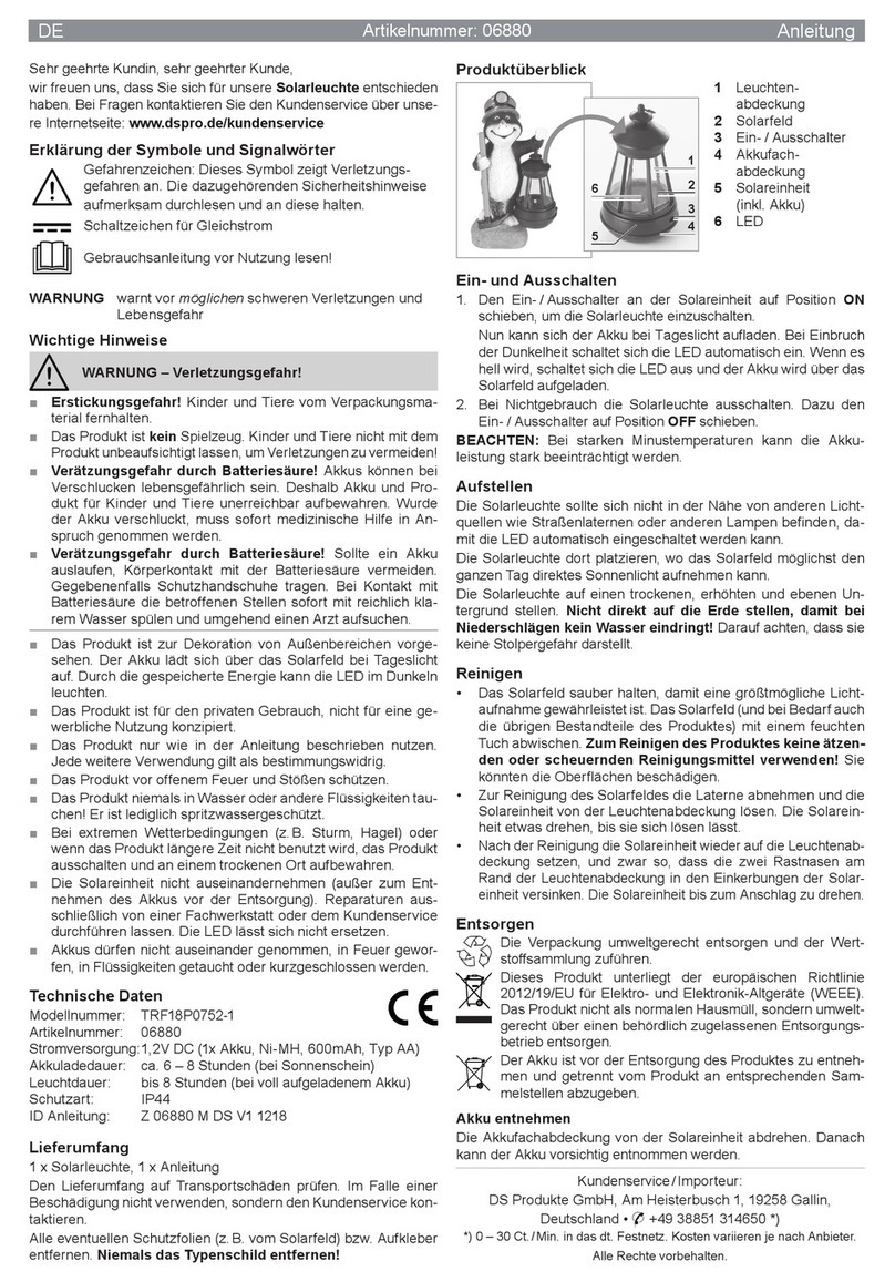
2.0 AV-HLI2 Manual Overhaul July 2020 P. Naidu W. Evans M. Sugars

AV-HLI2 - Inset Heliport Light
Installation & Service Manual
Latest products and information available at www.avlite.com 3
Table of Contents
1.0 Introduction ...............................................................................................................4
2.0 Technology.................................................................................................................5
3.0 AV-HLI2 Models .........................................................................................................6
4.0 AV-HLI2 Data Sheet ..................................................................................................7
5.0 Safety Information....................................................................................................8
6.0 Operation and Setup................................................................................................9
7.0 Unpacking, Installation, Wiring and Setup .........................................................10
7.1 Unpacking ..................................................................................................................................................... 10
7.2 Installation..................................................................................................................................................... 10
8.0 Maintenance and Servicing .................................................................................. 14
9.0 Replacement Parts ................................................................................................. 14
10.0 Troubleshooting....................................................................................................... 15

4
1.0 Introduction
Congratulations! By choosing to purchase an Avlite product, you have become the owner
of one of the most advanced heliport products in the world.
Avlite Systems draws on more than 25 years of experience in the design and manufacture
of navigation aids, and particular care has been taken to ensure your product gives years
of trouble-free service.
As a commitment to producing the highest quality products for our customers, Avlite has
been independently certified as complying with the requirements of ISO 9001:2015 quality
management system.
By taking a few moments to browse through this booklet, you will become familiar with the
versatility of your product, and be able to maximise its operating function.
Please remember to complete the Avlite warranty registration card accompanying your
product.
Acronyms and Abbreviations
The following abbreviations will be used throughout this Installation Manual:
cd candela
ft. foot
in. inch
LED Light Emitting Diode
VAC Volts, Alternating Current
VDC Volts, Direct Current
AWG American Wire Gauge
HLS Heliport Lighting System
TLOF Touch Down and Lift Off
FATO Final Approach and Take Off
API Aim Point Indicator
ADI Aim Direction Indicator

AV-HLI2 - Inset Heliport Light
Installation & Service Manual
Latest products and information available at www.avlite.com 5
2.0 Technology
Avlite Systems is a world-class lighting systems manufacturer with a proven reputation
for rapid, innovative, and agile technology solutions designed specifically for defence,
government, civil and humanitarian aid operations in the most remote, toughest
environments.
Electronics
Avlite employs leading in-house electronic engineers in the design and development of
software and related circuitry. All individual electronic components are sourced directly by
Avlite procurement staff ensuring that only the highest quality components are used in our
products.
LED Technology
All Avlite lights use the latest advancements in LED (Light Emitting Diode) technology as a
light source. The major advantage of LED’s over traditional light sources is well established
in that they typically have an operational life in excess of 100,000 hours, resulting in
substantial savings to maintenance and servicing costs.
Precision Construction
Commitment to investing in the design and construction of injection-moulded parts
including optic lenses, light bases and a range of other components ensures that all Avlite
products are of a consistent and superior quality.
Optical Performance
Avlite manufactures a range of aviation LED lenses moulded from multi-cavity dies. The
company has superior in-house lens manufacturing capabilities to support outstanding
optical performance.
Award-winning, Patented Technology
Several United States and Australian patent registrations are held on Avlite’s range of
innovative designs, with other regional patents pending in Canada, United Kingdom and
Europe.

6
3.0 AV-HLI2
The AV-HLI2 is an inset helipad light designed to comply with ICAO Annex 14, Volume II and
FAA EB67D requirements in a compact and low profile fixture. The fixture is available in
TLOF, FATO, ADI & API configurations to fulfil all surface level and elevated helipad lighting
needs.
As an alternative to elevated lights, Avlite’s inset helipad lights are an excellent choice for
locations where elevated lights are not suitable or are at risk of causing interference to
passing aircraft and maintenance vehicles. The lights can be dimmed from 100%–0 to suit
the application and are available with optional infrared (IR) visibility for pilots using night
vision.
The inset helipad lights are compatible with existing infrastructure and come with a simple
plug and play connection making them simple to install.
Note: This installation and service manual must be used in conjunction with the installation
manuals of the following components (where applicable):
• AV-HL-CTRL-T1
• AV-HL-CTRL-T2
• AV-PALC

AV-HLI2 - Inset Heliport Light
Installation & Service Manual
Latest products and information available at www.avlite.com 7
4.0 AV-HLI2 Data Sheet
AV-HLI2 Inset Light
Light Characteristics
Light Source LED
Available colours Green, White, Yellow, Blue, IR
Peak Intensity - Visible (cd) Complies to: ICAO Annex 14 Vol 2., FAA EB 87, CAP 437
Peak Intensity - IR (mW/str) 240
Intensity/dimming Visible Option: 0 to 100% dimmable
IR Option: IR continuous on, with LCMS and IR switchable
LED Life Expectancy (hours) >100,000
Electrical Characteristics
Operating Voltage (VDC) 18 – 30 V
Power (W)
TLOF/Approach Direction Indicator: max 6.5W
FATO/Aim Point Indicator: max 12.5W
IR model: additional 0.3W
Operating Temperature -40 to 55 °C
Storage Temperature -40 to 85 °C
Physical Characteristics
Dimensions Height
(mm /inches)
Lens
Diameter
(mm/inches)
Diameter
(mm/inches)
Mass (kg/lbs)
AV-HLI2 52.5 / 2 80 / 3⁄ 120 / 4¾ 0.9 / 2
Body Material Corrosion resistant anodised aluminium
Mounting 4 x M5 Screws
Lens Design LED optic
Certifications and Compliance
CE EN61000-6-3:2007, EN61000-6-1:2007
Quality Assurance ISO9001:2015
Protection Rating IP68
Intellectual Property
Trademarks AVLITE®is a registered trademark of Avlite Systems
Warranty+2 year warranty
Options Available • AC/DC converter for AC/DC
• Variety of solar/battery configurations
• Adaptor Plate for mounting in 8” Shallow Bases according to
IEC TS 61827 / FAA AC 5439/150-46D
• 5” or 8” Shallow Base
• LCMS Helipad Control System

8
5.0 Safety Information
Before proceeding with installation or service, make sure the following conditions are met:
• Ensure power lines are not ‘live’ (NO ELECTRICAL HAZARD)
• Avoid touching live circuits!
• Avoid touching any component or any part of the circuitry while the unit is operating.
Do not change components or make adjustments inside the unit with power on.
• Make sure the light fixture mounting is vertically aligned to guarantee the required
beam pattern of the heliport light.
• Make sure any nearby obstacles do not impede the lights’ beam pattern.
• When installing, comply with all local electrical code(s).
• Mains power should always be disconnected when work is being done in close
proximity to electrical fittings, and electrical work should only be done by a licensed
electrician.
• Operate the light only within the indicated electrical ratings and product usage
instructions.
• To ensure that the light and peripheral equipment function safely and correctly, use
cable in compliance with the effective local electrical code.
• Do not stare at the LED or shine the LED into your eyes or those of another person.
• Dispose of the product according to the local laws and regulations for your region, for
example, at a recycling centre that accepts electronic devices.

AV-HLI2 - Inset Heliport Light
Installation & Service Manual
Latest products and information available at www.avlite.com 9
6.0 Operation and Setup
The inset heliport light fixture is available in DC configuration with AC available. The FATO
and TLOF circuits are based on a daisy chained architecture (with or without the aid of
junction boxes). Each light circuit is connected to the Primary Controller individually.
External
6.1 Product Overview
Power
Positive (+24 VDC) Red
Ground BlueBlue
Dimming (0-10 VDC) WhiteWhite
[4.72in]
120mm
[2.06in]
52.5mm
[3.15in]
80mm

10
7.0 Unpacking, Installation, Wiring and
Setup
7.1 Unpacking
Unpack all hardware and inspect for damage. If there is any damage, please contact your
Avlite Office.
Retain original packing material for possible future use in shipping.
7.2 Installation
WARNING:
DO NOT connect directly to the DC output of a generator, or any
other unregulated power source. Connecting to an unregulated
source may result in damage.
WARNING:
Do not stare into light emitting diode (LED) beams.
7.2.1 Tools Required
7.2.2 Location
Refer to your regional specifications for site requirements for heliport lights.
7.2.3 Cabling Requirements
The minimum cable requirements are set out in the relevant AV-HL-CTRL Installation and
Service Manual.
Tools Needed (not supplied)
5mm Allen Key

AV-HLI2 - Inset Heliport Light
Installation & Service Manual
Latest products and information available at www.avlite.com 11
7.2.4 Installation Recommendation
Electrical inspection and test
The inset light is manufactured with a 3 core input fly lead, of default length. One end of
the input cable is molded into the light fixture and the other end is terminated with colour
coded ferrules. Refer to 6.1 Product Overview for details on each conductor and their
function.
To test the light fixture, connect a 24VDC source to the two input power wires in
accordance with the table in section 6.1 Product Overview and apply power, this should
result in the light turning on at full (100%) intensity. If dimming is required, connect a
variable 0-10VDC source to the remaining conductor. Dimming occurs in accordance with
the following table:
Preparation of installation location
The AV-HLI2 can be installed in either a 5” (inch), 8” (inch) or direct mounting configuration.
5” Configuration:
For installation in tarmac or concrete helipads it is recommended to use the Avlite 5” (inch)
inset shallow base taking into consideration site specific bearing load, leveling and thermal
bonding.
For installations using the 5” inset base configuration, please see mechanical specifications:
8” Configuration:
For installations where there are pre-existing 8” mounting locations or 8” mounting is
desired then the Avlite 5” to 8”, adaptor ring and AV-MC-54, 8” inset shallow base is
required.
Note: Reuse of the M10x15 screws is not recommended
For installations using the 8” inset base configuration, the installation location of each light
needs to prepared in accordance with the below mechanical specifications:
Direct Mounting:
For installations where direct mounting of the light fixture to a metal helipad surface is
desired, the mounting surface of each light must be prepared in accordance with the
following mechanical specification ensuring the mounting surface is level and has adequate
heat dissipation characteristics.
Intensity Voltage
100% <0.5V
30% 3.5V
10% 8.5V
0% (Off) >9.5V

12
Electrical Installation
The procedure for connecting the inset light fixture to the corresponding electrical
connections is as follows:
• Feed input and output cables through corresponding side mounted gland on inset
base
• Connect each conductor of input cable to separate joint connector (not supplied). One
for +24VDC, one for GND (0VDC) and one for Dim (0-10V) control line.
• Connect each conductor of output cable to corresponding joint connector
• Connect each conductor of light fly lead to corresponding joint connector as per table
• Tighten each cable gland to ensure sealing
Note: Do not cut or modify the fly lead attached to the AV-HLI2 light fixture
Mechanical Installation
5” Configuration:
The procedure for installing an inset light fixture to a 5” base is as follows:
• Ensure the M5 screw holes and flange area on the 5” inset base are clean
• Lower the light fixture onto the inset base, ensuring all electrical connections are
properly terminated and fly lead is free and clear of the mounting surface
• Align the screw holes of the inset light fixture with those of the inset base and fasten
using silicone greased M10x15 counter sunk screws
• Tighten screws to 4.9 Nm
8” Configuration:
The procedure for installing the adaptor ring onto the inset light fixture and fitting to a 8”
base is as follows:
• Ensure the M10 screw holes and flange area on the 8” inset base are clean Insert the
provided O-ring into the O-ring groove of the adaptor ring
• Lower the light fixture onto the inset base, ensuring all electrical connections are
properly terminated and fly lead is free and clear of the mounting surface
• Align the screw holes of the inset light fixture with those of the inset base and fasten
using silicone greased M5x12 counter sunk screws
• Tighten screws to 4.9 Nm

AV-HLI2 - Inset Heliport Light
Installation & Service Manual
Latest products and information available at www.avlite.com 13
Direct Mounting:
The procedure for installing an inset light fixture to a pre-prepared mounting surface is as
follows:
• Ensure the M5 screw holes and flange area are clean
• Lower the light fixture onto the mounting surface, ensuring all electrical connections
are properly terminated and fly lead is free and clear of the mounting surface
• Align the screw holes of the inset light fixture with those of the mounting surface and
fasten using silicone greased M10x15 counter sunk screws
• Tighten screws to 3.5 Nm
Note: Continuous Immersion of the light (body) into water/fluids:
It is required to install the light in such way that no frequent or continuous immersion of
the light or parts in water or other fluids take place. Therefore it is recommended to use
the shallow base, either connected to a drained duct system or by inserting the cables
(sheated cable OD 7-13mm) through the cable glands and tightening them with 12 Nm
torque. When inserting the lights in the shallow base, ensure the provided sealing “O-ring”
is in the correct position below the flange of the light and in the chamfer of the shallow
base. Apply anti-seizing to the 4 screws and tighten the screws with 4.9 Nm crosswise.
Note: Intrusion of water through the supply cable:
The open ends of the power supply cables of the light and on the construction side shall
not be immersed into water at any time of the installation. If this accidentally happens, the
lines need to be dried by unstripping the cable ends and storing them in a drying agent (eg.
a bag with silica gel and tyrap) for a minimum of 5 days. For connection, we recommend
the usage of gel filled joints suiting 0.75mm² up to 4mm² wiring. If an intrusion of water
in the bases or pits cannot be avoided, the joints should be placed in such way that no
immersion in water or other fluids can take place.

14
8.0 Maintenance and Servicing
Designed to be almost maintenance free the inset helipad light requires minimal attention,
though the following maintenance and servicing information is provided to help ensure the
life of your Avlite product.
• Occasional cleaning of the lens may be required using a cloth and warm soapy water.
• Monthly check of the torque of the light head to its mounting.
9.0 Replacement Parts
If replacement parts are required, please call a local Avlite distributor and reference the
Product or Configuration Code called out in the “Product Configuration and Options” section
of the corresponding product data sheet.

AV-HLI2 - Inset Heliport Light
Installation & Service Manual
Latest products and information available at www.avlite.com 15
10.0 Troubleshooting
Problem Possible Cause Solution
Light will not
activate
• No power at unit
• Unit is damaged
• Remove light from mount
• Ensure 24VDC supply source is active
• Check that 24VDC is present at joint
connector feed the light fixture
• Check polarity of supply line wires is
correct
• Measure voltage of Dim line and check
against the table dimming table
• If measured voltage on Dim line is less
than 0.5V, remove dim line connection
and check light functionality
• Otherwise replace the light fixture
Intensity does
not match
• No Analog Input
connection
• Incorrect Analog
input voltage
• Remove light from mount
• Measure voltage of Dim line and check
againstthe table dimming table
• If measured voltage does not match
the expected value disconnect the
light from the Dim line and re-measure
• If measured voltage on the Dim line
still does not match expected value,
inspect the dim line wiring
• Otherwise replace the light fixture
Notes

Avlite Solution Verticals available
Avlite Systems
Australia
+61 (0)3 5977 6128
Avlite Asia Pte Ltd
Singapore
+65 6908 2917
Avlite USA LLC
USA
+1 (603) 737 1311
We believe technology improves navigationTM
avlite.com info@avlite.com
Airfield
Heliport
Obstruction
Other manuals for AV-HLI2
1
Table of contents
Other Avlite Lantern manuals
Popular Lantern manuals by other brands

olympia electronics
olympia electronics Double Easy Light GR-391/L quick start guide

Glamox
Glamox C20-S3/P3 Service manual

Winsome house
Winsome house WHSL472 instruction manual

Fumagalli
Fumagalli SILOE quick guide

KingShield
KingShield ELTSLED65NM Installation & operating instructions

Heitronic
Heitronic 35470 Installation and operating instructions

Sealite
Sealite Apollo-155 Installation and programming manual

Seto
Seto ALDEBARAN 5000 Instructions for use

Cosi
Cosi Cosiscoop Bamboo User instructions

Clevertronics
Clevertronics L10 LWFLED Installation & maintenance

Hess
Hess BURGOS Installation and operating instructions

BEGA
BEGA 24 816 Instructions for use