Deluce Lighting LED RGB IP65 Strip Kit User manual

These instructions are for the Déluce Lighting LED RGB IP65 Strip Kit :
LEDSTRIPKIT/RGB
LED STRIP KIT
FITTING INSTRUCTIONS
(RGB COLOUR - IP65)
DEL0670h/Feb_2017/issue_1 page 1 of 3
www.delucelighting.com
IMPORTANT INSTALLATION INFORMATION
• Installation should be carried out in accordance with the latest edition of
the IEE Wiring Regulations (BS7671) and taking into consideration the latest
Building Regulations. If in doubt, consult a qualified electrician.
• Before commencing any installation or maintenance work, ensure
electricity is switched off at the mains.
• Please take note of the maximum rated voltage for your LED Strip Light.
• Please take note of the IP (Ingress Protection) rating of LED RGB Strip Light
when deciding location.
GENERAL INSTALLATION - SAFETY
• Please make sure you are safe when working at height.
• Employ the latest safety regulations and procedures to ensure the safe
installation of the LED RGB Strip Light.
INSTALLATION INSTRUCTIONS
• To achieve the best results from your LED RGB Strip Light we suggest you
take into account the following points before you fit the unit.
1. Ensure the mounting surface is clean and free of dust, grease or flaking
material
2. Peel back the protective film away from the strip exposing the glue and
apply to the mounting surface in the required location.
3. When the desired length as been mounted, cut the length
at the designated cutting line; marked with a ✂
4. Connect the LED Strip cable to the Controller as follows:
WHITE (Positive +) to +
GREEN to G
RED to R
BLUE to B
Then connect the Controller to the Driver as follows:
RED / BROWN (Positive +) + to +
BLACK / BLUE (Negative –) – to –
5. Connect the supply cable to the Driver via a suitable terminal block and
make the electrical connections as follows:
LIVE - (Red or Brown)
NEUTRAL - (Black or Blue)
EARTH - (Green/Yellow) marked E
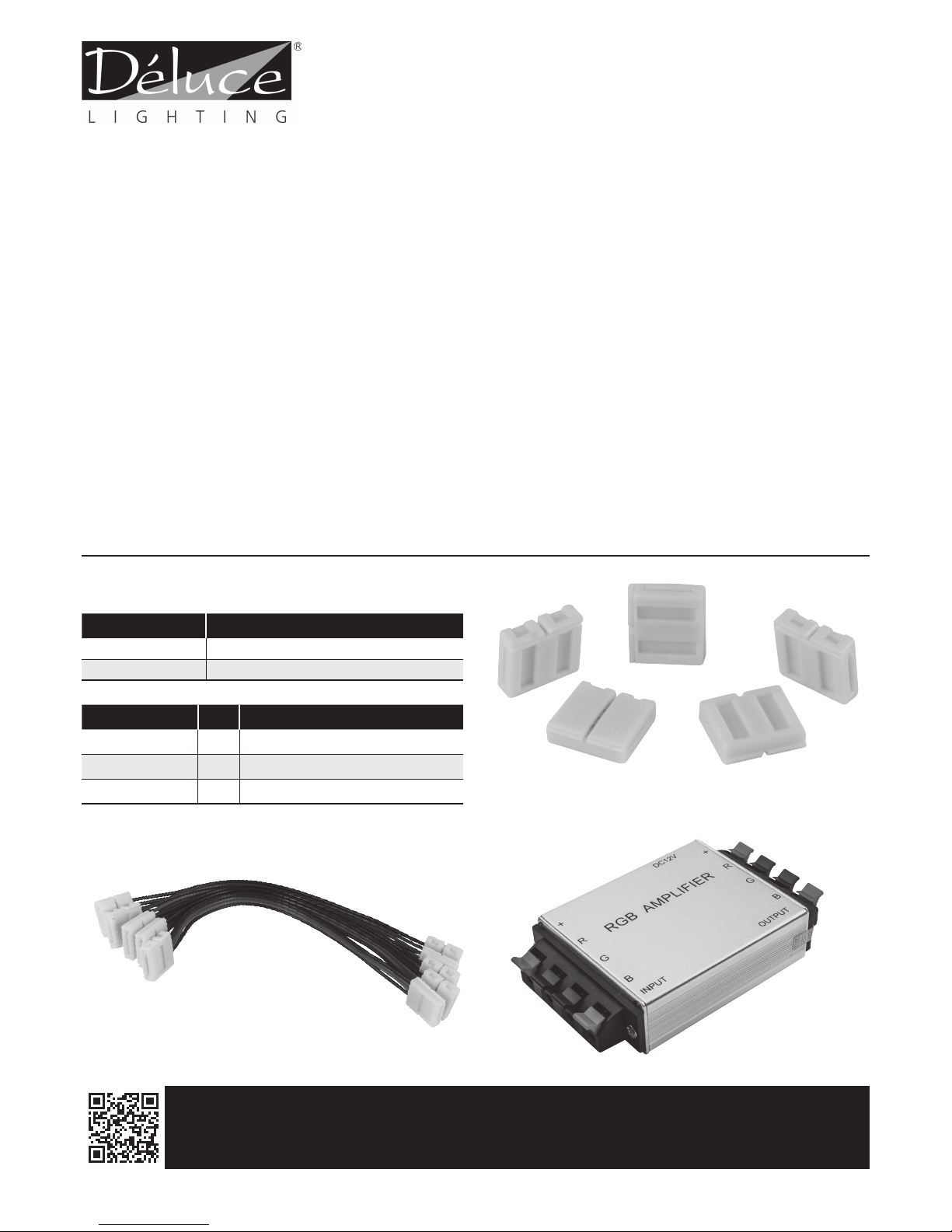
Ref no. Watts Description Length No. of
LED’s
LEDSTRIPKIT/RGB 36W RGB colour changing stand alone LED
strip light c/w remote control & receiver 5m 150
150
G
R
B
16.6
100
5 metres
32.2 32.2 32.2
12
3.4
All dimensions in millimetres unless stated
100
Dimensions and Schematic Diagram
6. Ensure that the LED RGB strip load does not exceed that
of the driver, the driver supplied can power a maximum
continuous run of LED RGB strip lights of 5 Metres.
7. Switch on the power supply for testing and adjustment.
8. Over the tailing end of the LED strip light fit an End Cap
(apply a small amount of glue to the inside of the end
cap and then slide over the tailing end area).
PLEASE READ THESE INSTRUCTIONS CAREFULLY BEFORE INSTALLATION
LEAVE A COPY FOR THE USER/MAINTENANCE ENGINEER FOR FUTURE REFERENCE
We recommend this fitting is installed by a qualified Electrician.
GUARANTEE
This product is guaranteed in the EU for a period of 1 year from the date of purchase. The guarantee is invalid in the case of improper use, installation, tampering, removal of the
QC date label, installation in an improper working environment or installation not according to the current edition of the IEE Wiring Regulations (BS 7671). Should this product
fail during the guarantee period it will be replaced free of charge, subject to correct installation and return of the faulty unit. Déluce Lighting does not accept responsibility for any
installation costs associated with the replacement of this product. Your statutory rights are not affected. Déluce Lighting reserves the right to alter specifications without prior notice.
IP65
220-240V
LED

LED STRIP KIT
FITTING INSTRUCTIONS
(RGB COLOUR - IP65)
DEL0670h/Feb_2017/issue_1 page 2 of 3
www.delucelighting.com
Installation instructions for MULTIPLE kits
Then follow the steps 1 - 7 for connection.
To install multiple units requires an RGB signal amplifier, part code: LEDSTRIPRGBAMP, for each RGB LED strip kit installed.
Each Driver needs it’s own mains supply also - see diagram belown. A maximum of up to 20 RGB kits can be used in one installation.
Note: A maximum of up to 20 RGB kits can be used in one installation.
MAINS POWER
SUPPLY 240V
DRIVER DRIVER
WIRELESS
RECEIVER AMPLIFIER
RGB LED
STRIP LIGHT
RGB LED
STRIP LIGHT
RGB LED
STRIP LIGHT
REMOTE CONTROL
RGB LED Strip wiring diagram
N
L
AMPLIFIER
MAINS POWER
SUPPLY 240V
KEY
Single Colour LED Strip wiring diagram
4 core cable (RGB +)
Live mains 240V
Neutral mains 240V
N
L
Maximum of 8 METRES
DRIVER ONE Colour
LED STRIP LIGHT
DRIVER
G
R
B
G
R
B
DC12 CONTROLLER
CONTROLLER
DRIVER WHITE
GREEN
RED
BLUE
BROWN/
RED
BLUE/
BLACK
230V AC
G
G
R
B
R B
G
R
B
G
R
B
DC12
CONTROLLER
CONTROLLER
DRIVER WHITE
GREEN
RED
BLUE
BROWN/
RED
BLUE/
BLACK
230V AC
G
G
R
B
R B
Brightness Up + Brightness Down - OFF ON
Static Red Static Green Static Blue Static White
Static Orange Static Light Green Static Dark Blue Static Milk White
Static Dark Yellow Static Cyan Static Lyons Blue Static White Pink
Static Yellow Static Light Blue Static Purple Static Green White
Static Light Yellow Static Sky Blue Static Brown Static Blue White
W Brightness Up + W Brightness Down - White Light OFF White Light ON
25% W brightness 50% W brightness 75% W brightness 100% W brightness
Jump 3 Fade 3 Jump 7 Quick
Fade 7 Flash Auto Slow
Remote control functions ( each buttons function )
PLEASE READ THESE INSTRUCTIONS CAREFULLY BEFORE INSTALLATION
LEAVE A COPY FOR THE USER/MAINTENANCE ENGINEER FOR FUTURE REFERENCE
We recommend this fitting is installed by a qualified Electrician.
OFF
R G
ON
OFF
JUMP 3
25% 50% 75% 100%
FADE 7 FLASH AUTO SLOW
FADE 3 JUMP 7 QUICK
ON
B W
Brightness
+
Brightness
-
OFF
Static
Colour
Hot
Keys
W Brightness + / -
3 Colour Jump Speed +
White Light
On / Off
Speed -
7 Colour Jump
Automatic Cycle
7 Colour Fade
3 Colour Fade
White Brightness
Hot Keys
7 Colour
& White Strobe
ON
The controller is divided into two areas ( RGB and W[ white ] mode ), which can be turned on
and off independently, and can control the brightness and the colour independently.
When the RGB mode is turned on, it can change the RGB colour and brightness, the White mode
can be turned on and off at the same time, the white mode can be partly turned on or off and the
brightness of the white mode and be adjusted. The 3 or 7 Fade function button adjusts the speed
of the colour fading. The 3 or 7 Jump function button adjusts the speed of the brightness change.
The speed of the function buttons can be adjusted via the Quick or Slow buttons.
All images and drawings are for illustration purposes only !

LED STRIP KIT
FITTING INSTRUCTIONS
(RGB COLOUR - IP65)
DEL0670h/Feb_2017/issue_1 page 3 of 3
www.delucelighting.com
Cutting the LED Strip Light
The LED RGB Strip can be cut at 100mm intervals and can be relinked using either a connect clip, a double ended connector cable
c/w 150mm of cable, single ended connector clip c/w 150mm of cable or by soldering a cable between the LED Strip Light's copper
connectors (all connectors supplied with kit).
Cut the LED strip at the designated cutting line, marked with a ✂ its is recommended that a suitable craft knife is used to cut the
LED Strip Light.
Once cut; use the craft knife to remove the outer plastic sleeve, as close to the nearest LED light, near the cut as possible to expose
the copper connectors ( marked + & – ).
Slide a piece of heat shrink over the end of the LED strip - open a flap on a connector clip / connector cable - slide the now cleaned
end piece into one side of a connector clip / connector cable and then using a soldering iron, YOU MUST solder the connector
clip's terminals to the LED strips copper connectors in turn.
Or solder a piece of cable between the LED Strip Light's copper connectors as follows :
WHITE to WHITE GREEN to GREEN
RED to RED BLUE to BLUE
Using the supplied glue, glue down the flap(s) of the connector clip; then slide the heat shrink sleeve over the now finished connection
(using a Hair Dryer) heat the heat shrink until it contracts sufficiently.
Over the tailing end of the LED strip light fit an End Cap ( apply a small amount of glue to the inside of the end cap and then slide
over the tailing end area ).
Then follow the steps 1 - 7 for installation.
LED Strip Accessories
Ref no. Qty Description
LEDSTRIPACC004 510mm RGB colour strip connector c/w 150mm
of wire
LEDSTRIPACC005 510mm RGB colour strip connector
LEDSTRIPACC006 510mm RGB colour strip link c/w 150mm of wire -
connector at each end
LEDSTRIPACC006
LEDSTRIPRGBAMP
LEDSTRIPACC005
POLARITIES MUST BE MAINTAINED
PLEASE READ THESE INSTRUCTIONS CAREFULLY BEFORE INSTALLATION
LEAVE A COPY FOR THE USER/MAINTENANCE ENGINEER FOR FUTURE REFERENCE
We recommend this fitting is installed by a qualified Electrician.
Product Code Description
LEDSTRIPDRI40* LED driver - Output 40W
LEDSTRIPRGBAMP Signal amplifier - Max load - additional 5m RGB
This manual suits for next models
1
Popular Lantern manuals by other brands

WE-EF
WE-EF ETC330-FS Installation and maintenance instructions

Sylvania
Sylvania UltraLED Series installation guide

Cosi
Cosi Cosiscoop Urban User instructions

Appleton
Appleton FDBAES Series manual

Cooper Crouse-Hinds
Cooper Crouse-Hinds ILLUMINATOR EVFT Series Installation & maintenance information

WE-EF
WE-EF PFL240 LED Installation and maintenance instructions

LUG
LUG CALIBRO LED 020261.5L03.02 Installation instruction

NORLYS
NORLYS SANDE Assembly / Parts

MEDC
MEDC FL11 Technical manual

Makita
Makita ML102 instruction manual

Visual Comfort & Co.
Visual Comfort & Co. Lafayette NW 2707 Assembly instructions

Visual Comfort & Co.
Visual Comfort & Co. CHO2153 Assembly instructions