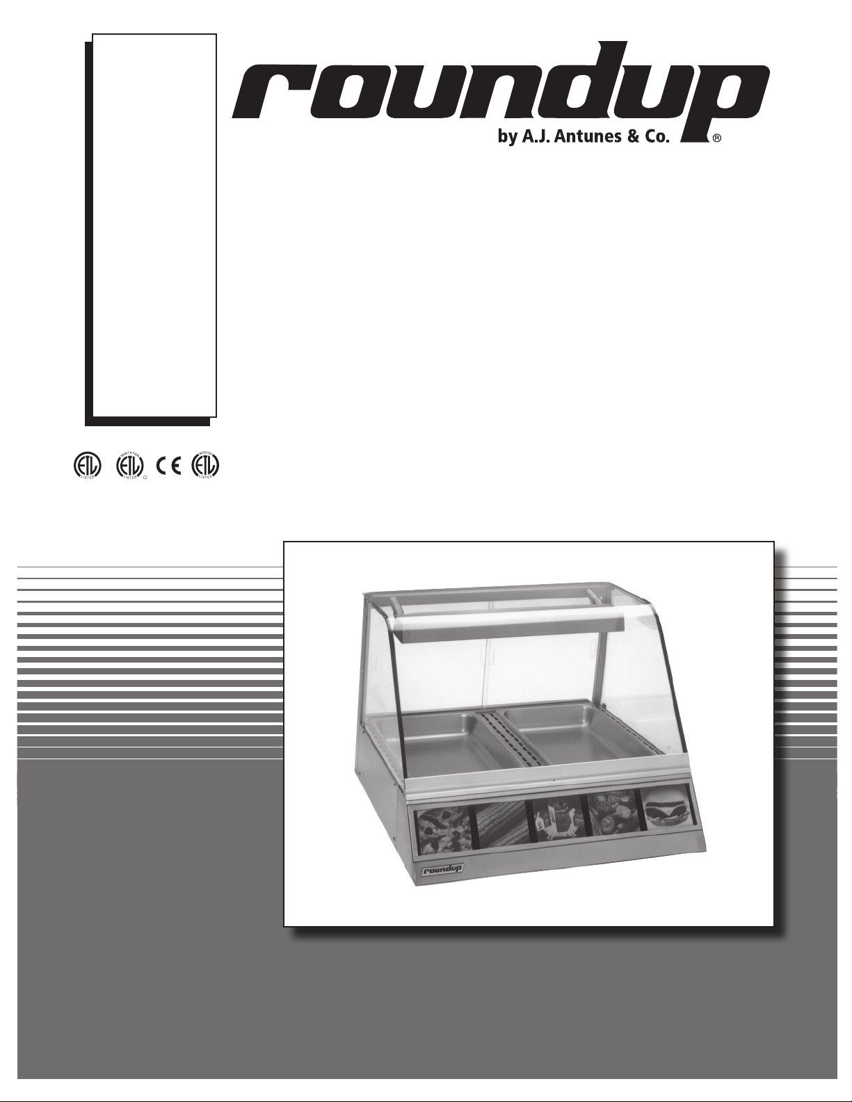
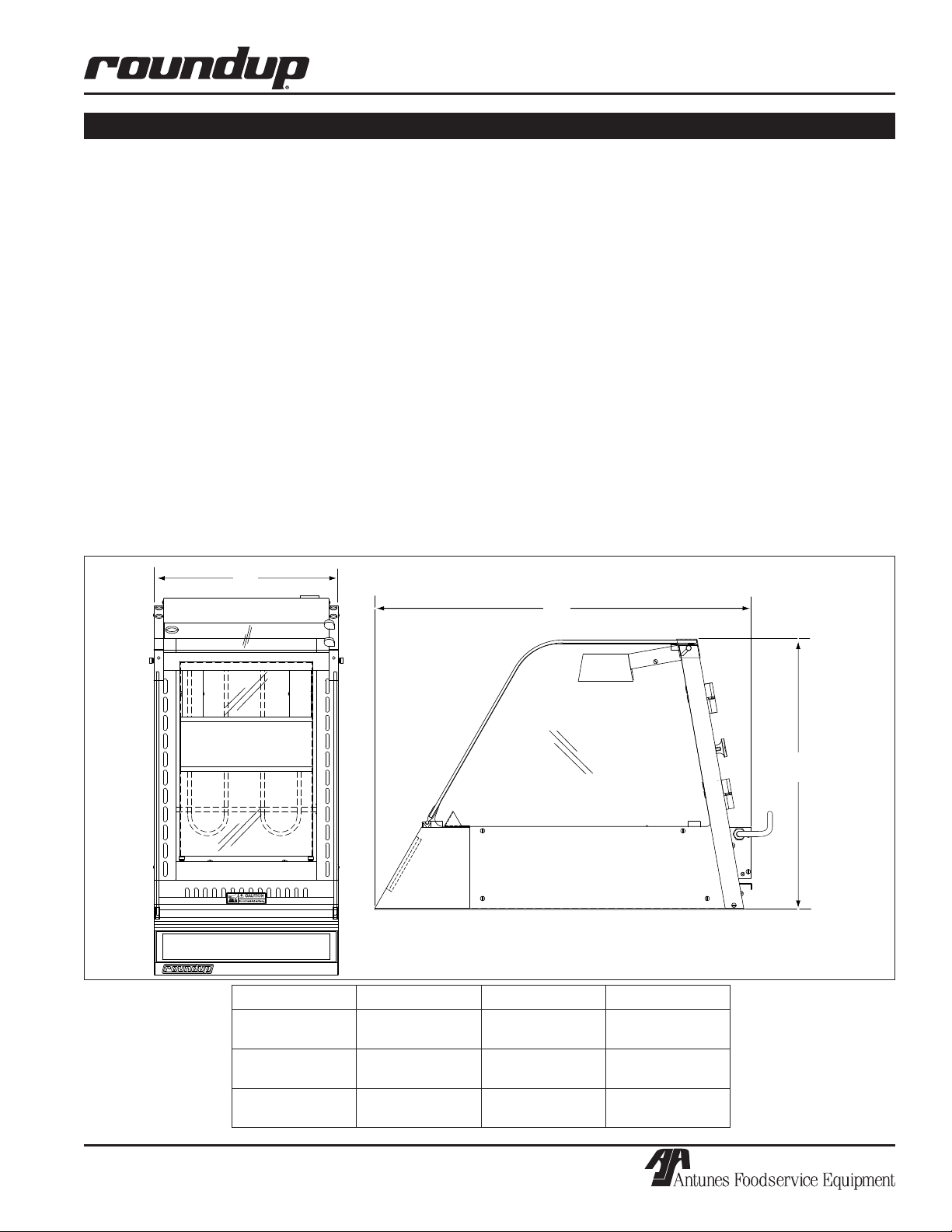
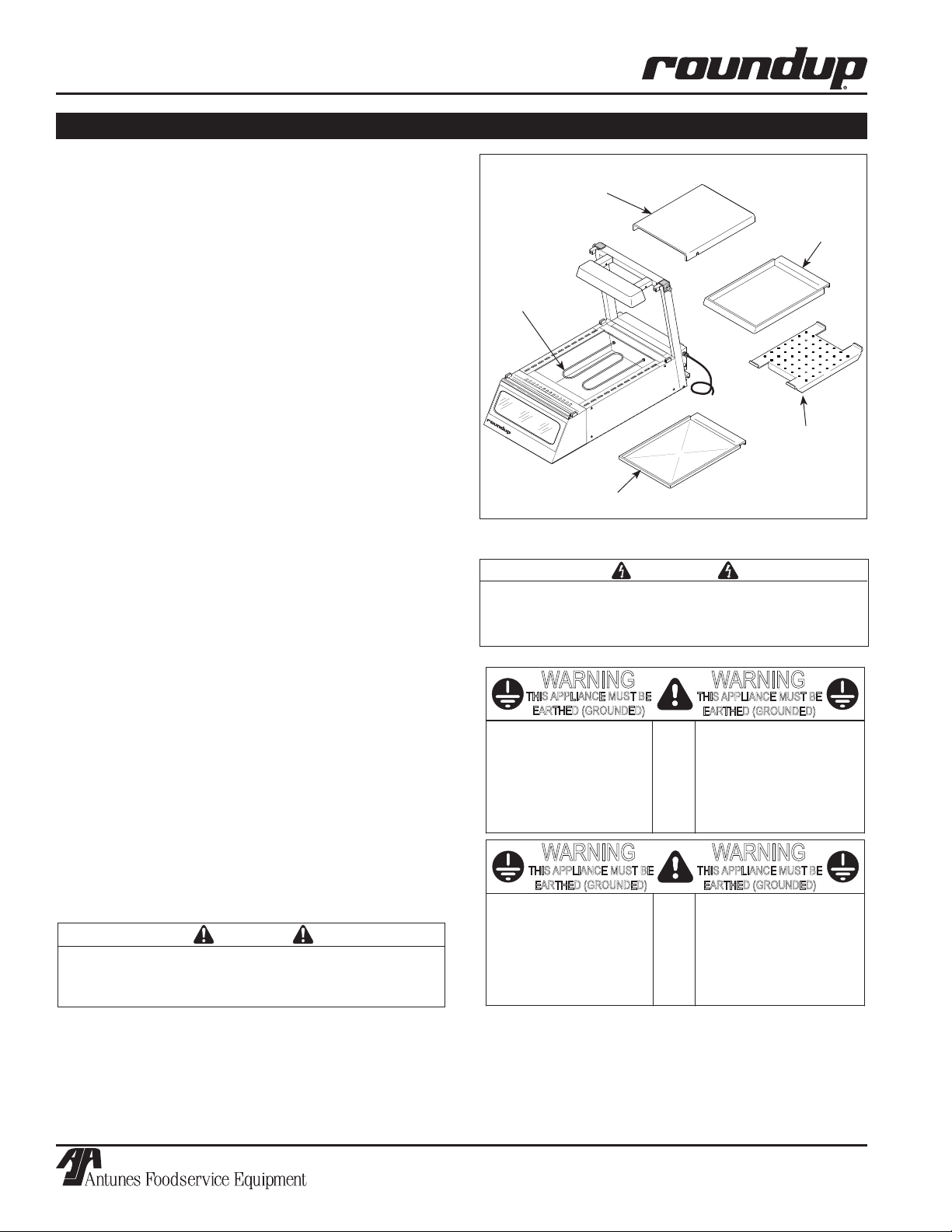
DISPLAY CABINET HEATED
4P/N 1010772 Rev. D 12/13
In addition to the warnings and cautions in this manual,
use the following guidelines for safe operation of the
unit:
• Read all instructions before using equipment.
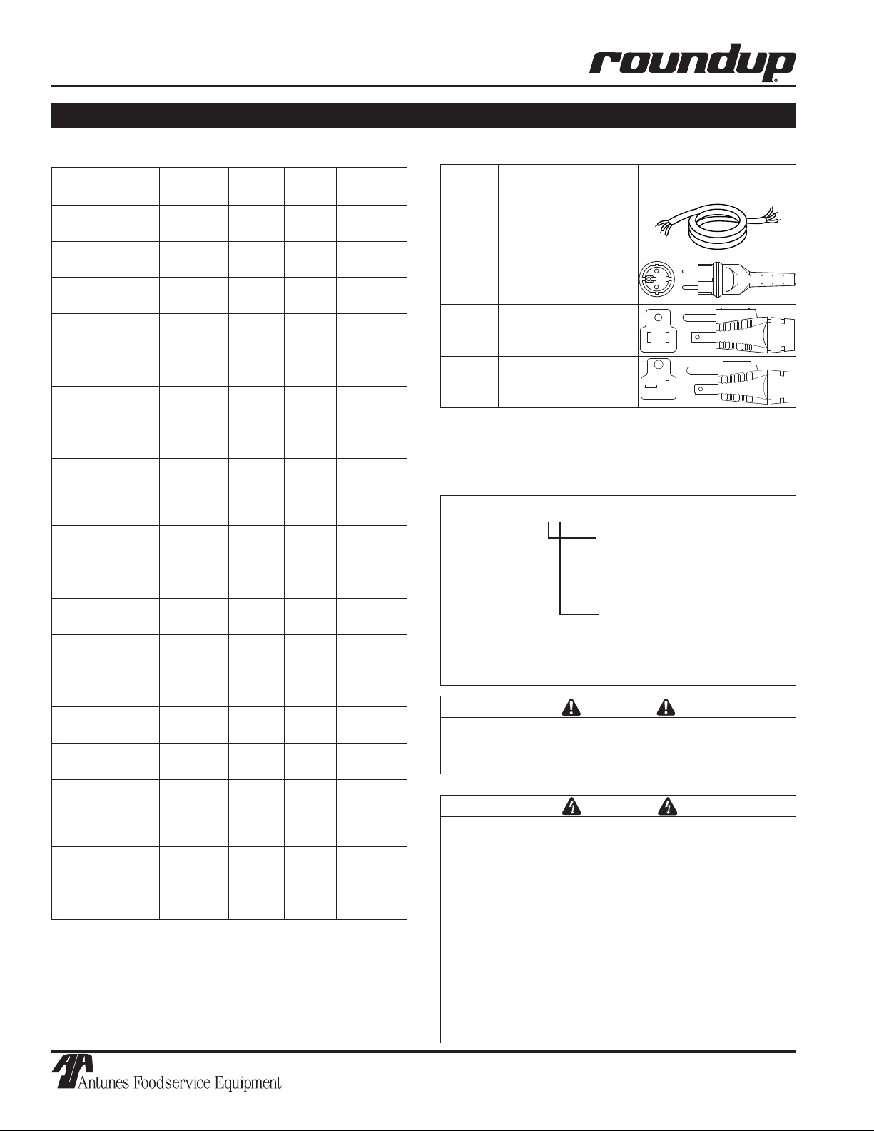
• For your safety, the equipment is furnished with
a properly grounded cord connector. Do not
attempt to defeat the grounded connector.
• Install or locate the equipment only for its intend-
ed use as described in this manual.
• Do not operate this equipment if it has a dam-
aged cord or plug, if it is not working properly, or
if it has been damaged or dropped.
• This equipment should be serviced by qualified
personnel only. Contact the nearest Roundup
authorized service facility for adjustment or repair.
• Do not block or cover any openings on the unit.
• Keep cord away from heated surfaces and do not
allow cord to hang over edge of table or counter.
The following warnings and cautions appear
throughout this manual and should be carefully
observed:
• WARNING ELECTRICAL SHOCK HAZARD.
FAILURE TO FOLLOW THESE INSTRUCTIONS
COULD RESULT IN SERIOUS INJURY OR
DEATH.
• Turn the unit off, disconnect the power
source, and allow unit to cool down before
performing any service or maintenance on the
unit.
• The procedures in this chapter may include
the use of chemical products. These chemi-
cal products will be highlighted with bold
face letters followed by the abbreviated HCS
(Hazard Communication Standard). See
Hazard Communication Standard manual for
the appropriated Material Safety Data Sheets
(MSDS).
• The unit should be grounded according to
local electrical codes to prevent the possibil-
ity of electrical shock. It requires a grounded
receptacle with separate electrical lines, pro-
tected by fuses, or a circuit breaker of the
proper rating:
- Electrical ground is required on this appli-
ance.
- Do not modify the power supply cord plug.
If it does not fit the outlet, have a proper
outlet installed by a qualified electrician.
- Do not use an extension cord with this
appliance.
- Check with a qualified electrician if you
are in doubt as to whether the appliance is
properly grounded.
• All electrical connections must be in accor-
dance with local electrical codes and any
other applicable codes.
• This equipment is to be installed to com-
ply with the basic plumbing code of the
Building Officials and Code Administration,
Inc. (BOCA) and the Food Service Sanitation
Manual of the Food and Drug Administration
(FDA).
• Do not immerse cord or plug in water.
• Do not clean this appliance with a water jet.
• Do not use a sanitizing solution or abrasive
materials. The use of these may cause dam-
age to the stainless steel finish.
• Do not use corrosive chemicals in this equip-
ment.
• Chlorides or phosphates in cleansing agents
(e.g. bleach, sanitizers, degreasers, or deter-
gents) could cause permanent damage to
stainless steel equipment. The damage is
usually in the form of discoloration, dulling
of metal surface finish, pits, voids, holes, or
cracks. This damage is permanent and not
covered by warranty.
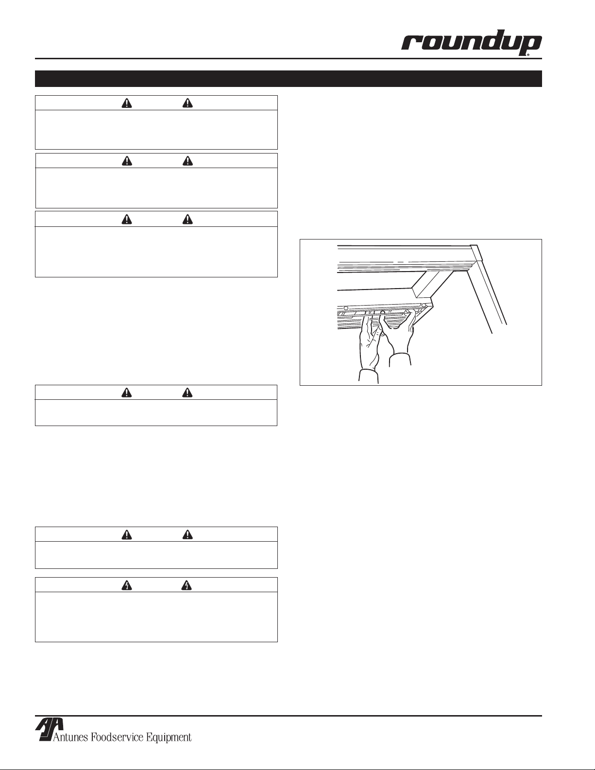
• The following tips are recommended for main-
tenance of your stainless steel equipment:
- Always use soft, damp cloth for cleaning,
rinse with clear water and wipe dry. When
required, always rub in direction of metal
polish lines.
- Routine cleaning should be done daily
using soap, ammonia detergent, and
water.
- Stains and spots should be sponged
using a vinegar solution as required.
- Finger marks and smears should be
rubbed off using soap and water.
- Hard water spots should be sponged
using a vinegar solution.
IMPORTANT SAFETY INFORMATION (continued)