manuals.online logo
Brands
  1. Home
  2. •
  3. Brands
  4. •
  5. A.O. Smith
  6. •
  7. Water Heater
  8. •
  9. A.O. Smith Dura-Power DRE - 120 User manual

A.O. Smith Dura-Power DRE - 120 User manual

This manual suits for next models

1

Other A.O. Smith Water Heater manuals

A.O. Smith ST-400 Troubleshooting guide

A.O. Smith

A.O. Smith ST-400 Troubleshooting guide

A.O. Smith ATX-199 User manual

A.O. Smith

A.O. Smith ATX-199 User manual

A.O. Smith HSE-HAS User manual

A.O. Smith

A.O. Smith HSE-HAS User manual

A.O. Smith 201 Series User manual

A.O. Smith

A.O. Smith 201 Series User manual

A.O. Smith 160M User manual

A.O. Smith

A.O. Smith 160M User manual

A.O. Smith DVE-10.000 User manual

A.O. Smith

A.O. Smith DVE-10.000 User manual

A.O. Smith ST Series Troubleshooting guide

A.O. Smith

A.O. Smith ST Series Troubleshooting guide

A.O. Smith ATMOSPHERIC VENTED WATER HEATER User manual

A.O. Smith

A.O. Smith ATMOSPHERIC VENTED WATER HEATER User manual

A.O. Smith GPDH User manual

A.O. Smith

A.O. Smith GPDH User manual

A.O. Smith BTX-80 User manual

A.O. Smith

A.O. Smith BTX-80 User manual

A.O. Smith BTH-120 through BTH-500 User manual

A.O. Smith

A.O. Smith BTH-120 through BTH-500 User manual

A.O. Smith Gen 8 Digital User manual

A.O. Smith

A.O. Smith Gen 8 Digital User manual

A.O. Smith AOSRG45300 User manual

A.O. Smith

A.O. Smith AOSRG45300 User manual

A.O. Smith BTH 120 How to use

A.O. Smith

A.O. Smith BTH 120 How to use

A.O. Smith FVIR Product information sheet

A.O. Smith

A.O. Smith FVIR Product information sheet

A.O. Smith ITS - 300 User manual

A.O. Smith

A.O. Smith ITS - 300 User manual

A.O. Smith ITE 400 User manual

A.O. Smith

A.O. Smith ITE 400 User manual

A.O. Smith CYCLONE Xi BTH 400A Manual

A.O. Smith

A.O. Smith CYCLONE Xi BTH 400A Manual

A.O. Smith GDV User manual

A.O. Smith

A.O. Smith GDV User manual

A.O. Smith MEV 50 EC User manual

A.O. Smith

A.O. Smith MEV 50 EC User manual

A.O. Smith 500 Guide

A.O. Smith

A.O. Smith 500 Guide

A.O. Smith BTN 120 THRU 400/A Series User manual

A.O. Smith

A.O. Smith BTN 120 THRU 400/A Series User manual

A.O. Smith BTH-120 through BTH-500 User manual

A.O. Smith

A.O. Smith BTH-120 through BTH-500 User manual

A.O. Smith Gas Fired Tank-type Water Heater User manual

A.O. Smith

A.O. Smith Gas Fired Tank-type Water Heater User manual

Popular Water Heater manuals by other brands

clage German pool CEX13 operating instructions

clage

clage German pool CEX13 operating instructions

Noritz proTough NR98SV installation manual

Noritz

Noritz proTough NR98SV installation manual

DeDietrich KALIKO TWH 200 EV Installation and service manual

DeDietrich

DeDietrich KALIKO TWH 200 EV Installation and service manual

veito FLOW Installation and operating instructions

veito

veito FLOW Installation and operating instructions

ICI Caldaie COSMOGAS AGUATANK 150 Instructions for installation, use and maintenance manual

ICI Caldaie

ICI Caldaie COSMOGAS AGUATANK 150 Instructions for installation, use and maintenance manual

Savio Laser 11 A Instruction manual for installation and use

Savio

Savio Laser 11 A Instruction manual for installation and use

Kenmore 153.582400 Use & care guide

Kenmore

Kenmore 153.582400 Use & care guide

STIEBEL ELTRON Eltronom SHU 5 S Operating and installation instructions

STIEBEL ELTRON

STIEBEL ELTRON Eltronom SHU 5 S Operating and installation instructions

clage E-Mini Series Operating and installation instructions

clage

clage E-Mini Series Operating and installation instructions

Solar SunX 317365-002 instruction manual

Solar

Solar SunX 317365-002 instruction manual

Bradford White EF Series Service manual

Bradford White

Bradford White EF Series Service manual

Dimplex ECSd125-580 Installation and user instructions

Dimplex

Dimplex ECSd125-580 Installation and user instructions

Dux 32FCR6N installation manual

Dux

Dux 32FCR6N installation manual

Noritz N-132M Owner's guide and installation manual

Noritz

Noritz N-132M Owner's guide and installation manual

TESY GCV7/4S 10047 Instructions for use and maintenance

TESY

TESY GCV7/4S 10047 Instructions for use and maintenance

Rinnai REP199i Installation and operation manual

Rinnai

Rinnai REP199i Installation and operation manual

Toyotomi Oil Miser OM-148 (Type D) Operation and maintenance instructions

Toyotomi

Toyotomi Oil Miser OM-148 (Type D) Operation and maintenance instructions

Koryo KWHZF15Y user manual

Koryo

Koryo KWHZF15Y user manual

manuals.online logo
manuals.online logoBrands
  • About & Mission
  • Contact us
  • Privacy Policy
  • Terms and Conditions

Copyright 2025 Manuals.Online. All Rights Reserved.

A 211.0C
Revised June 2001
Meets or exceeds the requirements of ASHRAE 90.1b-
1992 Standard for energy efficiencies.
Designed for use as a recovery heater having its own
storage tank. Note: Not recommended for sanitizing
water application.
FEATURES
GLASS-LINED TANK - Three sizes; 52, 80 and 119 gallon
(189, 300, 450 Liter) capacity. Tank interior is coated with
glass specially developed by A.O. Smith Ceramic Research
for water heater use. Tanks rated at 150 psi (1034 kPa)
working pressure (ASME 160 psi [1100 kPa]). Foam
insulation reduces costly heat loss, and is vermin proof.
ELEMENTS - Incoloy sheathing for longer life. Low watt
density;meanslowersurfacetemperaturetominimizescale
buildup and more surface to heat water. Element sizes from
3 to 6 Kw. Use 3, 6 or 9 elements standard; total of 6 to 54
Kw input (see chart on back).
STANDARD VOLTAGES - 208, 240 and 480V single-phase
and three-phase delta; 277V single-phase also available.
TERMINAL BLOCK -Factoryinstalled.Justbringthe service
to the heater and connect to block.
CONTROLS- One temperature control adjustable through a
range of 120° to 180°F (49° to 82°C) and manual reset high
temperaturecutoffper element. Thermostat stepcontrol may
be achieved by varying settings on individual temperature
controls. Located behind hinged control compartment door
for quick, easy access.
OTHER STANDARD FEATURES
• Simplified circuitry, color coded for ease of service • Two
anoderodsfor maximum corrosion protection • Cabinet has
bonderized undercoat with baked enamel finish • Bottom
inlet and top outlet openings • Brass drain valve • C.G.A./
ASME temperature and pressure relief valve • Single panel
controlbox.
OPTIONAL
FUSING - Protects all elements, thermostats, and internal
wiring circuits against excess current flow. Meets Canadian
Electric Code requirements.
Manifold kits with gate valves - available for multiple
installation.
ASME 160 psi tank construction.
LIMITED WARRANTY OUTLINE
If the tank should leak any time during the first three
years,under theterms of the warranty, A.O. Smith will
furnish a replacement heater; installation, labor,
handling and local delivery extra. THIS OUTLINE
IS NOT A WARRANTY.
Forcomplete information, consultthe writtenwarranty
or A. O. Smith Water Products Company.
COMMERCIALELECTRIC
WATER HEATERS
DRE-52, 80, 120
GOLDENROD ELEMENTS - All DRE models are available with the Goldenrod 24K gold plated elements (patent pending).
Goldenrod elements provide long life and 6 times the scaling resistance of standard incoloy elements. Goldenrod elements
carry a three-year warranty against failure due to scale.
ASME
(OPTIONAL)
Printed in U.S.A.
A. O. Smith Corporation reserves the right to make product changes
or improvements at any time without notice.
A. O. Smith Enterprises Ltd.
A Division of A. O. Smith Corporation
Stratford, Ontario
A 212.0C © A. O. Smith Corp., 2001
A.O. Smith Water Products Co., Inc. On Line
www.hotwater.com
For Technical Information
Phone:800-265-8520
McBee, South Carolina
El Paso, Texas
Seattle, Washington
Veldhoven, The Netherlands
SUGGESTEDSPECIFICATIONS
The heater(s) shall be Dura-Power Commercial Electric Model Number _______________ as manufactured by A.O. Smith Water Products Company
or equivalent. Heater(s) shall be rated at ______________ KW ________ V _____________ phase, 60 cycle AC listed by Canadian Standards
Association. Tank(s) shall be ________ gallon (Liter) capacity. Heater(s) shall have 150 psi (1034 kPa) working pressure and be equipped with
extruded high density anode. All internal surfaces of the heater(s) exposed to water shall be glass-lined with an alkaline borosilicate composition
that has been fused to steel by firing at a temperature range of 1400°F to 1600°F (760° to 870°C). Electric heating elements shall be low watt density
with incoloy sheath and 1" screw-in type. Each element shall be controlled by an individually mounted thermostat and high temperature cut-off
switch. All internal circuits shall be fused (optional). The outer jacket shall be of baked enamel finish and shall be provided with full size control
compartment for performance of service and maintenance through hinged front panel and shall enclose the tank with vermin proof foam insulation.
Electrical junction box with heavy duty terminal block shall be provided. The drain valve shall be located in the front for ease of servicing. Heater
tank shall have a three year limited warranty as outlined in the written warranty. Manufacturer shall supply ASME rated temperature and pressure
relief valve. Fully illustrated instruction manual to be included.
RECOVERYCAPACITY IN GALLONS AT TEMPERATURE RISE OF
Standard BTU/ 30°F 40°F 50°F 60°F 70°F 80°F 90°F 100°F 110°F 120°F 130°F 140°F
kW Input Hour 17°C 22°C 28°C 33°C 39°C 45°C 50°C 56°C 61°C 67°C 72°C 78°C
6 20,478 82 62 49 41 35 31 27 25 22 21 19 18
310 233 166 155 133 116 103 93 85 78 72 66
9 30,717 123 92 74 62 53 46 41 37 34 31 28 26
465 349 279 233 199 174 155 140 127 116 107 100
12 40,956 164 123 98 82 70 61 55 49 45 41 38 35
620 465 372 310 266 233 207 186 169 155 143 133
13.5 46,075 184 138 111 92 79 69 62 55 50 46 43 40
698 523 419 349 299 262 233 209 190 174 161 150
15 51,195 205 154 123 102 88 77 68 61 56 51 47 44
775 582 465 388 332 291 258 233 211 194 149 166
18 61,434 246 184 148 123 105 92 82 74 67 62 57 53
930 698 558 465 399 349 310 279 254 233 215 199
24 81,912 328 246 197 164 140 123 109 98 90 82 76 70
1241 930 744 620 532 465 414 372 338 310 286 266
27 92,151 369 276 221 185 158 138 123 111 101 92 85 79
1396 1047 938 609 509 523 465 410 391 340 322 299
30 102,390 410 307 246 205 176 154 137 123 112 102 95 88
1551 1163 930 775 665 582 517 465 423 388 358 332
36 122,868 492 369 295 246 211 184 164 148 134 123 113 105
1861 1396 1117 930 798 698 620 556 508 465 429 399
40.5 138,226 554 418 332 277 237 208 185 166 151 138 128 119
2094 1570 1256 1047 897 785 698 628 634 582 537 498
45 153,585 615 461 369 307 263 230 205 184 168 154 142 132
2326 1745 1398 1163 997 872 755 698 634 582 537 498
54 184,302 738 554 443 359 316 277 246 221 201 185 170 158
2791 2094 1675 1396 1196 1047 930 837 761 696 644 598
Figured at 1 KW (3413 BTU) = 4.1 Gallons at 100°F temperature rise.
NSF ratings may be obtained by multiplying the above figures by 0.98.
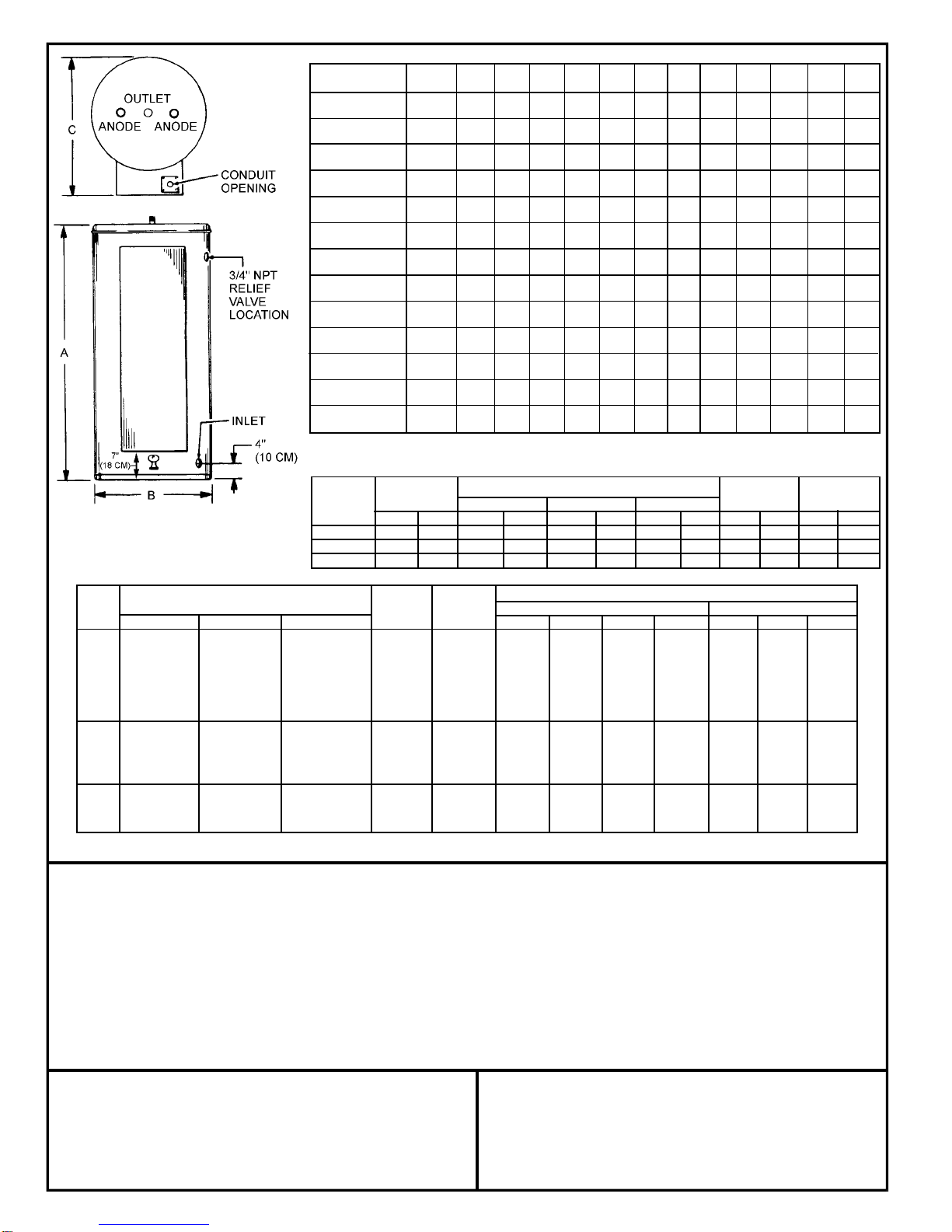
Tank Dimensions Inlet/ Approx. Ship.
Model Capacity A B C Outlet (NPT) Wt. (Lbs.)
Number gal. litre in. cm in. cm in. cm in. cm lb kg
DRE-52 50 189 55 1/4 140.3 21 3/4 55.2 27 1/4 69.2 1 1/4 3.2 265 120
DRE-80 80 300 59 1/2 151.1 25 1/4 64.1 31 1/4 79.4 1 1/4 3.2 280 127
DRE-120 119 450 62 1/4 158.1 29 1/2 75.0 35 3/4 90.8 1 1/4 3.2 390 177
Model Numbers Number Full Load Current In Amperes
KW Tank Capacity in Gallons Of Element Single Phase Three Phase
Input 50 80 119 Elements Wattage 208V 240V 277V 480V 208V 240V 480V
6 DRE-52-6 DRE-80-6 DRE-120-6 3 2,000 28.8 25.0 21.7 12.5 16.7 14.4 7.2
9 DRE-52-9 DRE-80-9 DRE-120-9 3 3,000 43.3 37.5 32.5 18.8 25.0 21.7 10.8
12 DRE-52-12 DRE-80-12 DRE-120-12 3 4,000 57.7 50.0 43.3 25.0 33.3 28.9 14.4
13.5 DRE-52-13.5 DRE-80-13.5 DRE-120-13.5 3 4,500 64.9 56.3 48.7 28.1 37.5 32.5 16.2
15 DRE-52-15 DRE-80-15 DRE-120-15 3 5,000 72.1 62.5 54.2 31.3 41.6 36.1 18.0
18 DRE-52-18 DRE-80-18 DRE-120-18 3* 6,000 86.5 75.0 65.0 37.5 50.0 43.3 21.7
24 DRE-52-24 DRE-80-24 DRE-120-24 6 4,000 115.4 100.0 86.6 50.0 66.6 57.7 28.9
27 DRE-52-27 DRE-80-27 DRE-120-27 6 4,500 129.8 112.5 97.5 56.3 74.9 65.0 32.5
30 DRE-52-30 DRE-80-30 DRE-120-30 6 5,000 144.2 125.0 108.3 62.5 83.3 72.2 36.1
36 DRE-52-36 DRE-80-36 DRE-120-36 6* 6,000 173.1 150.0 130.0 75.0 99.9 86.6 43.3
40.5 DRE-52-40.5 DRE-80-40.5 DRE-120-40.5 9 4,500 194.7 168.8 146.2 84.4 112.4 97.4 48.7
45 DRE-52-45 DRE-80-45 DRE-120-45 9 5,000 216.3 187.5 162.5 93.8 124.9 108.3 54.1
54 DRE-52-54 DRE-80-54 DRE-120-54 9 6,000 N/A 225.0 194.9 112.5 149.9 129.9 65.0
*208 volt models may contain three (3) additional elements.