AutomationDirect prosense SCU-2501 User manual

SCU-2501/
SCU-2502/
SCU-2503
Universal
Frequency
Converter
User Manual

2 SCU-2501 / SCU-2502 / SCU-2503
Universal frequency converter
SCU-2501 / SCU-2502 / SCU-2503
Table of contents
Warning ................................................................................................ 3
Symbol identification .................................................................................... 3
Safety instructions ...................................................................................... 3
Mounting / demounting the SCU-PDM1 or SCU-PDM2 ...................................................... 5
Functional highlights .................................................................................... 6
Applications ............................................................................................ 7
Connections ............................................................................................ 8
Block diagram........................................................................................... 10
Specifications........................................................................................... 11
Order................................................................................................... 11
Accessories............................................................................................. 11
Electrical specifications.................................................................................. 11
Programming ........................................................................................... 18
Configurable input error indication and input limits ........................................................ 18
Low cut-o function..................................................................................... 20
Square root function..................................................................................... 21
Relay functions ......................................................................................... 23
Setpoint and window configuration.................................................................... 23
Graphic depiction of relay action setpoint .............................................................. 23
Graphic depiction of relay action window............................................................... 24
Advanced settings menu................................................................................. 25
Routing diagram ........................................................................................ 29
Routing diagram, advanced settings (ADV.SET) ............................................................ 33
Routing diagram,
manual release of latched relays.......................................................................... 35
Help text overview...................................................................................... 36
Operation .............................................................................................. 38

SCU-2501 / SCU-2502 / SCU-2503 3
Warning
This device is designed for connection to hazardous electric voltages. Ignoring this warning can result in
severe personal injury or mechanical damage.
To avoid the risk of electric shock and fire, the safety instructions of this guide must be observed and
the guidelines followed. The specifications must not be exceeded, and the device must only be applied
as described in the following.
Prior to the commissioning of the device, this installation guide must be examined carefully.
Only qualified personnel (technicians) should install this device. If the equipment is used in a manner not
specified by the manufacturer, the protection provided by the equipment may be impaired.
Warning
Until the device is fixed, do not connect hazardous voltages to the device. The following operations
should only be carried out on a disconnected device and under ESD safe conditions:
General mounting, connection and disconnection of wires.
Troubleshooting the device.
Warning
Do not open the front plate of the device as this will cause damage to the connector for the SCU-PDM1
or SCU-PDM2 communication interfaces.
This device contains no DIP-switches or jumpers.
SCU-2501 / SCU-2502 / SCU-2503 must be mounted on a DIN rail according to DIN EN 60715.
Symbol identification
Triangle with an exclamation mark: Warning / demand. Potentially lethal situations. Read the manual
before installation and commissioning of the device in order to avoid incidents that could lead to
personal injury or mechanical damage.
The CE mark proves the compliance of the device with the essential requirements of the directives.
The double insulation symbol shows that the device is protected by double or reinforced insulation.
Safety instructions
Definitions
Hazardous voltages have been defined as the ranges: 75 to 1500 Volt DC, and 50 to 1000 Volt AC.
Technicians are qualified persons educated or trained to mount, operate, and also trouble-shoot technically correct and in
accordance with safety regulations.
Operators, being familiar with the contents of this manual, adjust and operate the knobs or potentiometers during normal
operation.
GENERAL
HAZARD-
OUS
VOLTAGE
CAUTION

4 SCU-2501 / SCU-2502 / SCU-2503
Receipt and unpacking
Unpack the device without damaging it and check whether the device type corresponds to the one ordered. The packing
should always follow the device until this has been permanently mounted.
Environment
Avoid direct sun light, dust, high temperatures, mechanical vibrations and shock, and rain and heavy moisture. If necessary,
heating in excess of the stated limits for ambient temperatures should be avoided by way of ventilation.
The device must be installed in pollution degree 2 or better.
The device is designed to be safe at least under an altitude up to 2,000 m.
The device is designed for indoor use.
Mounting
Only technicians, who are familiar with the technical terms, warnings, and instructions in the manual and who are able to
follow these, should connect the device. Should there be any doubt as to the correct handling of the device, please contact,
www.automationdirect.com
Mounting and connection of the device should comply with national legislation for mounting of electric materials, i.e. wire
cross section, protective fuse, and location.
Stranded wire should be installed with an insulation stripping length of 5 mm or via a suitable insulated terminal such as a
bootlace ferrule.
Descriptions of input / output and supply connections are shown in the block diagram and side label.
The following apply to fixed hazardous voltages-connected devices:
The max. size of the protective fuse is 10 A and, together with a power switch, it should be easily accessible and close
to the device. The power switch should be marked with a label indicating that it will switch off the voltage
to the device.
Year of manufacture can be taken from the first two digits in the serial number.
UL installation requirements
Use 60/75°C copper conductors only
For use only in pollution degree 2 or better
Max. ambient temperature . . . . . . . . . . . . . . . . . . . . . . . . . . . . . . 60°C
Max. wire size. . . . . . . . . . . . . . . . . . . . . . . . . . . . . . . . . . . . . . AWG 26-14
UL file number . . . . . . . . . . . . . . . . . . . . . . . . . . . . . . . . . . . . . E197592
Calibration and adjustment
During calibration and adjustment, the measuring and connection of external voltages must be carried out according to the
specifications of this manual. The technician must use tools and instruments that are safe to use.
Normal operation
Operators are only allowed to adjust and operate devices that are safely fixed in panels, etc., thus avoiding the danger of
personal injury and damage. This means there is no electrical shock hazard, and the device is easily accessible.
Cleaning
When disconnected, the device may be cleaned with a cloth moistened with distilled water.

OK
4501
1
3
4
2
3
4
SCU-2501 / SCU-2502 / SCU-2503 5
Mounting / demounting the SCU-PDM1 or SCU-PDM2
1: Insert the tabs of the SCU-PDM1 or SCU-PDM2 into the slots at the top of the device.
2: Hinge the SCU-PDM1 or SCU-PDM2 down until it snaps into place.
Demounting of the SCU-PDM1 or SCU-PDM2 communication interfaces
3: Push the release button on the bottom of the SCU-PDM1 or SCU-PDM2 and hinge the SCU-PDM1 or SCU-PDM2 out and up.
4: With the SCU-PDM1 or SCU-PDM2 hinged up, remove from the slots at the top of the device.

6 SCU-2501 / SCU-2502 / SCU-2503
Universal frequency converter
SCU-2501 / SCU-2502 / SCU-2503
• Front-programmable
• Input: NAMUR, NPN, PNP, Tacho, TTL & S0
• Output: Programmable bipolar mA / V, frequency or relay
• Universal power supply 21.6…253 VAC / 19.2...300 VDC
Functional highlights
• Measures frequencies up to 100 kHz.
• Active and passive current output ±23 mA / 0...23 mA.
• Buffered voltage output ±10 VDC.
• Linearization: Linear or square root function.
• 2-point process calibration.
• Programmable trigger levels -0.05…6.5 V.
• Programmable sensor supply 5…17 V.
• NAMUR sensor error detection.
• Advanced configurable input limits for increased safety.
• Digital output: NPN & PNP; 0...100 kHz with programmable logic level 5…24 V.
• Output relay with windows, setpoint and latch functionality.
• Simulation of process value during commissioning and maintenance.
• All terminals are over-voltage protected (24 VDC), polarity protected and short-circuit protected.
Technical highlights
• Accuracy < 0.06% / span.
• Temperature coefficient 0.006% / C°.
• Response time < 30 ms.
• 2.3 kVAC, 3-port galvanic isolation.
• NAMUR NE21 and NE43.
Programming
• Configuration, monitoring and diagnostics using the SCU-PDM1 or SCU-PDM2 detachable communication interfaces.
• All programming can be password-protected.
• Scrolling help text in 7 languages.
Mounting
• Units can be mounted side by side, horizontally and vertically, without air gap on a standard DIN rail – even at 60°C ambient
temperature.
24
23
22
21
44
43
42
41
S0
∼
TTL
-
+
-
+
-
+
(±)(±) -
+
-
+
(±)(±)
34
33
32
31
Tx
SCU-2501 / SCU-2502 / SCU-2503 7
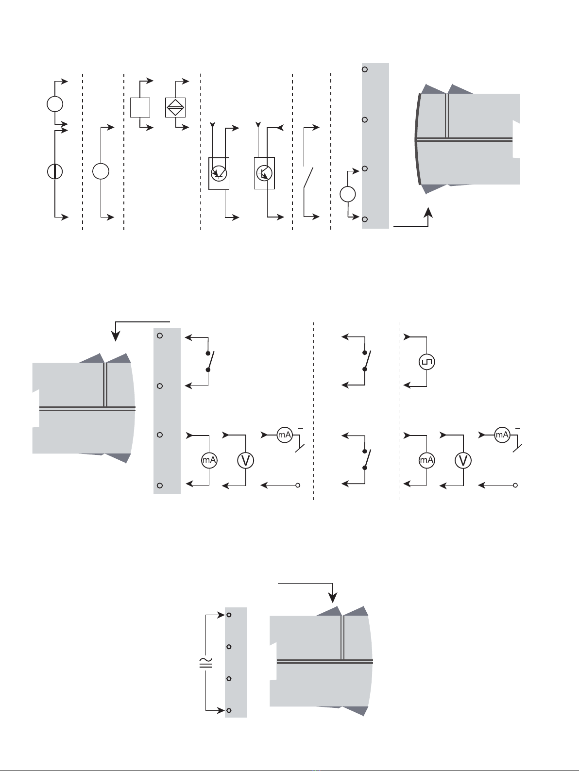
Applications
Power connection: 21.6...253 VAC
or
19.2...300 VDC
Output signals:
Input signals:
Contact
(NPN)
Special trig
current & voltage TTL S0 NAMUR PNP NPN Tacho
+ Supply + Supply
SCU-2502
Relays
SCU-2501
Analog, 0/4...20 mA,
voltage and relay
SCU-2503
Analog, 0/4...20 mA,
voltage and
frequency
Relay 2
Relay 1
+ V supply
3.5...28 V
2-wire 2-wire
+ V supply
3.5...28 V

8 SCU-2501 / SCU-2502 / SCU-2503
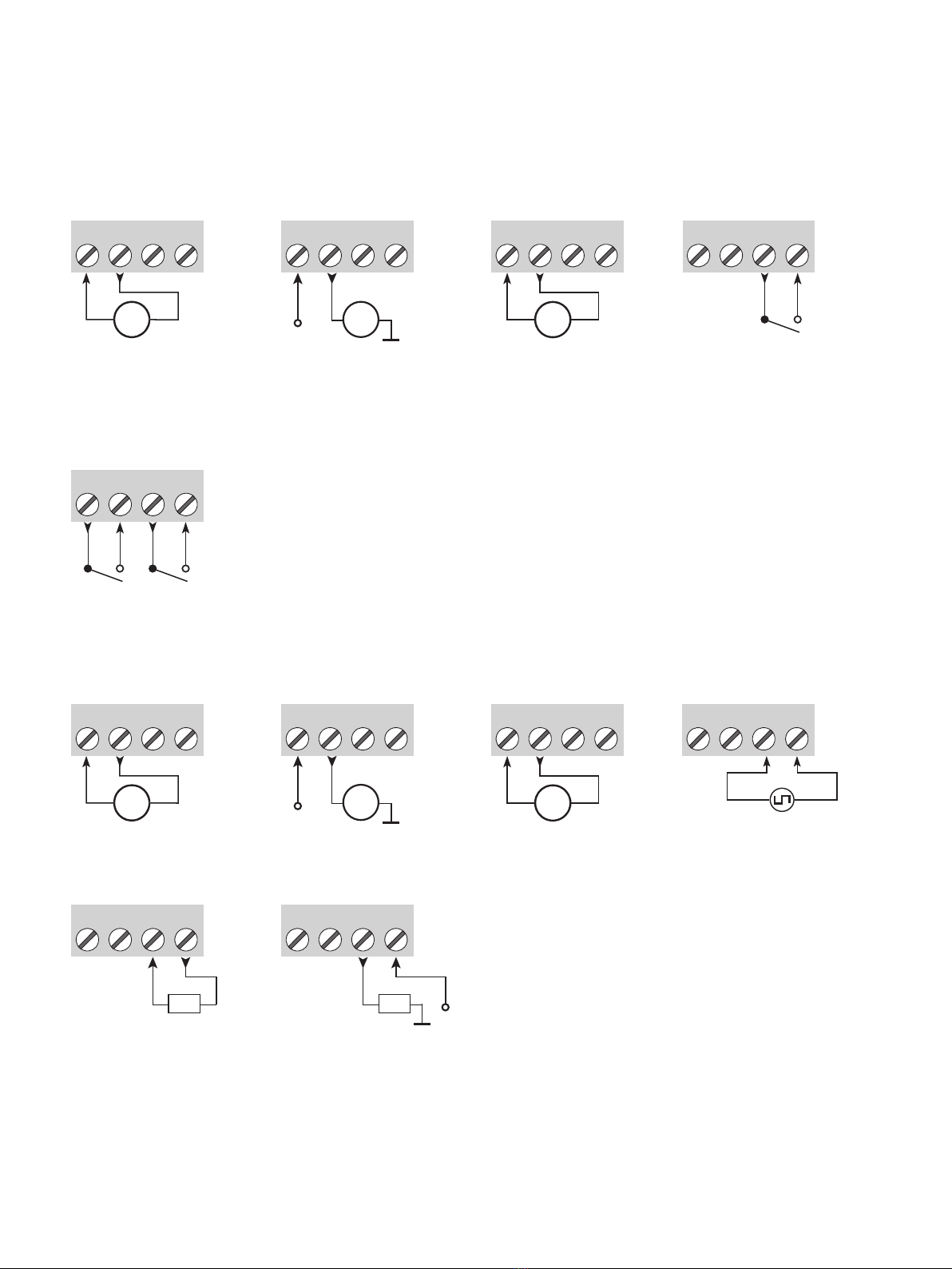
Connections
41 42 43 44
31 32 33 34
41 4342 44
41 4342 44
∼
Tx
41 42 44
43 41 4342 44
41 4342 44
+-
41 4342 44 41 42 44
43 41 4342 44
+
Inputs:
Supply
Special current Special voltage Tacho
PNP NPN Contact (NPN)
S0 TTLNAMUR
S0 TTL
+ supply 5...17 V+ supply 5...17 V
+ supply 5...17 V+ supply 5...17 V
+ supply + supply
+ supply 8.3 V + supply 17 V
SCU-2501 / SCU-2502 / SCU-2503 9
4225A
21 2322 2421 2322 24
+
-V
(±)
R2
21 22 23 24
+
-mA
(±)
21 2322 24
+mA -
+mA -
4225B
21 2322 24
R1 R2
21 2322 2421 2322 24
+
-V
(±)
21 22 23 24
+
-mA
(±)
21 2322 24
4225C
+
-
21 22 23 24 21 2322 24
Relays
Outputs:
Relay
2-wire transmitter
(Passive output)
Current
(Active output) Buered voltage
2-wire transmitter
(Passive output) Frequency
(Push / pull)
Current
(Active output)
Frequency
(NPN output)
Frequency
(PNP output)
Buered voltage
Rload
Rload
SCU-2501
SCU-2502
SCU-2503
Connections

10 SCU-2501 / SCU-2502 / SCU-2503
Block diagram
SCU-250x
44
43
42
41
24
21
22
34
31
23
fin
D /A
SCU-2501 / SCU-2503
SCU-2502
SCU-2501 / SCU-2502
SCU-2503
R1
+
R2
CPU
HW
Watchdog
*
VReg
5...17 V
21.6...253 VAC or
19.2...300 VDC
Green
Yellow
Yellow
VBuf
Yellow
Freq.
detector
/
CPU
* > 50 VDC isolation only valid for NPN output
Red
Rsense

SCU-2501 / SCU-2502 / SCU-2503 11
Accessories
SCU-PDM1 or SCU-PDM2 = Display / programming front
Note: The SCU-PDM1 or SCU-PDM2 communication interfaces are approved and certified as an add-on component to the SCU
series of devices. All technical characteristics are valid with the SCU-PDM1 or SCU-PDM2 communication interface attached.
Electrical specifications
Environmental conditions:
Operating temperature . . . . . . . . . . . . . . . . . . . . . . . . . . . . . . . . -20°C to +60°C
Storage temperature . . . . . . . . . . . . . . . . . . . . . . . . . . . . . . . . . -20°C to +85°C
Calibration temperature. . . . . . . . . . . . . . . . . . . . . . . . . . . . . . . . 20...28°C
Relative humidity . . . . . . . . . . . . . . . . . . . . . . . . . . . . . . . . . . . < 95% RH (non-cond.)
Protection degree . . . . . . . . . . . . . . . . . . . . . . . . . . . . . . . . . . . IP20
Installation in pollution degree 2 & measurement / overvoltage category II.
Mechanical specifications:
Dimensions (HxWxD) . . . . . . . . . . . . . . . . . . . . . . . . . . . . . . . . . 109 x 23.5 x 104 mm
Dimensions (HxWxD) w/ SCU-PDM1 or SCU-PDM2. . . . . . . . . . . . . . . . 109 x 23.5 x 116 / 131 mm (SCU-PDM1) or 144 mm
(SCU-PDM2) [4.3 x 0.9 x 4.6 / 5.2 in (SCU-PDM1) or
5.67 in. (SCU-PDM2) ]
Weight approx., SCU-2501 / SCU-2502 / SCU-2503 . . . . . . . . . . . . . . . 160 / 165 / 150 g
DIN rail type. . . . . . . . . . . . . . . . . . . . . . . . . . . . . . . . . . . . . . . DIN EN 60715 - 35 mm
Wire size. . . . . . . . . . . . . . . . . . . . . . . . . . . . . . . . . . . . . . . . . 0.13...2.08 mm2/ AWG 26...14 stranded wire
Screw terminal torque. . . . . . . . . . . . . . . . . . . . . . . . . . . . . . . . . 0.5 Nm
Common electrical specifications:
Supply voltage, universal. . . . . . . . . . . . . . . . . . . . . . . . . . . . . . . 21.6...253 VAC, 50...60 Hz
or 19.2...300 VDC
Protective fuse. . . . . . . . . . . . . . . . . . . . . . . . . . . . . . . . . . . . . 400 mA SB / 250 VAC
Max. required power. . . . . . . . . . . . . . . . . . . . . . . . . . . . . . . . . . ≤ 2.6 W
Max. power dissipation . . . . . . . . . . . . . . . . . . . . . . . . . . . . . . . . ≤ 2.1 W
Isolation voltage - test . . . . . . . . . . . . . . . . . . . . . . . . . . . . . . . . 2.3 kVAC
Isolation voltage - working
Input to any. . . . . . . . . . . . . . . . . . . . . . . . . . . . . . . . . . . . . . 250 VAC (reinforced)
Relay to relay, relay to analog . . . . . . . . . . . . . . . . . . . . . . . . . . . < 115 VAC (reinforced), > 115 VAC (basic)
NPN to analog . . . . . . . . . . . . . . . . . . . . . . . . . . . . . . . . . . . . Isolated > 50 VDC
Push-Pull / PNP to analog . . . . . . . . . . . . . . . . . . . . . . . . . . . . . Shared ground with analog output
Communications Interface . . . . . . . . . . . . . . . . . . . . . . . . . . . . . . Programming/display module, SCU-PDM2 (sold sepa-
rately) or SCU-PDM1 (discontinued and replaced by
SCU-PDM2)
Signal dynamics, output . . . . . . . . . . . . . . . . . . . . . . . . . . . . . . . 18 bit
Signal / noise ratio. . . . . . . . . . . . . . . . . . . . . . . . . . . . . . . . . . . > 60 dB
Response time (0...90%, 100...10%) . . . . . . . . . . . . . . . . . . . . . . . . ≤ 30 ms
Type Output
SCU-2501
SCU-2502
SCU-2503
1 analog output and 1 relay
2 relays
1 analog output and 1 frequency output
Order
Specifications
12 SCU-2501 / SCU-2502 / SCU-2503
Accuracy, the greater of basic and absolute values:
Input
Type Basic accuracy Absolute accuracy Temperature coecient
Frequency input ≤ 0.0002 Hz ≤ ±0.01% of input frequency ≤ ±0.0005% / °C
Output
Type Basic accuracy Absolute accuracy Temperature coecient
Current output 8 µA ≤ ±0.05% of span ≤ ±0.005% / 0.8 µA / °C
Voltage output 2 mV ≤ ±0.05% of span ≤ ±0.005% / 200 µV / °C
Frequency output n.a. ≤ ±0.002% of output frequency
+0.0004% of fmax.
≤ ±0.0005% / °C
EMC - immunity influence. . . . . . . . . . . . . . . . . . . . . . . . . . . . . . . . . . . . . . . . . . . . . . < ±0.5% of span
Extended EMC immunity:
NAMUR NE 21, A criterion, burst . . . . . . . . . . . . . . . . . . . . . . . . . . . . . . . . . . . . . . . . . < ±1% of span
of span = of selected standard range
Basic accuracyInput = 0.0002 Hz
Absolute accuracyInput = 0.001%
Calibration temperature= 20...28°C
Example 1: Analog current output, input low 1 kHz, input high 8 kHz, output span 4...20 mA = 16 mA:
AccuracyInput_low = 0.01% x 1000 Hz = 0.1 Hz
AccuracyInput_high = 0.01% x 8000 Hz = 0.8 Hz
AccuracyOutput = 0.05% x 7000 Hz = 3.5 Hz
Total accuracyLow = AccuracyInput_low + AccuracyOutput
Total accuracyLow = 0.1 Hz + 3.5 Hz = 3.6 Hz
Total accuracyHigh = AccuracyInput_high + AccuracyOutput
Total accuracyHigh = 0.8 Hz + 3.5 Hz = 4.3 Hz
Example accuracy calculations are based on factory calibration ambient temperature, and do not take into account other
potential sources of inaccuracy, e.g. power supply eect, ambient temperature fluctuation etc. which must also be considered.

SCU-2501 / SCU-2502 / SCU-2503 13
Auxiliary supplies
Sensor supply limitation (terminal 44) . . . . . . . . . . . . . . . . . . . . . . . 20 mA, 5…17 V
Input specifications
Frequency input
Frequency range . . . . . . . . . . . . . . . . . . . . . . . . . . . . . . . . . . . . 0.001 Hz to 100 kHz
Time range, time function . . . . . . . . . . . . . . . . . . . . . . . . . . . . . . 10 µs to 999.9 s
Max. frequency, with input filter ON . . . . . . . . . . . . . . . . . . . . . . . . 75 Hz
Min. pulse width with input filter ON. . . . . . . . . . . . . . . . . . . . . . . . 8 ms
Min. pulse width with input filter OFF . . . . . . . . . . . . . . . . . . . . . . . 4 µs
Response time (0...90%, 100...10%) . . . . . . . . . . . . . . . . . . . . . . . . < 30 ms
NAMUR input
Trig-level LOW . . . . . . . . . . . . . . . . . . . . . . . . . . . . . . . . . . . . . ≤ 1.2 mA
Trig-level HIGH . . . . . . . . . . . . . . . . . . . . . . . . . . . . . . . . . . . . . ≥ 2.1 mA
Input impedance . . . . . . . . . . . . . . . . . . . . . . . . . . . . . . . . . . . . 1 kΩ || < 220 pF
Breakage detection . . . . . . . . . . . . . . . . . . . . . . . . . . . . . . . . . . ≤ 0.1 mA
Short-circuit detection . . . . . . . . . . . . . . . . . . . . . . . . . . . . . . . . ≥ 6.9 mA
Sensor supply - pin 44, fixed. . . . . . . . . . . . . . . . . . . . . . . . . . . . . 8.3 V
Tacho input
Trig-level LOW . . . . . . . . . . . . . . . . . . . . . . . . . . . . . . . . . . . . . ≤ -50 mV
Trig-level HIGH . . . . . . . . . . . . . . . . . . . . . . . . . . . . . . . . . . . . . ≥ +50 mV
Input impedance . . . . . . . . . . . . . . . . . . . . . . . . . . . . . . . . . . . . 100 kΩ || < 220 pF
Max. input voltage. . . . . . . . . . . . . . . . . . . . . . . . . . . . . . . . . . . 80 VAC pp
Sensor supply - pin 44, programmable . . . . . . . . . . . . . . . . . . . . . . . 5...17 V / 23 mA
NPN / PNP input
Trig-level LOW . . . . . . . . . . . . . . . . . . . . . . . . . . . . . . . . . . . . . ≤ 4.0 V
Trig-level HIGH . . . . . . . . . . . . . . . . . . . . . . . . . . . . . . . . . . . . . ≥ 7.0 V
Input impedance . . . . . . . . . . . . . . . . . . . . . . . . . . . . . . . . . . . . 3.48 kΩ || < 220 pF
Trigger edge . . . . . . . . . . . . . . . . . . . . . . . . . . . . . . . . . . . . . . NPN = Neg. edge, PNP = Pos. edge.
Sensor supply - pin 44, programmable . . . . . . . . . . . . . . . . . . . . . . . 5...17 V / 23 mA
TTL input
Trig-level LOW . . . . . . . . . . . . . . . . . . . . . . . . . . . . . . . . . . . . . ≤ 0.8 V
Trig-level HIGH . . . . . . . . . . . . . . . . . . . . . . . . . . . . . . . . . . . . . ≥ 2.0 V
Input impedance . . . . . . . . . . . . . . . . . . . . . . . . . . . . . . . . . . . . ≥ 100 kΩ || < 220 pF
Sensor supply - pin 44, programmable . . . . . . . . . . . . . . . . . . . . . . . 5...17 V / 23 mA
S0 input
Trig-level LOW . . . . . . . . . . . . . . . . . . . . . . . . . . . . . . . . . . . . . ≤ 2.2 mA
Trig-level HIGH . . . . . . . . . . . . . . . . . . . . . . . . . . . . . . . . . . . . . ≥ 9.0 mA
Input impedance . . . . . . . . . . . . . . . . . . . . . . . . . . . . . . . . . . . . 758 Ω || < 220 pF
Sensor supply - pin 44, fixed. . . . . . . . . . . . . . . . . . . . . . . . . . . . . 17 V

14 SCU-2501 / SCU-2502 / SCU-2503
Special voltage input
User-programmable trig-levels. . . . . . . . . . . . . . . . . . . . . . . . . . . . -0.05...6.50 V
*Hysteresis, min.. . . . . . . . . . . . . . . . . . . . . . . . . . . . . . . . . . . . 50 mV
Input impedance, programmable:
High Z . . . . . . . . . . . . . . . . . . . . . . . . . . . . . . . . . . . . . . . . . ≥100 kΩ || < 220 pF
Pull up/down . . . . . . . . . . . . . . . . . . . . . . . . . . . . . . . . . . . . . 3.48 kΩ || < 220 pF
Programmable sensor supply - pin 44 . . . . . . . . . . . . . . . . . . . . . . . 5...17 V / 23 mA
Max. input voltage. . . . . . . . . . . . . . . . . . . . . . . . . . . . . . . . . . . 17 V
Special current input
User-programmable trig-levels. . . . . . . . . . . . . . . . . . . . . . . . . . . . 0.0...10.0 mA
*Hysteresis, min.. . . . . . . . . . . . . . . . . . . . . . . . . . . . . . . . . . . . 0.2 mA
Input impedance . . . . . . . . . . . . . . . . . . . . . . . . . . . . . . . . . . . . 1 kΩ || < 220 pF
Sensor supply - pin 44, programmable . . . . . . . . . . . . . . . . . . . . . . . 5...17 V / 23 mA
Max. input current . . . . . . . . . . . . . . . . . . . . . . . . . . . . . . . . . . . 17 mA
* For low signal levels with input trigger level hysteresis below 100 mV / 0.1 mA it is recommended to use shielded cables with
correct grounding, to avoid false triggering due to induced EMC.
Configurable input limits
Error detection . . . . . . . . . . . . . . . . . . . . . . . . . . . . . . . . . . . . . Enable / disable
Configurable input limits, low . . . . . . . . . . . . . . . . . . . . . . . . . . . . 0 Hz…min. configured input frequency
Configurable input limits, high. . . . . . . . . . . . . . . . . . . . . . . . . . . . Max. configured input frequency…100 kHz
Hysteresis. . . . . . . . . . . . . . . . . . . . . . . . . . . . . . . . . . . . . . . . 0.5% of max. configured input frequency
Input limit low/high, error indication levels . . . . . . . . . . . . . . . . . . . . UP, DOWN, ZERO, NONE
See tables on pages 19-20
Output specifications
Current output
All standard ranges can be selected as Direct or Inverted action.
Signal range, active / passive . . . . . . . . . . . . . . . . . . . . . . . . . . . . ±23 mA / 0...23 mA
Programmable standard ranges . . . . . . . . . . . . . . . . . . . . . . . . . . . 0...20, 4...20, S4-20, ±10 mA, ±20 mA
Load, max.. . . . . . . . . . . . . . . . . . . . . . . . . . . . . . . . . . . . . . . . ±23 mA / 600 Ω / ±13.8 VDC
External 2-wire loop supply . . . . . . . . . . . . . . . . . . . . . . . . . . . . . 3.5...28 V
Response time, programmable. . . . . . . . . . . . . . . . . . . . . . . . . . . . 0...60 s
Load stability . . . . . . . . . . . . . . . . . . . . . . . . . . . . . . . . . . . . . . ≤ 0.001% of span / 100 Ω
Sensor error indication . . . . . . . . . . . . . . . . . . . . . . . . . . . . . . . . 0 / 3.5 / 23 mA / none
Output limitation at outside range . . . . . . . . . . . . . . . . . . . . . . . . . See tables on pages 19-20
Current limit. . . . . . . . . . . . . . . . . . . . . . . . . . . . . . . . . . . . . . . ≤ 28 mA
Buffered voltage output
All standard ranges can be selected as Direct or Inverted action
Signal range. . . . . . . . . . . . . . . . . . . . . . . . . . . . . . . . . . . . . . . ±11.5 VDC
Programmable standard ranges . . . . . . . . . . . . . . . . . . . . . . . . . . . 0…5, 1…5, 0...10, 2…10, ±5, ±10 VDC
Load, min. . . . . . . . . . . . . . . . . . . . . . . . . . . . . . . . . . . . . . . . . > 2 kΩ
Response time, programmable. . . . . . . . . . . . . . . . . . . . . . . . . . . . 0...60 s
Output limitation at outside range . . . . . . . . . . . . . . . . . . . . . . . . . See tables on pages 19-20
0,10 A
1,00 A
0 V 50 V 100 V 150 V 200 V 250 V
CURRENT
U
RELAY
SCU-2501 / SCU-2502 / SCU-2503 15
Relay outputs
Relay functions. . . . . . . . . . . . . . . . . . . . . . . . . . . . . . . . . . . . . Setpoint, Window, Sensor error, Latch, Power and O
Hysteresis. . . . . . . . . . . . . . . . . . . . . . . . . . . . . . . . . . . . . . . . 0...100%
On and O delay . . . . . . . . . . . . . . . . . . . . . . . . . . . . . . . . . . . . 0...3600 s
Power on delay. . . . . . . . . . . . . . . . . . . . . . . . . . . . . . . . . . . . . 0...9999 s
NAMUR sensor error detection . . . . . . . . . . . . . . . . . . . . . . . . . . . Break / Make / Hold
Max. voltage . . . . . . . . . . . . . . . . . . . . . . . . . . . . . . . . . . . . . . 250 VAC / VDC
Max. AC current. . . . . . . . . . . . . . . . . . . . . . . . . . . . . . . . . . . . . 2 A
Max. AC power . . . . . . . . . . . . . . . . . . . . . . . . . . . . . . . . . . . . . 500 VA
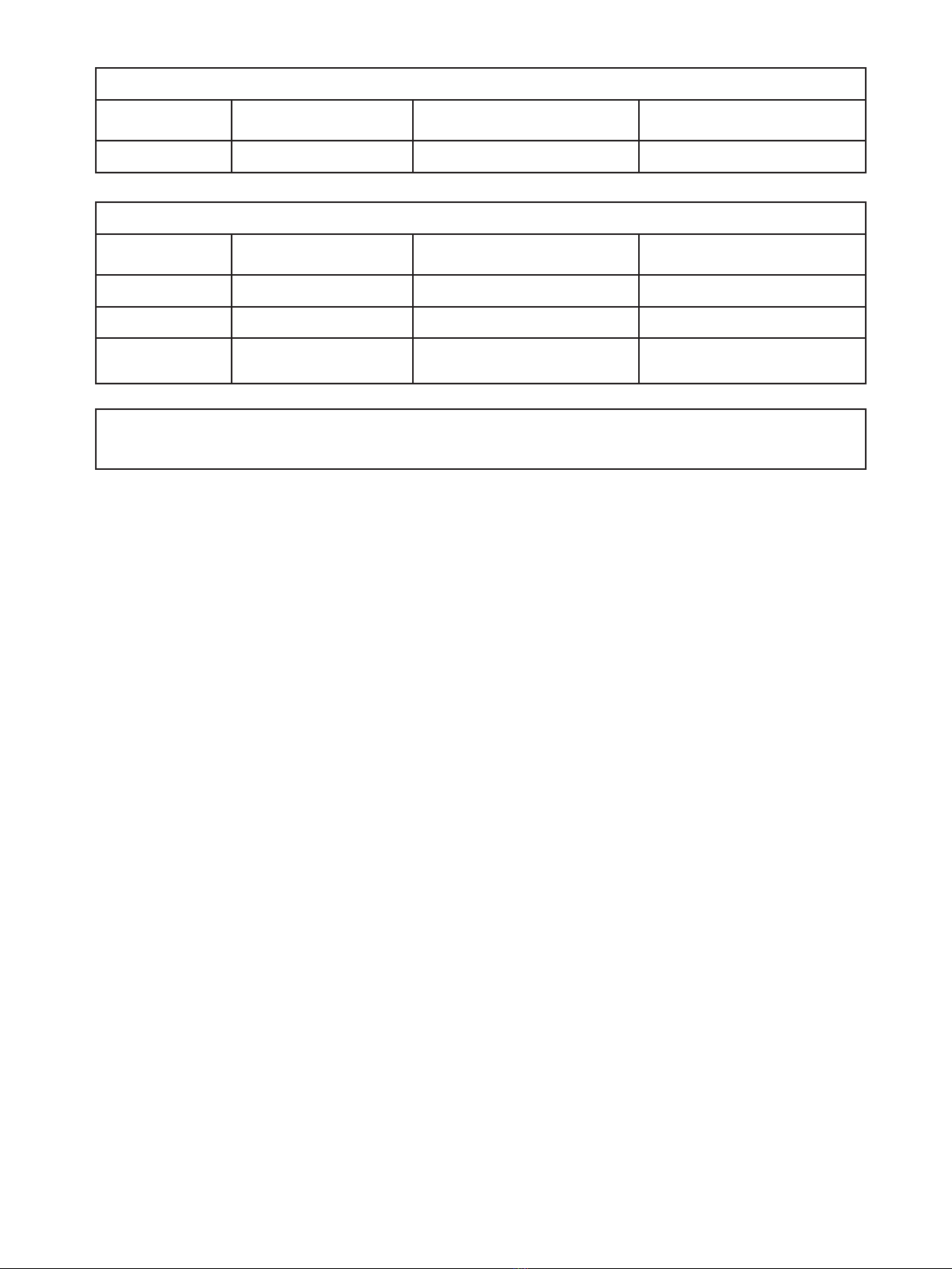
Max. DC current, resistive load:
@ Urelay ≤ 30 VDC . . . . . . . . . . . . . . . . . . . . . . . . . . . . . . . . . . 2 ADC
@ Urelay >30 VDC. . . . . . . . . . . . . . . . . . . . . . . . . . . . . . . . . . . [1380 x U-2
relayx 1.0085Urelay] ADC
Graphic depiction of [1380 x U-2
relayx 1.0085Urelay]:
Frequency output
Frequency range . . . . . . . . . . . . . . . . . . . . . . . . . . . . . . . . . . . . 0.001 Hz...100 kHz
Duty cycle f ≤ 500 Hz . . . . . . . . . . . . . . . . . . . . . . . . . . . . . . . . . < 90%
Programmable pulse time (f ≤ 500 Hz). . . . . . . . . . . . . . . . . . . . . . . 1…1000 ms
Pulse time > 500 Hz. . . . . . . . . . . . . . . . . . . . . . . . . . . . . . . . . . Fixed 50%
PNP output
**Isource max. . . . . . . . . . . . . . . . . . . . . . . . . . . . . . . . . . . . . . 30 mA
Vout . . . . . . . . . . . . . . . . . . . . . . . . . . . . . . . . . . . . . . . . . . . 24 VDC ± 10%
Cout. . . . . . . . . . . . . . . . . . . . . . . . . . . . . . . . . . . . . . . . . . . . 10 nF
Rout typ.. . . . . . . . . . . . . . . . . . . . . . . . . . . . . . . . . . . . . . . . . 30 Ω
NPN output
Isink max. . . . . . . . . . . . . . . . . . . . . . . . . . . . . . . . . . . . . . . . . 130 mA
Isink max. peak . . . . . . . . . . . . . . . . . . . . . . . . . . . . . . . . . . . . . 500 mA
Voltage drop 130 mA . . . . . . . . . . . . . . . . . . . . . . . . . . . . . . . . . < 1.5 VDC
External voltage (terminal 24) max. . . . . . . . . . . . . . . . . . . . . . . . . 30 VDC
Cout. . . . . . . . . . . . . . . . . . . . . . . . . . . . . . . . . . . . . . . . . . . . 10 nF
Rout typ. . . . . . . . . . . . . . . . . . . . . . . . . . . . . . . . . . . . . . . . . 10 Ω
Push-Pull output
Voltage . . . . . . . . . . . . . . . . . . . . . . . . . . . . . . . . . . . . . . . . . 5…24 VDC
Urelay
50 V 150 V0 V 100 V 200 V 250 V
Current
0.10 A
0.40 A
0.80 A
0.20 A
1.00 A
0.60 A
2.00 A
3.00 A

16 SCU-2501 / SCU-2502 / SCU-2503
**Power output limitations - SCU-2503
Power limitations when using buffered voltage output (SCU-2503 only)
600500400300200100 700 800 900
400
300
200
100
500
Sensor supply output power
Digital output power
Correct
operating range
Overpower
condition
mW
560 mW
mW
Power limitations when using current output with 10 mA maximum output (SCU-2503 only)
600500400300200100 700 800 900
400
300
200
100
500
Sensor supply output power
Digital output power
Correct
operating range
Overpower
condition
mW
460 mW
mW
Power limitations when using current output with 20 mA maximum output (SCU-2503 only)
600500400300200100 700 800 900
400
300
200
100
500
Sensor supply output power
Digital output power
Correct
operating range
Overpower
condition
mW
260 mW
mW

SCU-2501 / SCU-2502 / SCU-2503 17
Supported output configurations
For the SCU-2501 / SCU-2502 a concurrent and independent operation of analog output and relay is possible. For SCU-2503
the output is either presented on the analog or frequency output. In case of SCU-2503 being configured for analog output, the
frequency output can be configured for ‘relay mode’.
When both analog and frequency output is used, and frequency output is configured for PNP or push-pull, a common ground
is not possible for terminal 21 and 23.
Observed authority requirements
EMC. . . . . . . . . . . . . . . . . . . . . . . . . . . . . . . . . . . . . . . . . . . . 2014/30/EU
LVD . . . . . . . . . . . . . . . . . . . . . . . . . . . . . . . . . . . . . . . . . . . . 2014/35/EU
RoHS . . . . . . . . . . . . . . . . . . . . . . . . . . . . . . . . . . . . . . . . . . . 2011/65/EU
Approvals
c UL us, UL 508. . . . . . . . . . . . . . . . . . . . . . . . . . . . . . . . . . . . . E197592
18 SCU-2501 / SCU-2502 / SCU-2503
Programming
The SCU-PDM1 or SCU-PDM2 communication interfaces provide complete module programming and access to a wide range of
operational features that help you when using the device.
This chapter deals with the SCU-2501 / SCU-2502 / SCU-2503 advanced features. The complete menu structure and
programming options can be found in the Routing diagram section.
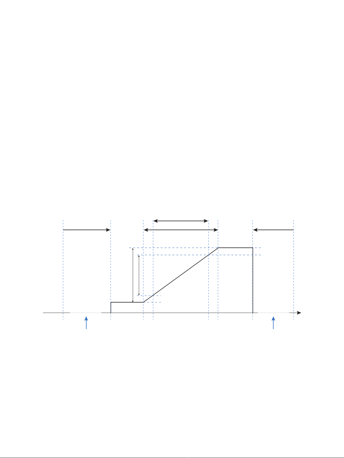
Configurable input error indication and input limits
Configurable input error detection
To increase system safety and integrity, you can program a high and low input error detection level. Input signals outside the
low and high limits will cause the output of the device to go to the programmed error state.
The two configurable input error detection levels can be set and enabled individually, just as it is possible to individually set
the output error indication for each of the two detection levels. This allows users to differentiate process faults, broken or
short input wires.
Available output error states for low and high limit: UP, DOWN, ZERO and NONE.
Output error indication uses the error states defined by NAMUR NE43 for a 4...20 mA output. For all other output spans
equivalent output error indications are used (see tables on pages 19-20).
When input limit is enabled and error state NONE is selected, the input error is detected and presented to you on the display
with IN.ER and flashing display, but not indicated on the output signal.
Example – 4...20 mA output span and both Limit high and Limit low set to ZERO
Device
Min. input Configurable input
limit, low Configurable input
limit, high Device
Max. input
Error frequency Error frequency Input:
Hz
Normal measuring range
Output error indication = ZERO
Extended measuring range
20.0 mA
4.0 mA
20.5 mA
3.8 mA
Normal range
Extended working range
Output error current can be
individually set to:
ZERO: 0 mA
UP: 23 mA
DOWN: 3.5 mA
NONE: No error indication,
output limited to 3.8 mA
Output error current can be
individually set to:
ZERO: 0 mA
UP: 23 mA
DOWN: 3.5 mA
NONE: No error indication,
output limited to 20.5 mA
SCU-2501 / SCU-2502 / SCU-2503 19
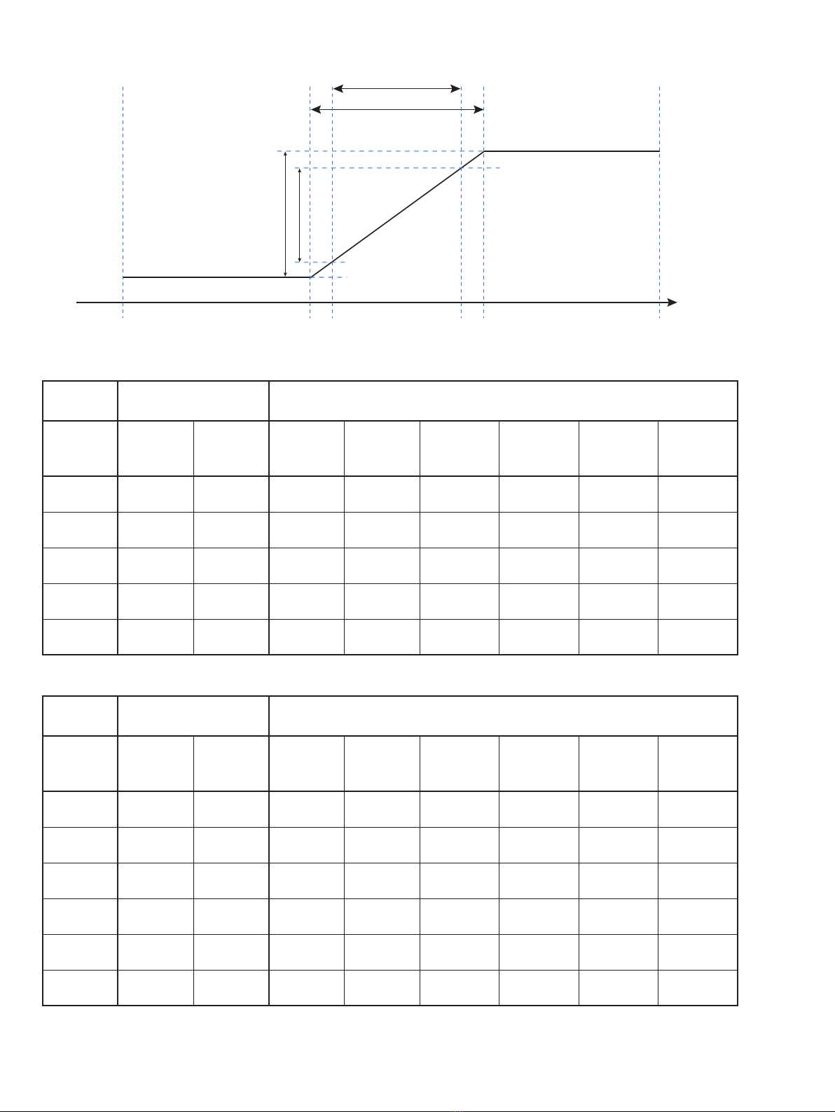
Example – Input limits disabled
‘Min. selected
input’ - 15% ‘Max. selected
input’ + 15%
Normal measuring range
Output error indication = NONE
Extended measuring range
20.0 mA
4.0 mA
3.8 mA
Normal range
Extended working range
20.5 mA
Input:
Hz
Output limits and error indications – current output
Input limit disabled NAMUR sensor error detection / input limit enabled
Output
span Output limit
low Output limit
high Output limit
low Output limit
high
Output error
indication,
UP
Output error
indication,
DOWN
Output error
indication,
ZERO
Output error
indication,
NONE
4-20 mA 0 mA 23 mA 3.8 mA 20.5 mA 23 mA 3.5 mA 0 mA No error
indication
S4-20 mA 0 mA 23 mA 3.8 mA 20.5 mA 23 mA 3.5 mA 0 mA No error
indication
0-20 mA 0 mA 23 mA 0 mA 20.5 mA 23 mA 0 mA 0 mA No error
indication
±10 mA -11.5 mA 11.5 mA -10.25 mA 10.25 mA 11.5 mA -11.5 mA 0 mA No error
indication
±20 mA -23 mA 23 mA -20.5 mA 20.5mA 23 mA -23 mA 0 mA No error
indication
Output limits and error indications – voltage output
Input limit disabled NAMUR sensor error detection / input limit enabled
Output
span Output limit
low Output limit
high Output limit
low Output limit
high
Output error
indication,
UP
Output error
indication,
DOWN
Output error
indication,
ZERO
Output error
indication,
NONE
0-5 V 0 V 5.75 V 0 V 5.125 V 5.75 V 0 V 0 V No error
indication
1-5 V 0 V 5.75 V 0.975 V 5.125 V 5.75 V 0.875 V 0 V No error
indication
0-10 V 0 V 11.5 V 0 V 10.25 V 11.5 V 0 V 0 V No error
indication
2-10 V 0 V 11.5 V 1.95 V 10.25 V 11.5 V 1.75 V 0 V No error
indication
±5 V -5.75 V 5.75 V -5.125 V 5.125 V 5.75 V -5.75 V 0 V No error
indication
±10 V -11.5 V 11.5 V -10.25 V 10.25 V 11.5 V -11. 5V 0 V No error
indication
20 SCU-2501 / SCU-2502 / SCU-2503
Output limits and error indications – custom frequency output, 50% duty cycle
Input limit disabled NAMUR sensor error detection / input limit enabled
Output span Output limit
low Output limit
high Output limit
low Output limit
high
Output error
indication,
UP / DOWN
Output error
indication,
NONE
Output low = 0 0 Hz Output High *
700%, cap at
115 kHz 0 Hz Output high *
102.5% Customer
configurable No error
indication
Output low > 0 0 Hz Output High *
700%, cap at
115 kHz
Output low *
95% Output high *
102.5% Customer
configurable No error
indication
Output limits and error indications – custom frequency output, configurable duty cycle
Input limit disabled NAMUR sensor error detection / input limit enabled
Output span Output limit
low Output limit
high Output limit
low Output limit
high
Output error
indication,
UP / DOWN
Output error
indication,
NONE
Output low = 0 0 Hz ‘Max Output’ *
105%. 0 Hz Output high *
102.5% Customer
configurable No error
indication
Output low > 0 0 Hz ‘Max Output’ *
105%. Output low *
95% Output high *
102.5% Customer
configurable No error
indication
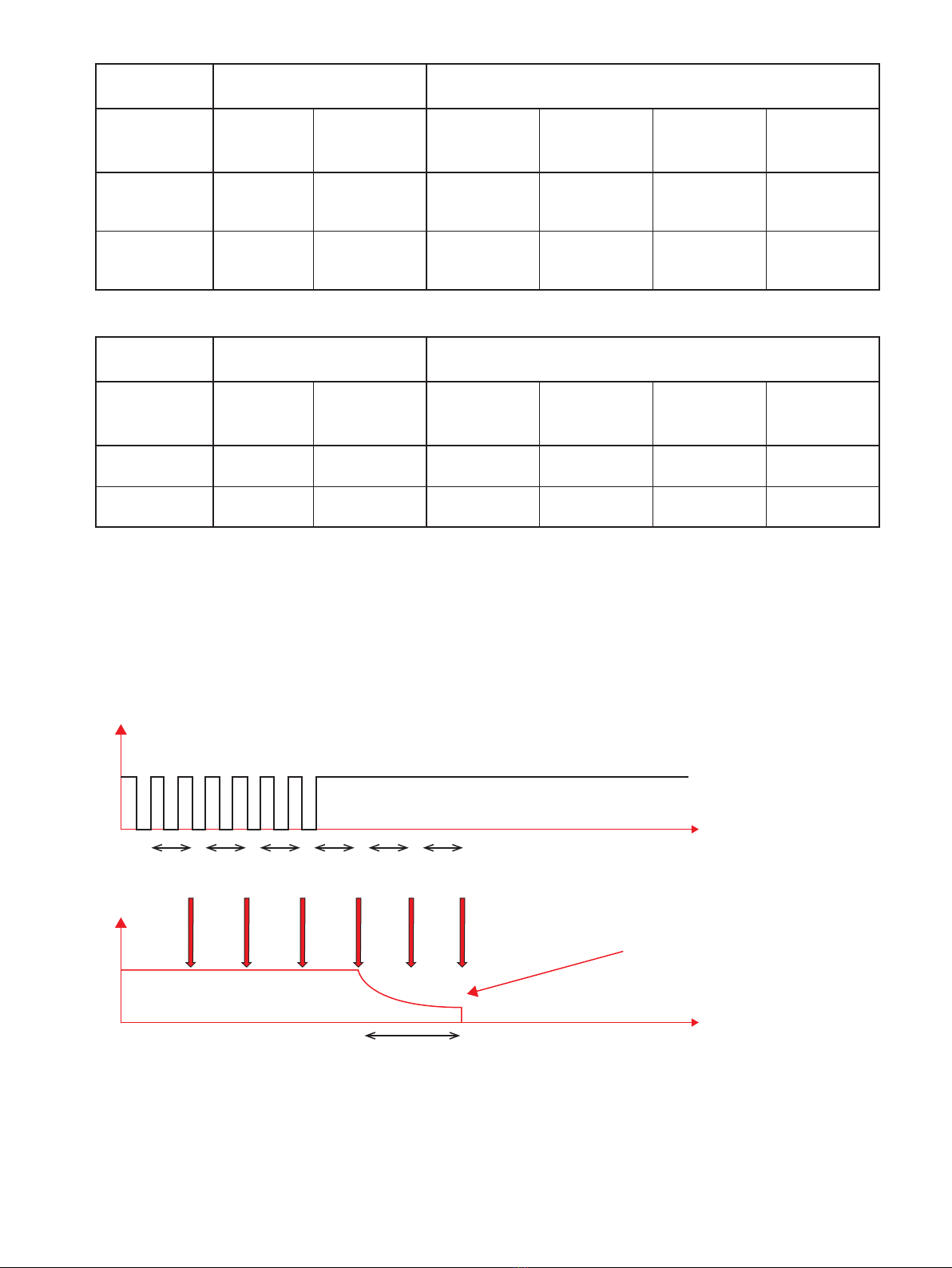
Low cut-off function
Default configured for 1111 s (0.0009 Hz) or 2 s (0.5 Hz) with L.COF enabled. Drives input to 0 Hz when Low Cut-Off time is
reached.
For the frequency output of SCU-2503, an output low cut-off can be configured independently of the input low cut-off.
The LO.CUT point can be configured between output low and output hi frequency.
Input
Analog
output Output
update
Time
Time
8 ms 8 ms 8 ms 8 ms 8 ms 8 ms
1111 s or 2 s
Input low cut-o.
Default congured for 1111 s (0.0009 Hz) or
2 s (0.5 Hz) with L.COF enabled.
This manual suits for next models
2
Table of contents
Other AutomationDirect Media Converter manuals


