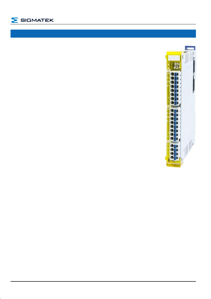
SSI 021 S-DIAS SAFETY SSI ABSOLUTE ENCODER
Page 2 25.04.2022
Contents
1Basic Safety Guidelines......................................................... 4
1.1 General Information on Safety ....................................................4
1.2 Further Safety Guidelines............................................................5
1.3 General Requirements .................................................................6
2Safety Conformity................................................................... 9
2.1 Functional Safety Standards.......................................................9
2.2 EU Conformity Declaration..........................................................9
2.3 Safety-Relevant Parameters......................................................10
2.3.1 Mounting Position Horizontal 0-55 °C Ambient Temperature ............10
2.3.2 Mounting Position Horizontal 0-60 °C Ambient Temperature ............10
2.4 Compatibility...............................................................................11
3Technical Data .......................................................................12
3.1 SSI Encoder Specifications.......................................................12
3.2 Electrical Requirements.............................................................13
3.3 Miscellaneous .............................................................................16
3.4 Environmental Conditions.........................................................16
4Mechanical Dimensions........................................................17
5Connector Layout..................................................................18
5.1 Status LEDs.................................................................................19
5.2 Applicable Connectors...............................................................19
5.3 Label Field...................................................................................20


