01
www.a4.fr
Product Presentation
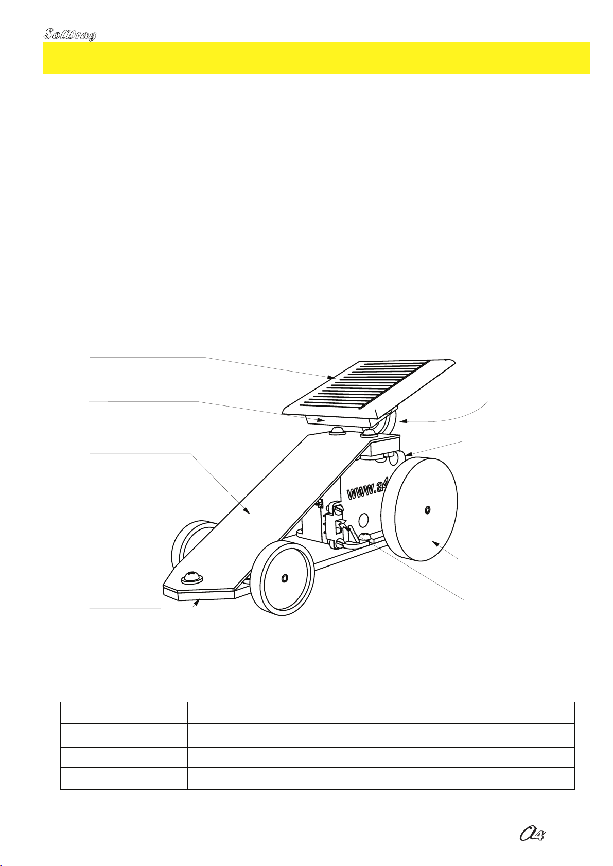
Soldrag vehicle photovoltaic cell:
Function
Manufacturing
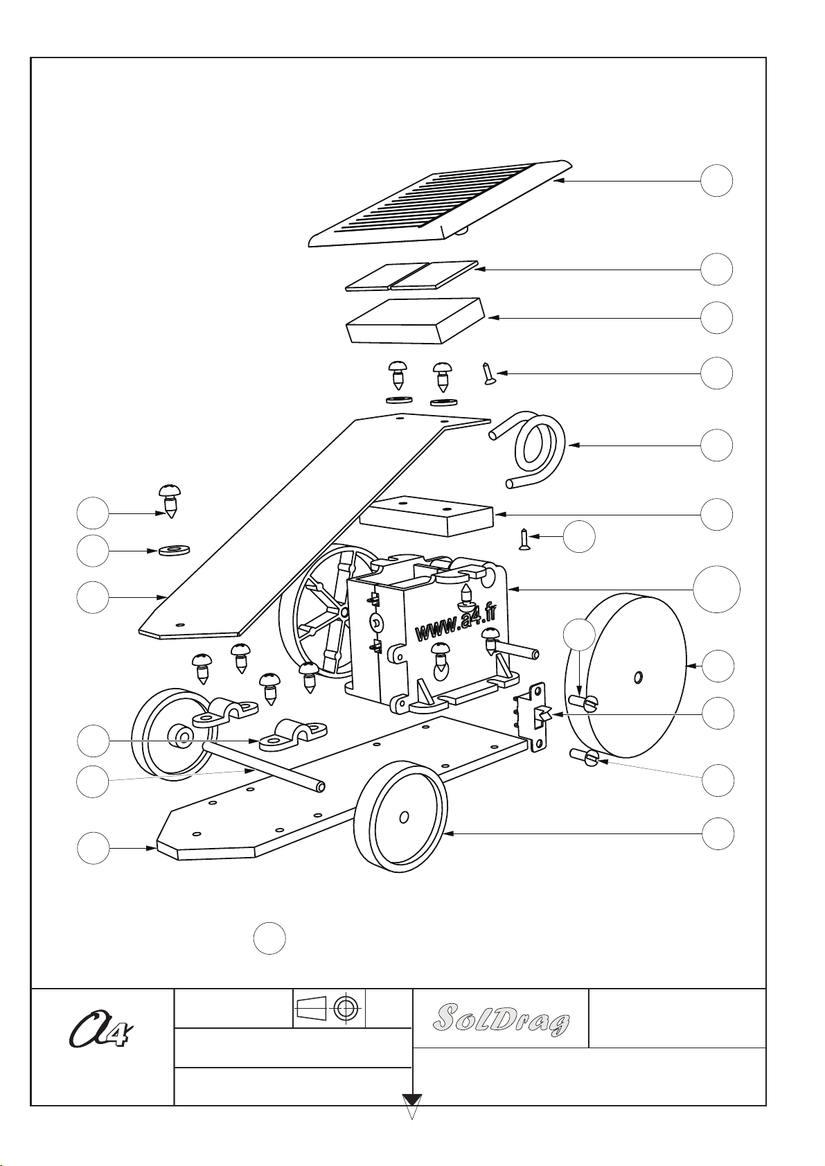
Kit
Cell support
Photovoltaic cell
Gear motor
Chassis
Driving wheel
Flexible aluminium wire
Bonnet
On/Off command
Technology Efficiency Cost Use
Monocristalline cells 24% High
Polycristalline cells 18.6%
12.7%
Average
Amorphous cells Low
Aerospace
Home
Consumer products
Electric vehicle powered by solar energy.
Only operates in direct sunlight (unless using the super capacity capacitor) or an incandescent lamp. Under tungsten or
halogen lighting, a minimum of 300 W at 20 cm from the photovoltaic cell is required for an equivalent efficiency. A
fluorescent tube lighting (neon) does not allow the photovoltaic cell to power the motor.
The photovoltaic cell assembled on a flexible wire is adaptable to capture the light more easily.
There is the option of a 10 F super capacity capacitor which can be assembled to store energy, thus allowing a few
minutes of operation without direct lighting.
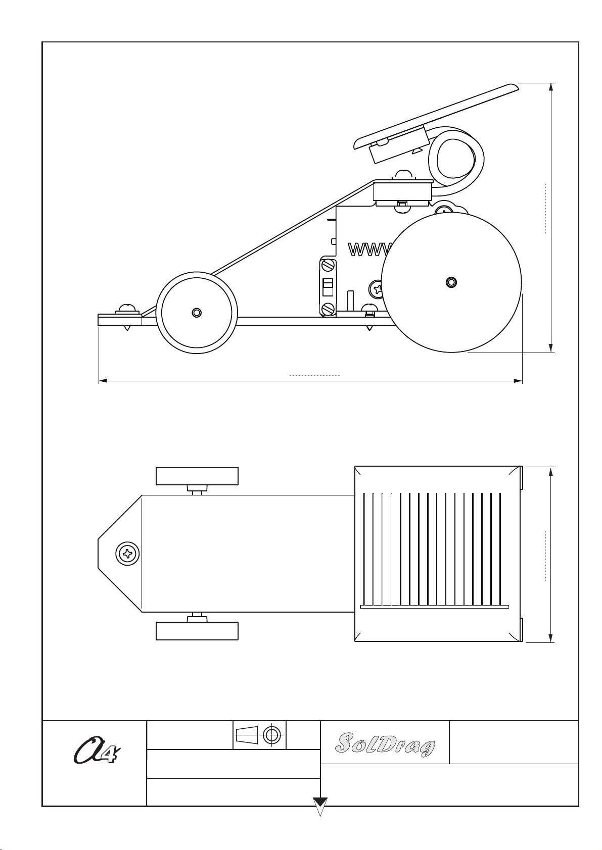
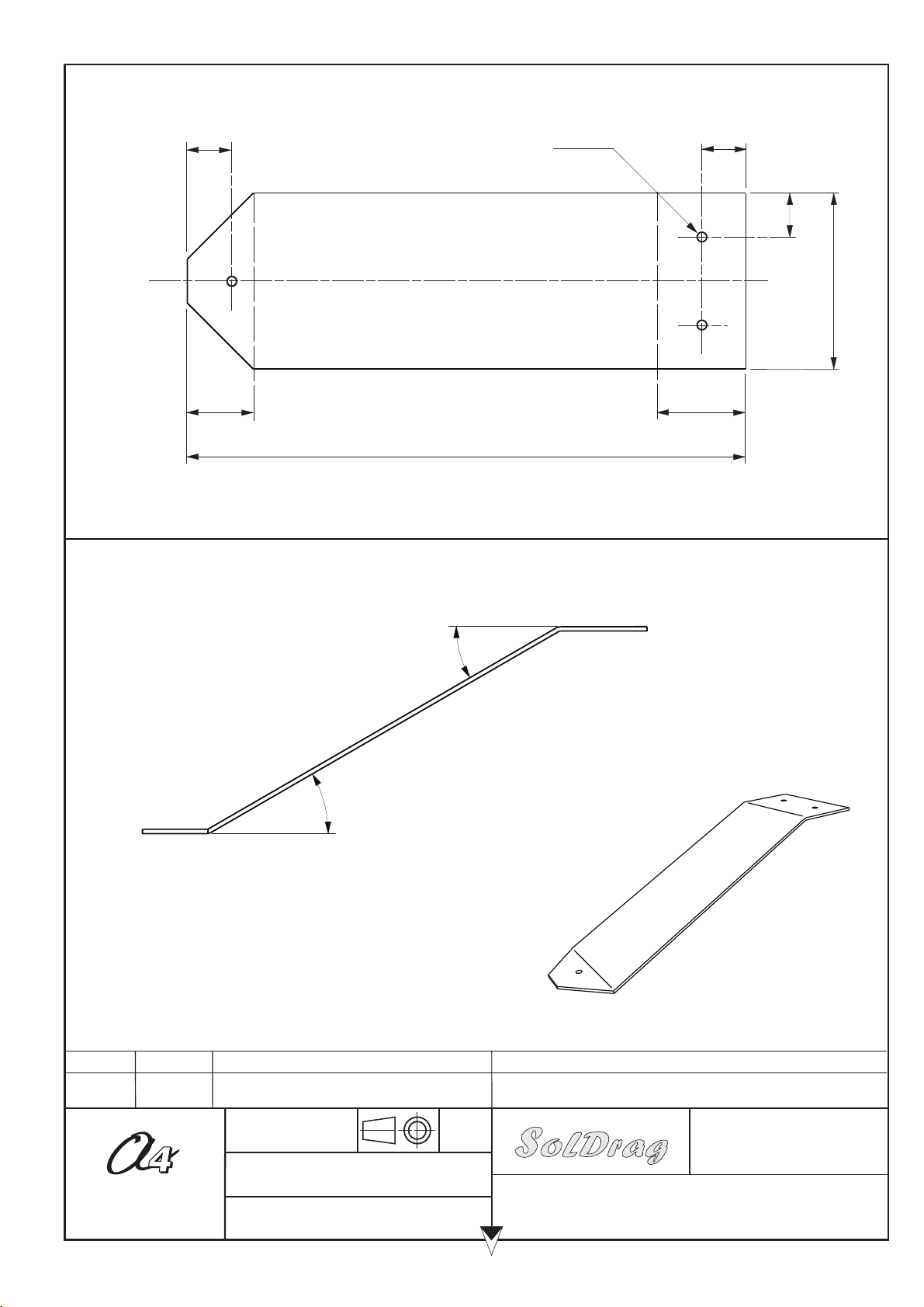
- Chassis: made of expanded PVC 3 x 40 x 127 mm (supplied in the kit): angles cutting + screws pointing
- Photovoltaic cell support: made of 6 x 20 x 40 mm expanded PVC: cutting + drilling.
- Cover: made of HIPS (High Impact Polystyrene) 1 x 40 x 127 mm (correct dimensions provided in the kit): angles cutting
+ drilling.
- Cell support aluminium wire to be shaped
- Angles to be cut again + small diameters drilling + hot bending on thermo-bender with resistant wire or cold bending.
- PropulsO gear motor: provided in separate parts to be assembled.
- Ø 3 steel axles: to be cut again with ends chamfered.
- Wiring: wires to be soldered for to connect photovoltaic cell, motor and switch.
All parts and materials are available in full. The 560-757 reference kit contains the plastic parts ready to be assembled as
well as all other parts and components (see page 16).
A cell converts lighting energy into electric energy. There are several technologies for photovoltaic cells, with different
properties and efficiencies:
The photovoltaic cell of the SolDrag vehicle is amorphous; it is the best in terms of cost, but it is only efficient in a limited
wave length range, near infrared.