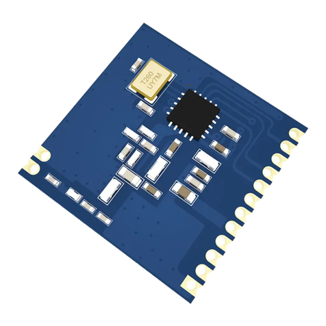
A7 Engineering EmbeddedBlue 500 User manual

EmbeddedBlue™500
User Manual

2 User Manual
Copyright ©2003 A7 Engineering, Inc.
Part Number 0000033 – Revision A
Last revised on December 4, 2003 – Printed in the United States of America
A7 Engineering, Inc.
12860 C Danielson Court
Poway, CA 92064
Copyright ©2003 A7 Engineering, Inc. All rights reserved. EmbeddedBlue is a trademark of
A7 Engineering, Inc. PBASIC is a trademark and BASIC Stamp is a registered trademark of
Parallax, Inc. Bluetooth and the Bluetooth logo are registered trademarks of the Bluetooth
SIG. Windows is a registered trademark of Microsoft Corporation. Other brand and product
names are trademarks or registered trademarks of their respective holders.
The information contained in this document is subject to change without notice. A7
Engineering, Inc. and its staff make no warranty of any kind for the correctness,
completeness, interpretation or use of the information contained herein. It is the user’s
responsibility to comply with all applicable copyright laws.

EmbeddedBlue 500 3
Copyright ©2003 A7 Engineering, Inc.
Table of Contents
Introduction .......................................................................................................................................... 7
Manual Conventions .......................................................................................................................... 7
eb500 Basics ........................................................................................................................................ 8
Command Mode ................................................................................................................................ 8
Data Mode ......................................................................................................................................... 8
I/O Lines............................................................................................................................................. 9
Resetting the eb500 to the Factory Default Settings......................................................................... 9
Switching between Data Mode and Command Mode ....................................................................... 9
BASIC Stamp Application Debugging ............................................................................................. 13
Hardware Connections ...................................................................................................................... 14
Board Of Education ......................................................................................................................... 15
Basic Stamp Activity Board.............................................................................................................. 16
BS2P40 Demo Board ...................................................................................................................... 17
Javelin Stamp Demo Board............................................................................................................. 18
SumoBoard...................................................................................................................................... 19
Super Carrier Board......................................................................................................................... 20
Establishing a Connection ................................................................................................................ 21
Connecting two eb500 Modules ...................................................................................................... 21
Connecting a PC with an eb600 to a Board of Education ............................................................... 25
Connecting a PC with a DBT-120 to a BOE.................................................................................... 28
Connecting a BOE to a PC with a DBT-120 .................................................................................... 32
Connecting an iPAQ h1940 to a Board of Education ...................................................................... 35
Connecting a Board of Education to an iPAQ h1940 ...................................................................... 37
Communications ................................................................................................................................ 40
Communicating between Two eb500 Modules................................................................................ 40
Communicating between a PC with an eb600 and a BOE.............................................................. 46
Communicating between a PC with a DBT-120 and a BOE ........................................................... 51
Communicating between an iPAQ h1940 an a BOE....................................................................... 57
eb500 Commands .............................................................................................................................. 63
Command Basics............................................................................................................................. 63
BASIC Stamp Application eb500 Command Error Handling........................................................... 64
Connect............................................................................................................................................ 65
Disconnect ....................................................................................................................................... 66
Get Address..................................................................................................................................... 67
Get Connectable Mode.................................................................................................................... 68
Get Discoverable Mode ................................................................................................................... 69
Get Escape Character ..................................................................................................................... 70
Get Flow Control.............................................................................................................................. 71
Get Link Timeout ............................................................................................................................. 72
Help.................................................................................................................................................. 73
List ................................................................................................................................................... 74
Return to Data Mode ....................................................................................................................... 75
Set Baud Rate ................................................................................................................................. 76
Set Connectable Mode .................................................................................................................... 77
Set Discoverable Mode.................................................................................................................... 78
4 User Manual
Copyright ©2003 A7 Engineering, Inc.
Set Escape Character...................................................................................................................... 79
Set Flow Control .............................................................................................................................. 80
Set Link Timeout.............................................................................................................................. 81
Switch to Command Mode............................................................................................................... 82
Version............................................................................................................................................. 83
eb500 Error Codes ............................................................................................................................. 84
Technical Specifications ................................................................................................................... 85
Operating Parameters ..................................................................................................................... 85
Dimensions ...................................................................................................................................... 86
Pinout Diagram ................................................................................................................................ 87
Frequently Asked Questions ............................................................................................................ 88
Contact Information ........................................................................................................................... 90

EmbeddedBlue 500 5
Copyright ©2003 A7 Engineering, Inc.
Table of Figures
Figure 1: eb500 Module........................................................................................................ 14
Figure 2: Board of Education Board ..................................................................................... 15
Figure 3: Basic Stamp Activity Board ................................................................................... 16
Figure 4: BS2P40 Demo Board ............................................................................................ 17
Figure 5: Javelin Stamp Demo Board................................................................................... 18
Figure 6: SumoBoard............................................................................................................ 19
Figure 7: Super Carrier Board .............................................................................................. 20
Figure 8: eb500 Bluetooth Address Output .......................................................................... 23
Figure 9: iPAQ Bluetooth Authorization Request Dialog ...................................................... 39
Figure 10: HyperTerminal Input and Debug Output.............................................................. 47
Figure 11: HyperTerminal Output - Hello World ................................................................... 50
Figure 12: Hello World Pocket PC Application ..................................................................... 58
Figure 13: iPAQ Bluetooth Brower Dialog ............................................................................ 59
Figure 14: RXEB500 Pocket PC Application ........................................................................ 61
Figure 15: eb500 Dimensions............................................................................................... 86
Figure 16: eb500 Pinout Diagram......................................................................................... 87

6 User Manual
Copyright ©2003 A7 Engineering, Inc.
Table of Tables
Table 1: eb500 Error Codes ................................................................................................. 84
Table 2: eb500 Operating Parameters ................................................................................. 85
Table 3: eb500 Dimensions .................................................................................................. 86
Table 4: eb500 Pinout Description........................................................................................ 87

EmbeddedBlue 500 7
Copyright ©2003 A7 Engineering, Inc.
Introduction
Congratulations on your purchase of the EmbeddedBlue 500 (eb500) module. The eb500
module provides Bluetooth®connectivity for 8/16 bit microcontroller applications without
having to know the details of Bluetooth technology. Hobbyists, developers, and OEMs can
take advantage of advanced wireless connectivity with this easy to use module.
The eb500 module provides a point to point connection much like a standard serial cable.
Connections are made dynamically and can be established between two eb500 modules or
an eb500 module and a standard Bluetooth v1.1 device. Devices can be dynamically
discovered and connected in an ad-hoc manner.
Manual Conventions
Below is a list of typographical conventions used in this manual:
Text in this font
•Is used to show data that is sent to the eb500.
•Inside a gray box is used to show data that is sent from
the eb500.
Text in this font
•Is used to show source code.
In the eb500 Commands section of this manual
•Required parameters and placeholders appear in standard lowercase type.
•Placeholders appear in italics. For example, if address shows up in a syntax line,
the actual address of the device must be entered.
•Required parameter options are separated by a vertical bar |.
•Optional parameters are enclosed in brackets [ ].

8 User Manual
Copyright ©2003 A7 Engineering, Inc.
eb500 Basics
The eb500 supports two main operating modes: command mode and data mode. Upon
power up the eb500 enters command mode and is ready to accept serial commands. The
factory default communication parameters are 9600 Baud, 8 Data Bits, 1 Stop Bit, No Parity,
and No Flow Control. The eb500 supports commands to modify the baud rate and flow
control settings.
Command Mode
In this mode there are a number of commands that can be sent to change the baud rate,
locate other devices that are in range, check the firmware version, etc. All commands are
sent using visible ASCII characters (123 is 3 bytes “123”). Upon the successful transmission
of a command, the ACK string will be returned. If there is a problem in the syntax of the
transmission a NAK string is returned. After either the ACK or NAK, a carriage-return <CR>
character is returned. When a prompt (<CR> followed by a ‘>’) is returned, it means that the
eb500 radio is in the idle state and is waiting for another command. White spaces do matter
and are used to separate argument parameters of the command and a carriage-return
<CR> (ASCII 13) is used to mark the end of the command.
Data Mode
Once the eb500 radio is connected to another Bluetooth device, the eb500 automatically
switches into data mode. All data transmitted while in this mode will be sent to the remote
device and, therefore, NO further commands can be sent until the eb500 radio is
disconnected or switched back to command mode by use of the mode control I/O line or the
Switch to Command Mode command.
The connection status line of the eb500 module can be monitored to determine if there is an
active connection. Additionally, whenever a connection is present, the Connection Status
LED (Figure 1) on the eb500 module will be on.

EmbeddedBlue 500 9
Copyright ©2003 A7 Engineering, Inc.
I/O Lines
The eb500 module features a 20 pin header for connecting to the Parallax AppMod header.
A full device pinout is available in the Technical Specifications section of this manual. There
are several pins that are important when performing the exercises in the Establishing a
Connection and Communications sections of this manual.
Pin 3 of the eb500 module, which aligns with the pin designated “P0” of the AppMod
header, is the UART data output pin.
Pin 4 of the eb500 module, which aligns with the pin designated “P1” of the AppMod
header, is the UART data input pin.
Pin 8 of the eb500 module, which aligns with the pin designated “P5” of the AppMod
header, is the Connection Status pin. A BASIC Stamp application can interrogate this
pin to determine the connection status of the eb500 radio.
Pin 9 of the eb500 module, which aligns with the pin designated “P6” of the AppMod
header, is the Mode Control pin. A BASIC Stamp application can drive this pin high
to enter Data Mode or low to enter Command Mode.
Resetting the eb500 to the Factory Default Settings
The eb500 module can be reset to the factory default settings by shorting Pin 8 and Pin 9
and then applying power to the eb500 module.
Switching between Data Mode and Command Mode
When a Connection command is issued, the eb500 attempts to establish a connection to the
device with the address specified in the command. Once a connection is established, the
eb500 switches into data mode. At this point all data sent to the eb500 is transmitted to the
remote Bluetooth device over the wireless link. It is possible to switch from data mode to
command mode, issue commands, and then return to data mode, while maintaining a
connection. The eb500 allows you to switch between data mode and command mode by
issuing the Switch to Command Mode and Return to Data Mode serial commands or by
driving the mode control I/O line (Pin 9) of the eb500 module.
The following BASIC Stamp application uses the Switch to Command Mode and Return to
Data Mode serial commands to switch between data mode and command mode. This
application is available in electronic form on the accompanying CD in the Samples folder in
the file CmdModeSoft.bs2.
'{$STAMP BS2}
szData VAR BYTE(20)
'Wait for the eb500 radio to be ready
PAUSE 1000
'Connect to the remote device

10 User Manual
Copyright ©2003 A7 Engineering, Inc.
SEROUT 1,84,["con 00:0C:84:00:07:D8",CR]
SERIN 0,84,[WAIT("ACK",CR)]
WaitForConnection:
IF in5 = 0 THEN WaitForConnection
DEBUG "Connected",CR
SEROUT 1,84,["This text is sent in data mode",CR]
'Switch to Command Mode
PAUSE 2000
SEROUT 1,84,["+++"]
SERIN 0,84,[WAIT(CR,">")]
DEBUG "In Command Mode",CR
'Get the eb500 Bluetooth Address
SEROUT 1,84,["get addr",CR]
SERIN 0,84,[WAIT("ACK",CR)]
'Read the local address from the get command
SERIN 0,84,[STR szData\17]
SERIN 0,84,[WAIT(CR,">")]
szData(17) = 0
DEBUG STR szData\17,CR
'Return to Data Mode
SEROUT 1,84,["ret",CR]
SERIN 0,84,[WAIT("ACK",CR)]
DEBUG "In Data Mode",CR
SEROUT 1,84,["My Bluetooth address is ",STR szData,CR]
'Switch to Command Mode
PAUSE 2000

EmbeddedBlue 500 11
Copyright ©2003 A7 Engineering, Inc.
SEROUT 1,84,["+++"]
SERIN 0,84,[WAIT(CR,">")]
DEBUG "In Command Mode",CR
'Disconnect from remote device
SEROUT 1,84,["dis",CR]
SERIN 0,84,[WAIT(CR,">")]
DEBUG "Disconnected",CR
The following BASIC Stamp application uses the mode control I/O line of the eb500 module
to switch between data mode and command mode. Switching between data mode and
command mode via the mode control I/O line is preferred, as it is faster than the serial
method. This application is available in electronic form on the accompanying CD in the
Samples folder in the file CmdModeHard.bs2.
'{$STAMP BS2}
szData VAR BYTE(20)
'Wait for the eb500 radio to be ready
PAUSE 1000
'Connect to the remote device
SEROUT 1,84,["con 00:0C:84:00:07:D8",CR]
SERIN 0,84,[WAIT("ACK",CR)]
WaitForConnection:
IF in5 = 0 THEN WaitForConnection
DEBUG "Connected",CR
SEROUT 1,84,["This text is sent in data mode",CR]
'I/O Line 6 allows us to switch to Command Mode
OUTPUT 6
'Switch to Command Mode
LOW 6
SERIN 0,84,[WAIT(CR,">")]
DEBUG "In Command Mode",CR

12 User Manual
Copyright ©2003 A7 Engineering, Inc.
'Get the eb500 Bluetooth Address
SEROUT 1,84,["get addr",CR]
SERIN 0,84,[WAIT("ACK",CR)]
'Read the local address from the get command
SERIN 0,84,[STR szData\17]
SERIN 0,84,[WAIT(CR,">")]
szData(17) = 0
DEBUG STR szData\17,CR
'Return to Data Mode
HIGH 6
PAUSE 50
DEBUG "In Data Mode",CR
SEROUT 1,84,["My Bluetooth address is ",STR szData,CR]
'Switch to Command Mode
LOW 6
SERIN 0,84,[WAIT(CR,">")]
DEBUG "In Command Mode",CR
'Disconnect from remote device
SEROUT 1,84,["dis",CR]
SERIN 0,84,[WAIT(CR,">")]
DEBUG "Disconnected",CR

EmbeddedBlue 500 13
Copyright ©2003 A7 Engineering, Inc.
BASIC Stamp Application Debugging
When debugging your BASIC Stamp application that uses an eb500 it is important that the
BASIC Stamp application and the eb500 are in sync. When the BASIC Stamp Editor begins
the downloading process the BASIC Stamp is reset; however, this reset does not reset the
eb500. This can cause an existing application on the BASIC Stamp to begin executing,
which can lead to a situation where the new application and the eb500 are not in sync. It is
possible that the eb500 could be in Data Mode or in an unpredictable command mode state,
due to the execution of the existing BASIC Stamp application. Therefore, during the
application debugging process, it is recommended that the following code be inserted at the
beginning of your BASIC Stamp application, before you read or set any I/O points or issue
any commands to the eb500.
‘*************************************************************
IF in5 = 0 THEN ClearCmd
DEBUG “eb500 Connected (in Data Mode)”,CR
‘Switch to Command Mode
LOW 6
SERIN 0,84,[WAIT(CR,”>”)]
‘Disconnect from the remote device
SEROUT 1,84,[“dis”,CR]
SERIN 0,84,[WAIT(CR,”>”)]
GOTO Start
ClearCmd:
DEBUG “eb500 in Command Mode”,CR
‘Issue a carriage-return to clear any commands
SEROUT 1,84,[CR]
SERIN 0,84,[WAIT(“>”)]
‘*************************************************************

14 User Manual
Copyright ©2003 A7 Engineering, Inc.
Hardware Connections
The eb500 module is designed to interface with a 5V CMOS signal environment. It supports
a power supply of 5 – 12V and can be connected directly to boards supporting the Parallax
AppMod header. When inserting the eb500 module to any of the supported Parallax boards,
it is important that Pin 1 of the eb500 module, marked with a white dot and a square (Figure
1), is inserted into the VSS pin of the AppMod header on the Parallax boards. A full device
pinout is available in the Technical Specifications section of this manual.
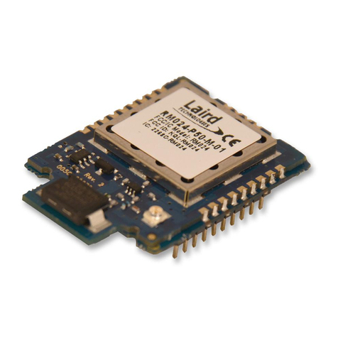
Figure 1: eb500 Module
Pin 1
Connection
Status LED

EmbeddedBlue 500 15
Copyright ©2003 A7 Engineering, Inc.
Board Of Education
The Board Of Education (BOE) contains an AppMod header and supports a direct
connection with the eb500 module. On the Board of Education, the AppMod header
is labeled X1 (Figure 2). When inserting the eb500 module into the Board of
Education AppMod header, assure that you insert Pin 1 of the eb500 module,
marked with a white dot and a square, into the VSS pin of the AppMod header.
www.stampsinclass.com
Reset
STAMPS
CLASS
in
Board of Education
Pwr
9 Vdc
Battery
6-9VDC
Sout
Sin
ATN
Vss
P0
P1
P2
P3
P4
P5
P6
P7
P11
P9
P8
Vin
P10
P15
P14
P13
P12
Vdd
Rst
Vss
Black
Red
X4 X5
15 14 13 12
1
X1
Vss
P1
P3
P5
P7
P9
P11
P13
P15
Vin
Vss
P0
P2
P4
P6
P8
P10
P12
P14
Vdd
U1
TM
0 1 2
© 2000-2003
Vdd
P15
P14
P13
P12
P11
P10
P9
P8
P7
P6
P5
P4
P3
P2
P1
P0
X2
X3
Vdd VssVin
Figure 2: Board of Education Board
AppMod
Header
VSS Pins

16 User Manual
Copyright ©2003 A7 Engineering, Inc.
Basic Stamp Activity Board
The Basic Stamp Activity Board contains an AppMod header and supports a direct
connection with the eb500 module when using a BS2 processor. On the Basic Stamp
Activity Board, the AppMod header is labeled X7 (Figure 3). When inserting the
eb500 module into the Basic Stamp Activity Board AppMod header, assure that you
insert Pin 1 of the eb500 module, marked with a white dot and a square, into the
VSS pin (Pin 1) of the AppMod header.
Pwr
Reset
Stamp Activity Board
(c)1998
6-12VAC
9-24VDC
Need Tech Support?
email stamptech@parallaxinc.com
www.parallaxinc.com
X7
20
19
X1 X4
X5
P4/11 P5/10 P6/9 P7/8
TM
P5/7
C5
P3/12
X3
P4/11
X2
A B
Aout
+
_
P0=mPin
P1=zPin
Rev C
1 2
↓
X6
2
1
C6C71
1
1
BS1-IC
BS2-IC
X8
1
2
Figure 3: Basic Stamp Activity Board
AppMod
Header
VSS Pins

EmbeddedBlue 500 17
Copyright ©2003 A7 Engineering, Inc.
BS2P40 Demo Board
The BS2P40 Demo Board contains an AppMod header and supports a direct
connection with the eb500 module. On the BS2P40 Demo Board, the AppMod
header is labeled X1 (Figure 4). When inserting the eb500 module into the BS2P40
Demo Board AppMod header, assure that you insert Pin 1 of the eb500 module,
marked with a white dot and a square, into the VSS pin of the AppMod header.
P40DemoBoard
Power
©2002
X6
JU2
Reset
6-9 VDC
1 2 3 4 5 6 7 8 9 101112131415161718192021222324252627282930
1 2 3 4 5 6 7 8 9 101112131415161718192021222324252627282930
a
b
c
d
e
f
g
h
I
j
k
l
a
b
c
d
e
f
g
h
I
j
k
l
A15
A14
A13
A12
A11
A10
A9
A8
A7
A6
A5
A4
A3
A2
A1
A0
X5
P15
P14
P13
P12
P11
P10
P9
P8
P7
P6
P5
P4
P3
P2
P1
P0
X4
JU1
Vdd
P14
P12
P10
P8
P6
P4
P2
P0
Vin
Vin
P15
P13
P11
P9
P7
P5
P3
P1
Vss
X1
1
BS2p24
BS2p40
1
1
U1
X2
VddVss
Vin
X3
Vdd
VssVin
Figure 4: BS2P40 Demo Board
AppMod
Header
VSS Pins

18 User Manual
Copyright ©2003 A7 Engineering, Inc.
Javelin Stamp Demo Board
The Javelin Stamp Demo Board contains an AppMod header and supports a direct
connection with the eb500 module. On the Javelin Stamp Demo Board, the AppMod
header is labeled X1 (Figure 5). When inserting the eb500 module into the Javelin
Stamp Demo Board AppMod header, assure that you insert Pin 1 of the eb500
module, marked with a white dot and a square, into the VSS pin of the AppMod
header.
Figure 5: Javelin Stamp Demo Board
AppMod
Header
VSS Pins

EmbeddedBlue 500 19
Copyright ©2003 A7 Engineering, Inc.
SumoBoard
The SumoBoard contains an AppMod header and supports a direct connection with
the eb500 module. On the SumoBoard, the AppMod header is labeled X10 (Figure
6). When inserting the eb500 module into the SumoBoard AppMod header, assure
that you insert Pin 1 of the eb500 module, marked with a white dot and a square, into
the VSS pin of the AppMod header.
Figure 6: SumoBoard
AppMod
Header
VSS Pins

20 User Manual
Copyright ©2003 A7 Engineering, Inc.
Super Carrier Board
The Super Carrier Board contains an AppMod header and supports a direct
connection with the eb500 module. On the Super Carrier Board, the AppMod header
is labeled X1 (Figure 7). When inserting the eb500 module into the Super Carrier
Board AppMod header, assure that you insert Pin 1 of the eb500 module, marked
with a white dot and a square, into the VSS pin of the AppMod header.
Reset
Pwr
Need Tech Support?
Send email to:
stamptech@parallaxinc.com
Basic Stamp Super Carrier
www.parallaxinc.com (916) 624-8333 ©1999
J3
TM
C2
+
Rev A
C3
J1
C4
P15
P14
P13
P12
P11
P10
P9
P8
P7
P6
P5
P4
P3
P2
P1
P0
Vdd
Vdd
Vss
Vss
Vss
C1
Vin
Vss
PCO
PCI
Vdd
Rst
P0
P1
P2
P3
P4
P5
P6
P7
Vin
J2
Vss
Rocklin, CA - USA
Figure 7: Super Carrier Board
AppMod
Header
VSS Pins
This manual suits for next models
1
Table of contents