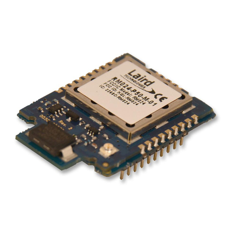
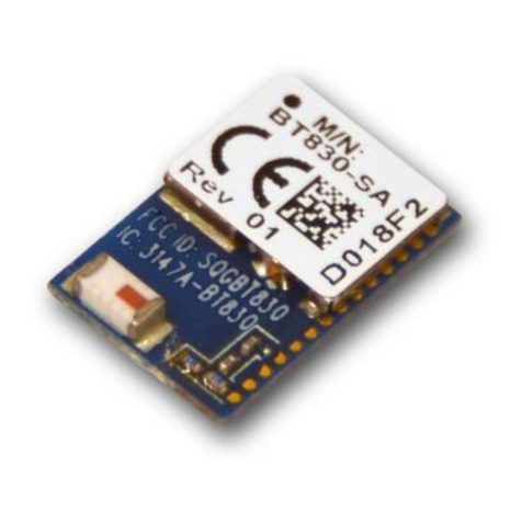
Navien BCM-40RW User manual

ŘŪųŦŭŦŴŴġ
ńŰŮŮŶůŪŤŢŵŪŰůġ
ŎŰťŶŭŦ
.PEFM
#$.38
*OTUBMMBUJPO0QFSBUJPO.BOVBM

$PQZSJHIUJOGPSNBUJPO
˖
,%/BWJFO*OD"MMSJHIUTSFTFSWFE
˖
8J'JmUIF8J'J$&35*'*&%MPHP
BOEUIF8J'JMPHPBSFSFHJTUFSFE
USBEFNBSLTPGUIF8J'J"MMJBODF
˖
5SBEFNBSLTBOEUSBEFOBNFTVTFE
JOUIJTNBOVBMBSFUIFQSPQFSUZPG
UIFJSSFTQFDUJWFPXOFST
*GZPVSEFWJDFSFRVJSFTTFSWJDFZPV
IBWFTFWFSBMPQUJPOTGPSHFUUJOH
TFSWJDFDPOUBDU5FDIOJDBM4VQQPSU
BUPSPOUIFXFCTJUF
IUUQTOBWJFOVLDPN
'PSXBSSBOUZTFSWJDFBMXBZTDPOUBDU
5FDIOJDBM4VQQPSUGJSTU
5&-
"EE#VJMEJOH(SPVOE'MPPS
(VJMGPSE#VTJOFTT1BSL
(VJMEGPSE(69)

3
DANGER
• Do not supply 230 VAC to this device.
_
Doing so may result in fire, severe
personal injury, or death.
Safety information
Read and follow all safety instructions
in this manual to avoid unsafe operating
conditions, property damage, personal
injury, or death.
Safety messages used in this
manual
DANGER
Indicates an imminently hazardous
situation which, if not avoided, could
result in severe injury or death.
WARNING
Indicates a potentially hazardous
situation which, if not avoided, could
result in injury or death.
CAUTION
Indicates a potentially hazardous
situation that, if not avoided, could
result in property damage.

4
• Avoid interference with other
electronic devices.
_
The device emits radio frequency
(RF) signals that may interfere with
unshielded or improperly shielded
electronic equipment, such as
pacemakers, hearing aids, medical
devices, and other electronic
devices. Consult the manufacturers
of your electronic devices to solve
any interference problems you
experience.
• When mounting the device on a wall,
make sure that the wall is strong
enough to support the device.
_
The device could fall if the wall is
not strong enough and this may
damage the device or cause injury.
WARNING
• This device is designed for indoor
use. Please install and use this
device indoors.
• Do not disassemble or attempt to
repair the device.
_
You may damage the device.
_
Any attempt to disassemble or
repair the device voids Navien’s
Limited Warranty. Navien is not
responsible for damage or injuries
caused by voiding the Navien’s
Limited Warranty.
• Do not store flammable materials
near the device.
_
This may cause a fire or damage
the device.
_
Keep all flammable products far
away from the device and store
them in approved containers.
Keep the containers closed tightly
and out of the reach of children
and pets.
5
• Do not use loose or damaged cables.
_
This may result in a poor
connection or cause the device to
malfunction.
• This device has been approved for
use in the UK and EU only.
_
Using the device in any other
country will void the manufacturer’s
warranty.
CAUTION
• Use suitable tools and appropriate
force to install the device.
_
Using unsuitable tools or excessive
force during installation may
damage the device.
• Do not expose the device to direct
sunlight or high temperatures for an
extended period of time.
_
Prolonged exposure to sunlight or
extreme temperature can cause
permanent damage to the device’s
internal components.
• Avoid water and wet areas.
_
This may damage the device’s
internal components. Always keep
the device dry.
• Do not clean the device with water
or a damp cloth.
_
You may damage the device.
• Do not install the device in very hot
or very cold areas. The operating
temperature of the device is 0℃–40℃.

6
Contents
Overview ..............................7
Supplied items ...................................9
Device layout ....................................10
Installing the wireless
communication module........13
Connecting the KIW
communication cable ......................13
Attaching the wall mounting plate .. 16
Pairing with the RF receivers 17
Connecting to a Wi-Fi
network (For App use) .......... 19
Resetting the connection
data ....................................21
Resetting Wi-Fi connection data ......21
Resetting RF connection data ..........21
Resetting the Wi-Fi and RF
connection data simultaneously .....21
Troubleshooting ...................22
Recycling and disposal .........24
Recycling the package .....................24
WEEE: Recycling or disposing of
the device and its parts ....................24
Warranty..............................25
Specifications ......................26

7
Navien Smart Plus uses 2-way communication on an 868 MHz radio frequency (RF)
band to control the heating system. The wireless communication module (BCM-40RW)
operates as the control centre of the system, and the Navien boilers (LCB700 or NCB-CE)
support 2-wire communication (KIW) technology. It is possible to control it using a
2-wire connection from the BCM-40RW terminals.
Navien Smart Plus consists of the wireless thermostat (NRC-10R) and wireless
communication module (BCM-40RW). The devices are already paired (completed
RF pairing procedure). Therefore, when installing them, no additional initial pairing
procedure is needed to use the devices.
Navien Smart Plus can be installed in combi/system and regular boilers. With an
additional wireless thermostat (NRC-10R) and an additional wireless wiring centre (VCU-
10R), multizone control can be implemented in a combi boiler environment via the S/S+
Plan and in a system/regular boiler environment with the S/S+/Y/W Plan.
Charge for App service is subject to be imposed after prior notice in accordance with the
policy of the manufacturer.
Applicable devices with
BCM-40RW
Specifications
Model name Power input Radio frequency
(RF)
Thermostat NRC-10R AA batteries x 2 868 MHz
Wiring centre VCU-10R 230 VAC, Hz 868 MHz
Main controller (boiler) LCB700 or NCB-CE 230 VAC -
Overview

8
VCU-10R
BCM-40RW
Navien boiler
KIW
Comm
Zone1 Zone2 Zone3
Or
NCB-CE
LCB700
NRC-10R
• This device specifications or contents of this manual may be changed without
prior notice due to upgrade of device functions.
• The device functions can be limited by the operating environment.

9
Supplied items
Open the packaging and ensure that the following items are provided.
Wireless communication
module Screws and anchors Wall mounting plate
Extension cable Installation & Operation
manual

10
Device layout
The following table provides the brief information on each part of the wireless
communication module.
5
4
2
1
3
No Name Description
1Wi-Fi
button Press and hold to enter or exit Wi-Fi AP mode.
2RF
button Press and hold to enter or exit RF pairing mode.
3Reset
button
Insert the tip of a sharp object to reset the RF or Wi-Fi connection data.
For more information about resetting the connection data, refer to
"Resetting the connection data" on page 21.

11
No Name Description
4
Wi-Fi
LED
status
Indicates the Wi-Fi operation (AP mode) status.
LED
Colour Status Description
Red
On
• The wireless communication module is
booting for Wi-Fi communication.
• There is no Wi-Fi network connected to
the wireless communication module.
• The Wi-Fi AP mode is turned off.
Blinking
(Slow: 0.5 sec) The device is in Wi-Fi AP mode.
Blinking
(Quick: 0.2 sec) The device is entering AP mode.
Green Blinking
Wi-Fi AP (router) access trial is being performed.
Blue
On The wireless communication module is
properly connected to the server.
Blinking
• When the wireless communication
module is connecting to the server, the
Wi-Fi LED status will blink blue slowly.
• When the wireless communication
module is transmitting and receiving
server data, the Wi-Fi LED status will
blink slowly or quickly depending on
the size of the server data.

12
No Name Description
5RF LED
status
Indicates the RF operation status between the wireless communication
module and paired RF devices.
LED
Colour Status Description
Red
On
• The wireless communication module is
booting for RF communication.
• There are no devices paired with the
wireless communication module.
• The RF pairing mode is turned off.
Blinking
(Slow: 0.5 sec)
The wireless communication module is in
RF pairing mode.
Blinking
(Quick: 0.2 sec)
The wireless communication module is
entering RF pairing mode.
Green Blinking
There is a poor connection between the
wireless communication module and paired
devices.
Blue
On The wireless communication module is
properly paired with devices.
Blinking
When the wireless communication module
is transmitting and receiving RF data, the
RF LED status will blink slowly or quickly
depending on the size of the RF data.

13
Connecting the KIW
communication cable
The KIW communication cable from
the boiler must be connected to the
wireless communication module.
Do not supply 230 VAC to the
wireless communication module.
Doing so may result in fire, severe
personal injury, or death.
Installing the wireless communication module
Connect the KIW communication
cable from the boiler to the wireless
communication module and install it
on a wall near the boiler as the boiler
provides power for the communication
module.
Also, for the best RF system performance,
install the wireless communication
module in an open area so that it can
pair with the wiring centre and wireless
thermostats.
• Do not install the wireless
communication module near
heat sources, such as radiators,
chimney walls, televisions, and
direct sunlight. Doing so may
damage the device.
• Install the wireless
communication module at least
30 cm from any metal objects,
including wall boxes, and at least
1 m from any other electrical
equipment, such as radios,
televisions, and PCs. Metal
objects and electrical equipment
may affect the RF communication
between RF devices.

14
1
Connect one end of the extension cable to the port on the front panel of the boiler
and the end of the extension cable to one end of the KIW communication cable from
the wireless communication module.
<For NCB-CE boilers>
<For LCB700 boilers>
Set the DIP switches for NCB-CE and LCB700 boilers as follows.
• NCB-CE Panel DIP SW: 4-OFF, 5-OFF
• LCB700 Boiler DIP SW2: 6-OFF, 7-ON, 8-OFF

15
3
Connect the KIW communication
cable to the wireless communication
module’s power terminal block on
the wall mounting plate.
2
Pass one end of the KIW
communication cable from the
boiler through the hole in the wall
mounting plate.

16
2
Hang the wireless communication
module on the wall mounting plate
by aligning the hooks.
You will hear a "click" sound when
the wireless communication module
is securely hung.
Attaching the wall mounting
plate
1
Check the direction of the wall
mounting plate and affix it to the
wall using four screws.

17
• For the best RF system
performance, install the wireless
communication module in an
open area so that it can pair with
the wiring centre and wireless
thermostats.
• Only one wiring centre can
be paired with the wireless
communication module.
When pairing the wireless
communication module with the RF
receivers, such as the wiring centre or
wireless thermostat, the devices should
be in pairing mode. Refer to the Wireless
thermostat or Wiring centre Installation
& Operation manual for information on
entering pairing mode.
Pairing with the RF receivers

18
4
Press and hold the RF button to exit
pairing mode, and then check if
the RF devices are paired with the
wireless communication module by
monitoring the RF devices.
• Pairing mode automatically ends
approximately 5 minutes after
the wireless communication
module enters pairing mode.
• If the wireless communication
module does not exit pairing
mode, it cannot communicate
with the paired RF devices.
• Check if the RF signal antenna
icon on the wireless thermostat
LCD screen appears during
pairing mode.
1
Turn on the power to the wireless
communication module.
2
Press and hold the RF button to enter
pairing mode. If the RF LED status
blinks red slowly, pairing mode is
turned on.
To cancel or exit pairing mode,
press and hold the RF button.
3
On the RF devices being paired
with the wireless communication
module, enter pairing mode. The
wireless communication module
will automatically pair with the RF
devices.

19
Connecting to a Wi-Fi network (For App use)
• To cancel or end AP mode, press
and hold the Wi-Fi button.
• The Product registration
screen also appears during app
member registration.
The wireless communication module
allows your smartphone to control
the wireless thermostats. Before
using the wireless thermostats via
the Navien Smart Plus app, connect
your smartphone with the wireless
communication module.
To connect your smartphone
with the wireless communication
module, download and install the
Navien Smart Plus app on your
smartphone. For more detailed
information on using the app,
refer to the Navien Smart Plus app
User Manual.
1
Turn on the power to the wireless
communication module.
2
On your smartphone, log into the
Navien Smart Plus app.
3
When the Product registration screen
appears, press and hold the Wi-Fi
button to enter AP mode. If the Wi-Fi
LED status blinks red slowly, the AP
mode is turned on.

20
5
From the Wi-Fi network list, select
the available Wi-Fi network and enter
the password.
U+ village
Home
Oce 123
Wireless Hub
Router 1
Router 2
If your smartphone has connected
to the Wi-Fi network successfully,
the wireless communication module
will be connected to the selected
Wi-Fi and the Wi-Fi LED status will
turn blue.
4
Tap Navien_Smart+_XXXX in the
Wi-Fi settings to connect, and then
tap Next.
Navien_Smart+_XXXX
Wi-Fi
Navien_Smart+_XXXX
KD wiring centre
KD thermostat
Table of contents