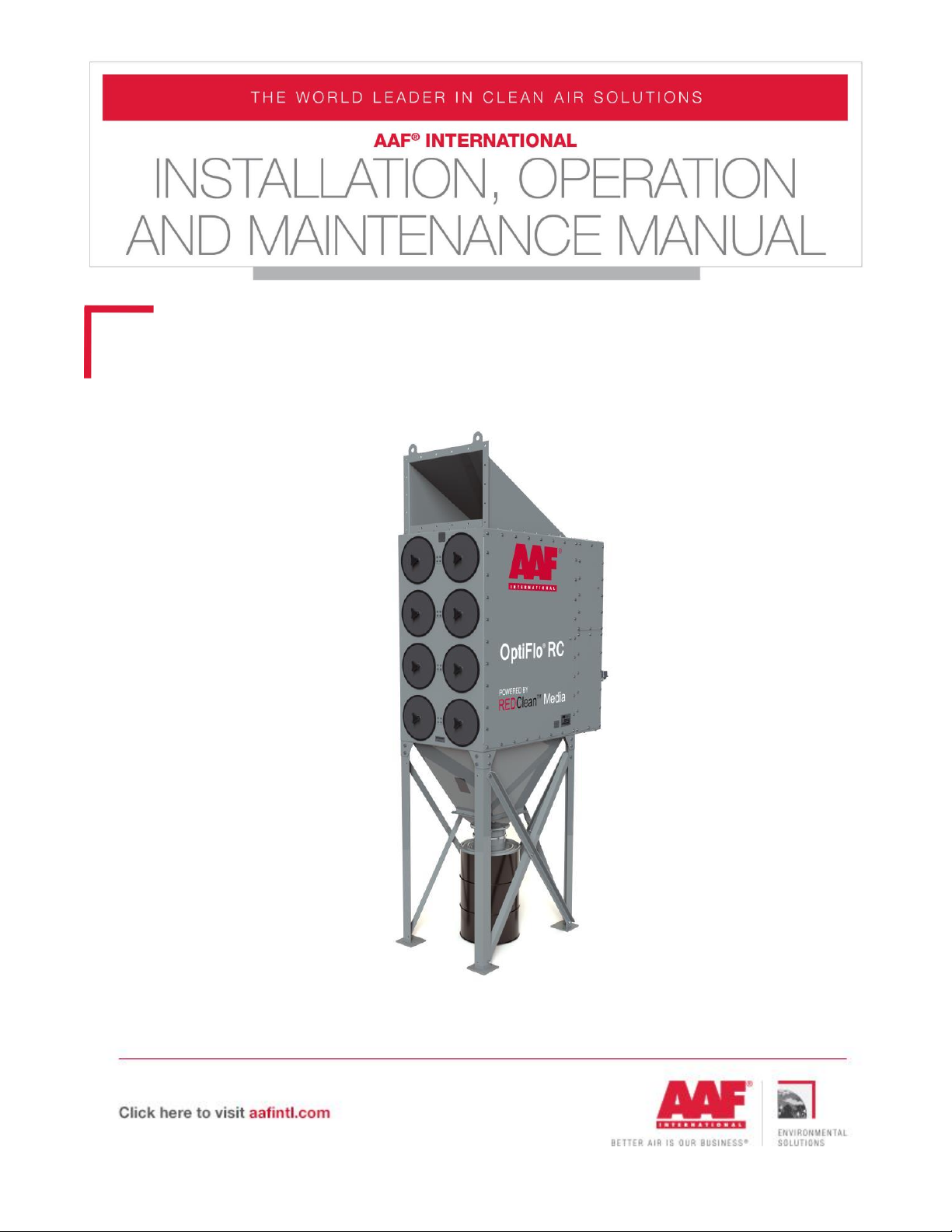
AAF OptiFlo RC Series User manual

GDED-IOM-215-A
OptiFlo®RC

© 2019 American Air Filter Company, Inc. Any use of the text or images
this document contains, without permission of American Air Filter
Company, Inc., is prohibited. OptiFlo, AAF, REDClean, REDFiltration, and
Reliable Efficient Durable are registered trademarks of American Air Filter
Company, Inc. d/b/a AAF International.
GDED-IOM-215-A
TO ORDER SPARE & REPLACEMENT PARTS
Call 1-800-477-1214
Email: [email protected]
Parts Sales
Power & Industrial
AAF International
9920 Corporate Campus Drive
Suite 2200
Louisville, KY 40223-5000
USA
Internet: http://www.AAFParts.com

3
GDED-IOM-215-A
TABLE OF CONTENTS
1INTRODUCTION .............................................................................................................................................. 5
2SAFETY ............................................................................................................................................................... 5
2.1 Safety statement ................................................................................................................... 5
2.2 Safe working practices and staff training......................................................................... 5
2.3 Dust explosions...................................................................................................................... 6
2.4 Electrical hazards................................................................................................................... 7
2.5 Rotating Equipment .............................................................................................................. 7
2.6 Safety Guards ........................................................................................................................ 8
3GENERAL PRODUCT INFORMATION ........................................................................................................ 8
3.1 Description.............................................................................................................................. 8
3.2 Purpose and intended use ................................................................................................... 8
3.3 Normal Operation .................................................................................................................. 8
3.4 Sizes ......................................................................................................................................... 9
3.1 Filter elements ....................................................................................................................... 9
3.2 Weights.................................................................................................................................. 10
4PRODUCT SHIPMENT ...................................................................................................................................11
4.1 How the product ships........................................................................................................ 11
4.2 Items that ship separately ................................................................................................ 11
5PRODUCT RECEIPT AT THE DESIGNATED DELIVERY POINT ........................................................11
5.1Responsibilities of the customer or customer’s agent................................................. 11
5.2 Receiving ............................................................................................................................... 11
5.3 Inspection on arrival ........................................................................................................... 11
5.4 Damaged goods ................................................................................................................... 11
5.5 Missing goods ....................................................................................................................... 12
6UNLOADING AND HANDLING ...................................................................................................................12
6.1 Unloading and lifting into position ................................................................................... 12
7STORAGE AND PROTECTION ....................................................................................................................12
8SITE PREPARATION ......................................................................................................................................13
8.1 Locating equipment ............................................................................................................ 13
8.2 Foundations .......................................................................................................................... 13
8.3 Anchoring .............................................................................................................................. 13
9ASSEMBLY AND INSTALLATION ..............................................................................................................14
9.1 Introduction .......................................................................................................................... 14
9.2 Assembling and installing the structure ......................................................................... 14
9.2.1 Modular assembly................................................................................................................ 14

4
GDED-IOM-215-A
9.2.2 Flanged joints....................................................................................................................... 14
9.2.3 Products shipped as a single assembly. ......................................................................... 14
9.2.4 Products shipped in multiple modular assemblies ....................................................... 15
9.2.5 Installing the access components .................................................................................... 16
9.2.6 Installation of control panel .............................................................................................. 16
9.2.7 Installation of the cartridge filter elements ................................................................... 16
9.2.8 Installation of accessories ................................................................................................. 17
9.2.9 Electrical connections.......................................................................................................... 17
9.2.10 Compressed air connections ............................................................................................. 19
9.2.11 Ductwork Installation ......................................................................................................... 19
10 EXPLOSION VENTS .......................................................................................................................................20
10.1 Installation of the explosion vent .................................................................................... 20
10.2 Assembly ............................................................................................................................... 20
10.3 Explosion Vent Burst Sensor............................................................................................. 21
10.4 Servicing................................................................................................................................ 22
10.5 Safety distance .................................................................................................................... 22
11 START-UP & OPERATION............................................................................................................................22
11.1 Start-up checklist ................................................................................................................ 22
11.2 Normal operation................................................................................................................. 23
12 RECOMMENDED MAINTENANCE ..............................................................................................................23
12.1 Record Keeping .................................................................................................................... 23
12.2 Initial Weekly Maintenance ............................................................................................... 24
12.3 Six months............................................................................................................................ 25
12.4 Annual Maintenance............................................................................................................ 25
12.5 Cartridge removal and installation .................................................................................. 26
12.6 Accessories ........................................................................................................................... 27
13 TROUBLESHOOTING ....................................................................................................................................27
13.1 High differential pressure .................................................................................................. 27
13.2 Visible Discharge (emission to atmosphere) ................................................................. 29
13.3 Insufficient Extraction ........................................................................................................ 29
13.4 Other Problems .................................................................................................................... 29
14 RECOMMENDED SPARE PARTS LIST......................................................................................................30

5
GDED-IOM-215-A
1INTRODUCTION
This document contains the information necessary to properly receive, assemble,
install, operate, and maintain the AAF®OptiFlo®RC filter system and filters. The purchaser,
installer, and operator of the filter system MUST read and comply with this document in its
entirety prior to installation of the equipment and its operation. Failure to comply with the
requirements of this manual may void the product warranty. The information and guidelines
contained in this manual are not exhaustive, and additional or different precautions,
measures, training, etc. may be needed depending on the specific circumstances.
CAUTION
These instructions are specific to the AAF OptiFlo RC filter system and filters. All
ancillary tasks including, but not limited to, electrical and mechanical work,
equipment handling, and safety procedures must be performed in accordance with
industry accepted practice and all relevant local, state, and federal government
codes, laws, and policies.
2SAFETY
2.1 Safety statement
The air cleaning equipment supplied by AAF International ranges from very large
multiple-component assemblies which require significant and complex, rigging, handling
and assembly on-site, to small compact assemblies that are easily handled and
maneuvered. In addition to size, many of the dust collectors will require electrical
connections, compressed air connections, and will feature high speed rotating equipment.
At all times, when dealing with industrial equipment such as dust collection
equipment personnel safety must be the highest priority of all involved, from riggers,
installers, operators, users, and maintenance personnel. Those responsible on-site shall
review the details of the equipment beforehand and develop a plan for dealing with all
stages of the installation from receipt of the equipment on-site to start-up, commissioning,
and hand-over. All applicable health, safety, and environmental (“HSE”) rules, regulations,
and legislation shall be fully complied with at all times.
2.2 Safe working practices and staff training
AAF International is fully committed to the safety of its employees and those of its
customers. In this spirit, the following guidelines are offered for the consideration of those
responsible:
All personnel shall receive safety training specific to the site, the task, and the
conditions under which the work will be conducted.

6
GDED-IOM-215-A
All personnel shall be equipped with appropriate PPE (personal protective equipment)
such as clothing, footwear, hard-hats, gloves, ear protection, eye protection, and safety
harness.
All personnel involved in any stage of the process shall have been trained for the
tasks in which they will be involved and at all times shall be under the direct supervision of
experienced supervisors and managers.
All personnel shall be equipped with appropriate tools and equipment to safely and
efficiently complete their task.
Adequate lighting shall be supplied at all times while work is being conducted.
A work perimeter shall be set up to define the limits of the area within which the work
will be conducted and outside which there will be no threat to the safety of personnel or
plant. The perimeter shall be taped-off and marked appropriately to prevent accidental
ingress of uninvolved personnel or equipment. When the work area impedes into existing
access ways or traffic routes for which no practical alternative is available, barriers, wardens
and flaggers shall be employed to safely control crossing traffic and personnel.
At any time only those personnel directly involved in completing the task at hand
shall be allowed within the work perimeter.
2.3 Dust explosions
Dust explosions constitute a serious industrial hazard and may result in death, serious
injury, and/or devastating property damage. It is the responsibility of the user to identify
the nature of the dust and whether or not it poses an explosive hazard and to properly
mitigate this hazard. Except as otherwise expressly provided in writing, AAF makes no
representation or warranty in connection with explosion hazard equipment, including, but
not limited to, the necessity or effectiveness of explosion hazard equipment or to the design,
installation, operation, and performance of such equipment. The basic standard for dealing
with explosive dust applications is the National Fire Protection Agency (“NFPA”), NFPA 69:
Standard on Explosion Prevention Systems. This standard applies to the design, installation,
operation, maintenance, and testing of systems for the prevention of explosions by means
of various methods. The user shall be fully conversant with the provisions of NFPA and shall
comply in full with all of its requirements.
By its very nature AAF equipment is intended to be used to capture airborne
particulate matter, otherwise known as dust. There are various methods for dealing with a
dust explosion in a dust collector. These can include, but are not limited to, the use of
properly designed explosion vents, explosion suppression systems, or flameless vents. The

7
GDED-IOM-215-A
user shall understand which method is being used and who is responsible for the design
and supply of the equipment required. When an explosive dust has been properly identified
to AAF, the dust collector may be structurally designed to withstand the internal pressure
generated during the explosive event and fitted with an explosion vent, or with multiple
vents, designed to safely discharge the pressure and the resulting fireball. The user shall
review the purchase order and the documents referenced within it to determine if explosion
protection equipment has been supplied by AAF International. Where this is the case, review
the appropriate sections of this manual that deal with the installation, operation and
maintenance of the equipment ordered.
When explosion protection systems are supplied by multiple vendors, it is the
responsibility of the user to coordinate between suppliers to ensure that the equipment
supplied by each vendor will work together to achieve the required protection. For instance,
if an explosion suppression system is being supplied by parties other than AAF, it is
incumbent on the user to ensure that the dust collection equipment has been ordered to
resist the internal pressure defined by the suppression equipment supplier.
Dust collectors fitted with explosion vents must not be located indoors, unless
properly designed in accordance to NFPA regulations. The equipment shall be oriented so
that the vent will discharge to an unoccupied zone. Such a zone will be prohibited to
personnel and shall not include critical equipment or services such as fuel storage tanks,
flammable materials, fire hydrants, power distribution or electrical control equipment, or
similar. If the vent(s) is/are located on the side(s) of the equipment the vent discharge area
shall be isolated with barriers erected to prevent the parking of vehicles, pedestrian use,
use of the area for temporary storage, etc. Warning signs shall be posted. Include diagrams
showing the distribution of a typical dust explosion discharge.
2.4 Electrical hazards
Before doing any work on the AAF equipment make sure that all potential electrical
hazards have been identified and that all electric current connected to the equipment, and
to any connected or associated equipment, has been properly disconnected and securely
locked-out to prevent accidental reconnection prior to completion of the work. All electrical
work shall be done in full accordance with the current edition NFPA 70, the National Electrical
Code, and all other applicable laws, rules, and regulations. All electrical work shall be
performed by a licensed electrician. Only original AAF parts shall be used as replacements
for ongoing maintenance and repair.
2.5 Rotating Equipment
The OptiFlo RC can include a fan which is installed with the dust collector. The fan
wheel rotates and has the potential to cause severe injury. The fan wheel could be accessed
from outside the housing through the fan discharge. All due care should be exercised to

8
GDED-IOM-215-A
avoid any contact with the operating fan. Under no circumstances should the fan ever be
allowed to operate when any of the access panels on the dust collector, or the silencer, have
been removed. The fan must be disconnected and locked out prior to the performance of
any maintenance work, see paragraph 2.4.
2.6 Safety Guards
The dust collector cabinet prevents access to the fan inlet. All access panels shall
remain bolted in place while the fan is operating. Prior to the removal of any access panels,
the electrical power to the collector shall be disconnected and locked out, see paragraphs
2.4 and 2.5. After electrical power is disconnected, the fan wheel will continue to rotate for
a period of time before coasting to a stop. Do not access the fan until the fan wheel has
come to a complete stop.
3GENERAL PRODUCT INFORMATION
3.1 Description
The OptiFlo RC is a complete pulse-jet cartridge collector system capable of providing
continuous on-line cleaning. This cartridge collector utilizes high efficiency pleated filter
elements arranged in a horizontal arrangement. Dust laden air enters above the filter
elements and moves in a true down flow direction between the filters. The airstream passes
through the media as the dust is collected on the filter media. The clean air then moves
through the tube sheet section and into a clean air plenum at the rear of the module.
3.2 Purpose and intended use
The OptiFlo RC is intended to be used for relatively dry nuisance dusts, with loadings
generally less than 3 grains per cubic foot (7 g/m3). Typical applications an OptiFlo RC is
used for include weld fume, laser tables, thermal spray, chemical, pharmaceutical, and food
processing. The cartridge that is used in the OptiFlo RC should be suitable for the intended
application.
The REDClean®N cartridge is suitable for most applications where the OptiFlo RC is
used. Contact AAF International for assistance on a cartridge design for your application. It
is recommended that you use only AAF International cartridges on AAF International
equipment.
3.3 Normal Operation
During normal operation, air enters the OptiFlo dust collector through the high inlet
and moves downward through the dirty air plenum, in true “downflow” fashion. The cleaned
air passes through the filter elements, while dust is collected on the outside surfaces of the
elements. Clean air flows through the center of the elements into the clean air plenum,
where it exits through the clean air outlet.

9
GDED-IOM-215-A
During filter element cleaning, a pulse controller automatically selects the element or
pair of elements to be cleaned, activating solenoid valves which open air diaphragm valves.
High pressure air pulses directly into the center of the selected element, or pair of elements,
for 100 milliseconds, blowing collected dust off the filter element(s). The dust is swept
downward into the hopper by the prevailing airflow and gravity.
3.4 Sizes
The OptiFlo RC pulse-jet cartridge collector is available in four
basic configurations: 2RC, 3RC, 4RC, and 5RC. All modules are two
filters elements wide and in every case, except for the 2RC4 and
3RC6, the filter elements are installed two cartridge elements deep –
two cartridges behind each circular access door.
The 2RC modules have filters arranged two high, 3RC modules
have filters arranged three high, 4RC modules have filters arranged
four high, and 5RC have filters arranged five high. The “RC” is
nomenclature for “Round Cartridge”. Each series offers standard
factory assembled collectors with model designations such as: 2RC8,
2RC16, 3RC12, 3RC24, 3RC46, 4RC16, 4RC32, 4RC48, 5RC20,
5RC40, 5RC80, and many others.
The second number is the designation of the total amount of
filters in the unit. Therefore, a 4RC64 would have filters arranged 4
high and have 64 total cartridges. Each door is two cartridges deep,
meaning there are 32 doors.
3.1 Filter elements
The OptiFlo RC utilizes cartridges with pleated media for dust
collection. For optimal performance, the OptiFlo RC is fitted with REDClean®
N media as the standard cartridge. The REDClean N cartridge is suitable for
most applications where the OptiFlo RC is used. Contact AAF International for
assistance on a cartridge design for your application. To ensure proper
operation, it is recommended that you use only AAF International cartridges
on AAF International equipment.

10
GDED-IOM-215-A
3.2 Weights
Model
Approx. Shipping
Weight
Note: The table is for guidance only.
The collector delivered may vary,
according to a number of factors
such as addition of accessories,
greater stiffening for NFPA models,
or where the unit is specially built
for applications where the system
pressure is greater than the
standard 20” w.g. design pressure is
anticipated.
lb.
kg
2RC4
1662
754
2RC8
1763
800
2RC16
2565
1164
2RC24
4328
2072
3RC6
1999
907
3RC12
2103
954
3RC24
3123
1417
3RC36
4205
1908
3RC48
5587
2535
3RC60
7328
3325
4RC16
2352
1067
4RC32
3683
1671
4RC48
4966
2253
4RC64
6564
2978
4RC80
8648
3924
4RC96
10,246
4649
4RC112
11,529
5231
5RC20
2721
1234
5RC40
5690
2581
5RC60
8480
3846
5RC80
11,334
5141
5RC100
14,170
6427
5RC120
17,024
7722
5RC140
19,813
8987
5RC160
22,668
10,282
5RC180
25,388
11,516

11
GDED-IOM-215-A
4PRODUCT SHIPMENT
4.1 How the product ships
The OptiFlo RC collectors are shipped with the filter elements installed. Units shipped
as 4 or greater assembled modules are not skidded. The OptiFlo RC is usually shipped by
truck or flat bed. Specific shipping information will be given to the customer for their specific
collector at the time of shipment.
4.2 Items that ship separately
To save the customer money, AAF International may ship items separately. The
customer will be notified which equipment ships separately when the order is placed. Items
that ship separately should be set aside in an area that is clean, dry, and in a place where
damage to the equipment will not occur.
5PRODUCT RECEIPT AT THE DESIGNATED DELIVERY POINT
5.1 Responsibilities of the customer or customer’s agent
Ensure all loading/unloading equipment and safety equipment is on site at the time
of delivery. Safe and efficient operation of the collector depends on proper installation. Know
proper laws, codes and regulations before installation starts.
5.2 Receiving
Remove crates, tarps, shipping straps, etc. along with any loose items or equipment
before unloading the OptiFlo RC.
5.3 Inspection on arrival
The OptiFlo RC is normally shipped by truck and should be checked for damage that
may have occurred en route. Compare the collector(s) received to the description and/or
drawing of the collector(s) ordered. Immediately report any differences or missing items
from the order to AAF International. Remove loose items or components before lifting the
collector from the truck.
A qualified installation and service company should complete installation of the
collector and accessories.
5.4 Damaged goods
If there is any visible damage to the packaging or the equipment notify the carrier
and AAF before proceeding further and, if appropriate, file an immediate claim with the
carrier against such damage. Be aware that damage to packaging may indicate hidden
damage to the product that is not immediately discernable.

12
GDED-IOM-215-A
Digital color photographs must be taken of any damage to the packaging and the
equipment immediately on discovery. The nature of any damage must also be documented
in writing. Adequate documentation will be critical to support any claims.
Contact AAF International for claim filing procedure.
5.5 Missing goods
Any missing goods should be noted on the delivery receipt, and the carrier and AAF
notified immediately. Contact AAF International for claim filing procedure.
FOR ASSISTANCE: Contact AAF International at 1-800-477-1214. Have the AAF
control number available. The control number can be found on the shipping
papers.
6UNLOADING AND HANDLING
6.1 Unloading and lifting into position
Failure to lift the collector correctly can result in severe personal injury, property
damage, or even death.
Connect lifting sling to all supplied lifting lugs, distributing the load evenly. Always
use spreader bars on collectors field assembled wider than 4 modules.
Use clevises, not hooks, on lifting sling.
Use of spreader bars is recommended on all lifting slings.
Check the drawings of the specific OptiFlo RC ordered for dimensions and weights to
ensure proper lifting and installation equipment.
All lifting operations must be made in compliance with the relevant HSE legislation.
7STORAGE AND PROTECTION
In the event the OptiFlo RC is not placed in service within 30 days after receipt, the
filter cartridges must be removed and stored in a clean, dry place to prevent possible
moisture accumulation in the media.

13
GDED-IOM-215-A
8SITE PREPARATION
8.1 Locating equipment
The dust collector site location must take into account the wind and seismic loadings.
See collector specifications to ensure proper site location.
The collector is suitable for indoor and outdoor applications. Ensure proper equipment
and accessories are equipped on the OptiFlo RC for such installations. The collector can be
located on a foundation (by others) or on structural framing (by others).
Ensure local laws, codes and regulations are followed for the materials being
collected. Noise levels should be considered when selecting the proper location of the OptiFlo
RC.
Locate the OptiFlo RC in a location so that maintenance to the collector can be
handled easily. See collector drawing for cartridge clearance.
In the case of hazardous dust, consult your local authorities, laws, codes, or
regulations for the location of the unit.
8.2 Foundations
The OptiFlo RC dust collector is usually mounted on a reinforced concrete foundation.
However, roof mounting is also possible. When calculating for foundation or roof mounting,
the weight of the dust collector, material collected, and all auxiliary equipment must be
considered together with snow, wind, and seismic loads. Check the drawings of the specific
OptiFlo RC ordered for the dust collector weight.
8.3 Anchoring
See the specific OptiFlo RC collector drawing for anchor bolt location. Anchor bolts
must extend at least 1.75 inches above the foundation. The collector should be located with
consideration for emptying hoppers, electrical and air connections and maintenance, and
should have the shortest run of ductwork possible.

14
GDED-IOM-215-A
9ASSEMBLY AND INSTALLATION
9.1 Introduction
Safe and efficient operation of the OptiFlo RC depends on proper installation.
AAF recommends that the ductwork going into the collector be as straight as possible,
with at least 5 diameters of straight run recommended.
Authorities with jurisdiction should be consulted before installing the OptiFlo RC to
ensure local installation laws, codes, regulations and procedures are followed.
A qualified installation and service agent must complete installation and service of
the dust collector and equipment.
Ensure all covers from shipping and loose materials are removed from the collector
before installation. Failure to do so can result in failure of the dust collector.
Ensure the hardware, on the dust collector assemblies, is properly installed and tight
before installation.
9.2 Assembling and installing the structure
9.2.1 Modular assembly
OptiFlo RC units with multiple modules normally have their housings factory pre-
assembled up to a minimum of 4 modules, with legs and hoppers sent for site assembly. If
more than 4 modules are required or if there are site access problems that preclude delivery
of very large assemblies, it may be necessary to join together on site the housing modules.
In this case the modules to be joined will not have side panels. See also 9.2.4.
9.2.2 Flanged joints
Flanged joints exist where housing modules must be bolted together and where
hoppers are bolted to the lower faces of the housing. In most cases, AAF will provide
sufficient tubes of sealant which must be applied to one of the opposing faces just prior to
the faces being brought together. When applying sealant be careful to circle each bolt hole
with the sealant. See also 9.2.4
9.2.3 Products shipped as a single assembly.
Some of the smaller sized units may be shipped each as a single assembly on a flat-
bed truck. Careful lifting, using the supplied lifting lugs, is required to turn the unit to the
vertical position prior to lowering the unit onto the legs and the pre-prepared foundation.

15
GDED-IOM-215-A
9.2.4 Products shipped in multiple modular assemblies
Where product is shipped with the main housings in multiple modular assemblies,
with the hoppers and legs separate, proceed as follows:
Follow item 9.2.4.1 to pre-install the legs and then bring in the housing modules in
turn bolting the first to its legs before bringing in the second.
Pre-apply the sealant to the flanges as 9.2.2 and then bolt the housings together.
Install all the supplied bolts between housings loosely at first. Access to the bolt holes
is gained via the porthole covers and the inlet/outlet openings (remove the covers and
cartridges). When all the bolts are loosely in position they must be tightened in a sequence
working from the center bolts towards the corners, radiating outwards in opposite side in
sequence so that the four corner bolts are last to be tightened. This pulls the modules
together with all the mating flanges flat against each other with no bulges.
9.2.4.1 Leg structure
Assemble the leg structure onto the prepared foundations or steelwork using the
supplied GA drawing which shows the position of all the legs and cross braces. Ensure all
the nuts and bolts are tightened and the structure is mechanically sound and secure, and
level before proceeding to the next stage.
Anchors (supplied by others) must comply with local code requirements and must be
capable of supporting dead, live, wind, seismic, and other applicable loads for the area the
dust collector is going to be installed.
Consult with a qualified engineer for foundation and anchoring design.
9.2.4.2 Hoppers
Position the hopper(s) onto the leg structure and fix it into position using the GA
drawing as a guide. Level the hopper once installed.
9.2.4.3 Collector Housing
Apply sealant (supplied by AAF) to the upper flanges of the hopper(s) ensuring the
sealant circles around each bolt hole.
Lift the housing module(s) using its lifting lugs and lower into position onto the
hoppers so that the holes in the matching flanges correctly align.
CAUTION: Never stand or work beneath a suspended load.

16
GDED-IOM-215-A
Make certain that the housing is safely positioned onto the hoppers/supporting steel
structure and that it cannot possibly fall should there be a failure of the lifting supports.
Secure the housing to the hopper with the bolts and washers that are supplied.
All the bolts must be tightened. The lifting equipment can now be removed.
NOTE: Check all access panels on the OptiFlo RC, including the top inlet panel, front
inlet panel, and the side outlets, to ensure these are caulked. If these are not caulked and
bolted, these could be leak points for the collector.
9.2.5 Installing the access components
When access components, such as an access platform, are ordered with the OptiFlo
RC, separate installation instructions will be provided with the collector.
9.2.6 Installation of control panel
Refer to the electrical drawings issued with the general arrangement drawing.
When the AAF Control Center or Pressure Demand controller is to be used, select a
location for fixing the enclosure within 15ft of the static taps located on either of the OptiFlo
RC side panels. Usually the Pressure Demand controller is fixed to the leg structure but it
can be remotely located if desired.
Once the pulse controller is fixed in position, connect two parallel lines of plastic
tubing to the 2 connection taps on the pulse controller and the other ends to the static taps
located on the side wall of the OptiFlo RC. These plastic pipes allow the pulse controller to
measure and display the differential pressure that exists between the clean air plenum and
dirty side plenum. In some modes of operation, this differential pressure is used to control
the pulsing.
Connect the high pressure port to the dirty side of the collector and connect the low
pressure port to the clean air side (back of the unit). Both ports are located on the side of
the collector.
See the separate pulse controller manual for a full explanation of its features and
modes of operation.
9.2.7 Installation of the cartridge filter elements
The cartridges supplied with new equipment are in most circumstances factory pre-
installed by AAF. If the cartridges have been shipped separately, or uninstalled, then
proceed as follows:

17
GDED-IOM-215-A
1. Provide safe access to the porthole doors at the front of the OptiFlo RC.
2. Open the filter access door by turning the knob counter clockwise until the door is
loose. Be sure to support the door during opening so it does not fall or drop and
become damaged.
3. Unpack and inspect new cartridges for any damage during shipping, storage or
handling. DO NOT use damaged cartridges.
4. Slide the new cartridges, gasket-end first, onto the support mandrels, two per
porthole (with exception of the 2RC4 and 3RC6). While installing, be careful that
cartridges do not contact the housing or any other objects which might damage or
puncture the cartridge surface.
5. Replace each door over filter. Tighten the knob in a clockwise direction until the
gaskets have sealed and compressed until air tight.
9.2.8 Installation of accessories
When accessories, such as sprinklers, abrasion resistant inlets, and airlocks, are
ordered with the OptiFlo RC, separate installation instructions will be provided with the
collector. For complete information, see the most current installation drawing or separate
IOM.
9.2.9 Electrical connections
WARNING: Potential shock hazard. Disconnect power before servicing. Only
qualified electrical personnel should work on this system.
The OptiFlo RC pulse-jet cartridge collector is
supplied with electrical solenoids in a NEMA 4
enclosure and the standard pulse controller in a
NEMA4X enclosure. Higher NEMA ratings are available
as an option. Do not install in classified hazardous
locations without an enclosure suitably rated for the
application and location.
The standard pulse control supplied with the
OptiFlo RC is the DCT-1010 (or 1022) Dust Collector
Timer Controller. This pulse controller is used for on-
demand or continuous cleaning applications.

18
GDED-IOM-215-A
To power up the DCT controller, connect power line to L1 and L2. Control Wiring must
be field installed between the solenoid valves and the pulse output terminals as shown on
the electrical connection diagram that is supplied with the specific OptiFlo RC collector
ordered.
The power requirements are 85-270V/50-60Hz/1Ph. The operating temperature
range is -40F to 140F.
Continuous cleaning operations do not require external inputs and can be used for
time based cleaning by placing a jumper wire across the manual override and common, or
across the high limit input and common.

19
GDED-IOM-215-A
For on-demand applications, program the DCT controller by going through each
selection available, setting up each step. For further information, see the IOM of the DCT
controller.
When setting up the DCT, the “high limit” is normally set at 3” w.g. and the “low
limit” is normally set up at 2” w.g. Different applications require different settings. Please
contact AAF International for assistance.
For troubleshooting and for further information, see the Dwyer DCT controller IOM.
9.2.10 Compressed air connections
The OptiFlo RC dust collector requires dry compressed air (-40°F dew point, 90-100
psig) for cleaning. See product literature for the compressed air requirement for the nominal
compressed air requirements. When the dust collector is set on a timer, the timer is factory
set at a 30 second pulse interval.
Do not use over 100 psig of compressed air. Solenoid valves will not operate and can
cause damage to collector components.
The compressed air connection should be made at the top of the air manifold on each
module where a 1 ½” NPT pipe connection is supplied. There is also a connection at the
bottom of the air manifold to attach a drain.
Noise levels during pulsing should be considered when the OptiFlo RC is operating.
Hearing protection may be needed.
9.2.11 Ductwork Installation
Install the inlet ductwork to the front inlet above the access ports, or to the top inlet.
Connect the clean air duct (or manifold) to outlet(s) located on the bottom and rear side of
the clean air plenum. A bottom outlet is the only available option for units wider than two
modules.
Ductwork should be of sufficient gauge to withstand the system design pressure and
should be independently supported.
The OptiFlo RC is not designed to support ductwork.

20
GDED-IOM-215-A
10 EXPLOSION VENTS
The following only applies to AAF-supplied explosion vents. Additional and/or different
steps, equipment, etc. may be needed for vents and other equipment not supplied by AAF.
Further, the following is a non-exhaustive list of recommendations, and users must carefully
read, among other things, the manufacturer’s explosion vent guide for further instructions.
10.1 Installation of the explosion vent
If an explosion vent is ordered with the OptiFlo RC, the explosion vent is shipped
separately from the collector. Ensure no damage has been done to the explosion vent during
shipping or handling.
The OptiFlo RC will have a frame constructed as part of the unit where the explosion
vent is mounted. The number of explosion vents and location of the explosion vent will be
detailed on the collector drawing.
10.2 Assembly
Gripping the opposite sides, carefully remove the explosion vent from the crate that
it was shipped. Avoid excessive flexure of the explosion vent while handling.
CAUTION: The edges of the explosion vent can be sharp.
CAUTION: Incorrect installation of the explosion vent can cause the panel to not
open at the rated burst pressure.
Place the explosion vent over the bolt holes of the frame. Make certain the dome is
protruding outwards. Install the outlet frame.
Install bolts and washers (x2) and tighten hand tight.
This manual suits for next models
26
Table of contents
Other AAF Industrial Equipment manuals