A&A Tech FE03.04 Installation instructions

Operators and Maintenance Manual
Display EEM MOT 01 FE03.04
Page
1/16
Copyright:
Auto & Aero Technologies Sp. z o.o.
Mazowiecka 10/5, 20-723 Lublin, Poland
■email: in[email protected] ■www.aatech.pl
Operators and Maintenance Manual
Display
EEM MOT 01
FE03.04
Rev. 01 –March 2020

Operators and Maintenance Manual
Display EEM MOT 01 FE03.04
Page
2/16
Copyright:
Auto & Aero Technologies Sp. z o.o.
Mazowiecka 10/5, 20-723 Lublin, Poland
■email: in[email protected] ■www.aatech.pl
Table of Contents
Introduction ..................................................................................................3
1. General information..............................................................................3
2. Handling in transport and storage ........................................................4
3. Installation.............................................................................................5
3.1. Environmental specifications.......................................................5
3.2. Dimensions ..................................................................................5
3.3. Mounting .....................................................................................6
3.4. Power and wiring.........................................................................6
4. Operation and maintenance .................................................................8
5. Service, diagnostics and repairs ..........................................................12
5.1. Service life..................................................................................12
5.2. Checks........................................................................................12
5.3. Cleaning and conservation.........................................................12
5.4. Troubleshooting.........................................................................12
5.5. Repairs .......................................................................................13
5.6. Re-programming........................................................................13
5.7. Spare parts.................................................................................14
6. Warranty .............................................................................................14

Operators and Maintenance Manual
Display EEM MOT 01 FE03.04
Page
3/16
Copyright:
Auto & Aero Technologies Sp. z o.o.
Mazowiecka 10/5, 20-723 Lublin, Poland
■email: in[email protected] ■www.aatech.pl
Introduction
This instrument is intended for ultralight, microlight, homebuilt and
experimental aircraft. The purpose of EEM MOT 01 type display is to
present key engine status information to the pilot. Version FE03.04
displays fuel level, oli temperature and pressure, voltage, flight time,
hobbs and number of recorded threshold crossings.
The device is equipped with an in-built colour display protected by anti-
reflective coated glass. The encoder knob & push-button located in the
front provides user interaction with the device. The electric connector,
hardware and software identification plates are located in the back of the
casing (Fig. 1)
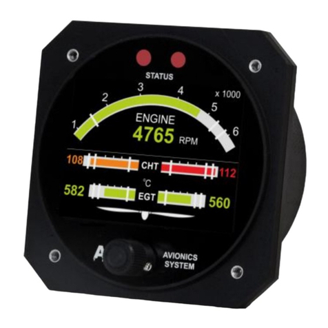
Fig. 1. EEM MOT 01 Display
This instrument is not certified by the FAA and EASA. Fitting of this
instrument to certified aircraft is subject to the rules and conditions
pertaining to such in your country. Please check with your local aviation
authorities if in doubt.
1. General information
This manual contains binding information, guidelines and warnings for safe
handling and maintenance of this particular instrument before installation,

Operators and Maintenance Manual
Display EEM MOT 01 FE03.04
Page
4/16
Copyright:
Auto & Aero Technologies Sp. z o.o.
Mazowiecka 10/5, 20-723 Lublin, Poland
■email: in[email protected] ■www.aatech.pl
during installation and in its operating phase. This document does not
contain rules and guidelines on operation of aircraft instruments at large.
Read the manual thoroughly before turning on the instrument and
precisely follow the instructions to install and configure it. This manual
does not replace instructions on installation, maintenance and operation
of this device in a particular airframe - these are to be prepared by the
user. Instructing the pilots and maintenance personnel on operation of the
instrument is also the responsibility of the user.
Operation of this instrument is the sole responsibility of the pilot in
command (PIC) of the aircraft. This person must be proficient and carry
a valid and relevant pilot’s license. This person has to make themselves
familiar with the operation of this instrument and the effect of any
possible failure or malfunction. Under no circumstances does the
manufacturer condone usage of this instrument for IFR flights.
This manual defines the scope of maintenance measures the user is
authorised to conduct on their own. Any repairs or modifications outside
this scope conducted by the user or contracted to a third party, as well as
using non-original parts and subassemblies voids the warranty, relieves the
supplier from any liability, making the instrument lose the status of the
product of Auto & Aero Technologies Sp. z o.o. with all the resulting
consequences.
2. Handling in transport and storage
1. The EEM MOT 01 monitor is bubble-wrapped to protect it against
vibration and other physical damage, and packed in a cardboard
box together with the warranty card.
2. The display must be stored and transported assuring that:
othe ambient temperature stays in the range of 10 40°C
othe ambient relative humidity stays in the range of 1090 %,
safe from condensation.
3. The display should be protected from water.

Operators and Maintenance Manual
Display EEM MOT 01 FE03.04
Page
5/16
Copyright:
Auto & Aero Technologies Sp. z o.o.
Mazowiecka 10/5, 20-723 Lublin, Poland
■email: in[email protected] ■www.aatech.pl
3. Installation
3.1. Environmental specifications
The EEM MOT 01 display has been designed to be installed in non-
hermetic cockpits of ultralight aircrafts of ceiling not exceeding 3 000 m
(10 000 ft). Acceptable range of operating parameters is listed below:
•Operating temperature: -20 oC 50 oC
•Short-term operating temperature: -25 oC 60 oC
•Humidity: 0 95 %, no condensation;
•Ambient air pressure: 45 105 kPa;
•Vibrations: <5 g at frequencies below 150 Hz;
3.2. Dimensions
Outline dimensions of the display are: 85 x 85 x 67 mm (width x height x
depth), Weight: 175 g.
Fig. 2. EEM MOT 01 Display outline drawing

Operators and Maintenance Manual
Display EEM MOT 01 FE03.04
Page
6/16
Copyright:
Auto & Aero Technologies Sp. z o.o.
Mazowiecka 10/5, 20-723 Lublin, Poland
■email: in[email protected] ■www.aatech.pl
3.3. Mounting
The display should be located conveniently within the pilot’s view in the
control panel in the cockpit. The diameter of the mounting hole to be cut
in the panel is 80mm. It is recommended that the display is installed from
the rear side the control panel. The display is to be fastened to the panel
by means of four M3 screws that are located symmetrically to the centre
of the mounting hole in the spacing of 62.9 mm (Fig. 3).
Fig. 3. Mounting hole and screw holes measurements (not to scale)
3.4. Power and wiring
The EEM MOT 01 display is powered from the aircraft power system.
Power specifications: nominal supply voltage 12V, acceptable supply
voltage range 8 ÷30V, current < 85mA.

Operators and Maintenance Manual
Display EEM MOT 01 FE03.04
Page
7/16
Copyright:
Auto & Aero Technologies Sp. z o.o.
Mazowiecka 10/5, 20-723 Lublin, Poland
■email: in[email protected] ■www.aatech.pl
The EEM MOT 01 display is connected to the system by in-built MOLEX
Ultra-Fit 3.5 mm 6 pin male connector located at the back of the
instrument. A schematic diagram of the connection is shown in Figure 4
and in Table 1.
The power supply (pins no. 5 and 6) requires 0.5 mm2wires.
Data bus (pins no. 3 and 4) requires twisted pair wires (2 x 0.5mm2)
according to DIN VDE 0814 (Fig. 4). Twisting should continue to the pins of
the connector.
Pins 1 and 2 are to be left unconnected.
Tab. 1. Connector pin assingment and pin insertion view
Pin number
Function
Connector schematic
1
Reserved (do
not connect)
2
Reserved (do
not connect)
3
RS A
4
RS B
5
GND
6
+12 V
Fig. 4. Wire twisting and connection

Operators and Maintenance Manual
Display EEM MOT 01 FE03.04
Page
8/16
Copyright:
Auto & Aero Technologies Sp. z o.o.
Mazowiecka 10/5, 20-723 Lublin, Poland
■email: in[email protected] ■www.aatech.pl
4. Operation and maintenance
The display is to be connected to EMS DAQ R2.
The front panel of EEM MOT 01 is composed of three elements: the
display, two status diodes (alert indication), and the encoder knob & push-
button for setting parameters (Fig. 5).
Rys. 5. Front panel of EEM MOT 01 Display
The EEM MOT 01 display displays values of flight parameters that are
either directly measured or calculated by the system. The display starts
automatically as the power is turned on.
As shown in Figure 6, the monitor with FE03.04 software version presents:
a) Oil pressure –in the upper left quarter of the display;
b) Oil temperature –in the bottom left quarter of the display;
c) Fuel level –bar graph on the right;
d) Flight time (measured from the last start of the engine) –
digits in the bottom left of the display;
e) Hobbs (total engine running time) - digits in the bottom right
of the display;
f) Voltage –the upper left of the display;
g) Number of recorded threshold crossings –the upper centre of
the display (e00);

Operators and Maintenance Manual
Display EEM MOT 01 FE03.04
Page
9/16
Copyright:
Auto & Aero Technologies Sp. z o.o.
Mazowiecka 10/5, 20-723 Lublin, Poland
■email: in[email protected] ■www.aatech.pl
Fig. 6. Display of the FE03.04 software version
On client’s request, warning and alarm threshold values may be set for
some of the above parameters according to the specification provided by
the aircraft supplier. Default threshold values are listed in Table 2.
Tab. 2. Parameters displayed by EEM MOT 01 FE03.04 display
Lp.
Parameter
Symbol/
name
in display
Unit
Range of
bar graph
indicator
Warning/alarm thresholds
Warning
Alarm
1
Fuel level
FUEL
L
0 70 l
-------
--------
2
Oil pressure
OIL p
Bar
0 –7,5 bar
from 1,0
to 2,5 bar#
from 5,0
to 7,0 bar
under
1,0 bar#
above
7 bar
2
Oil
temperature
OIL T
°C
0 –140 °C
from 50
to 60°C
from 110
to 130°C
under
50°C
above
130°C
3
Voltage in
electric
power
instalation
V
0 20 V
from 11
to 12V
from 14
to 15V
under 11V
above 15V
4
Flight time
FT
H:min
-------
--------
5
Total engine
running time
HOBBS
H:min
-------
--------
6
Number of
recorded
threshold
crossings
E

Operators and Maintenance Manual
Display EEM MOT 01 FE03.04
Page
10/16
Copyright:
Auto & Aero Technologies Sp. z o.o.
Mazowiecka 10/5, 20-723 Lublin, Poland
■email: in[email protected] ■www.aatech.pl
As the aircraft operates within “normal” range of the parameter in
question, the instrument displays values in green, and status diodes are
green. If the threshold level is being exceeded, the instrument informs the
pilot by changing both the colour of displayed figures and the colour of
status diodes. Exceeding the alarm threshold is additionally indicated by
the diodes flashing red. The pilot can switch off flashing by pushing the
encoder knob. Figure 7 presents the idea of colour codes and
warning/alarm indication.
Thus, information on the status of a flight parameter is presented in two
ways:
1) by means of the colour of two status diodes according to the
following colour code:
a) green –engine parameters within normal range;
b) orange –warning;
c) red –alarm;
2) by means of the colour of digits and bar graph (if applicable)
presenting the value of the parameter:
a. green –engine parameters within normal range;
b. orange –warning;
c. red –alarm;
The status information is obtained as a result of analysis conducted by the
instrument on the basis of digital input transmitted by the measurement
modules of the system.

Operators and Maintenance Manual
Display EEM MOT 01 FE03.04
Page
11/16
Copyright:
Auto & Aero Technologies Sp. z o.o.
Mazowiecka 10/5, 20-723 Lublin, Poland
■email: in[email protected] ■www.aatech.pl
Fig. 7. The idea of flight parameter status information
Both diodes are always of the same colour corresponding to the status of
the parameter that assumes “the worst” value.

Operators and Maintenance Manual
Display EEM MOT 01 FE03.04
Page
12/16
Copyright:
Auto & Aero Technologies Sp. z o.o.
Mazowiecka 10/5, 20-723 Lublin, Poland
■email: in[email protected] ■www.aatech.pl
5. Service, diagnostics and repairs
5.1. Service life
a) TBO of the display is not defined.
b) In the case of failure or error, the display must not be used any
more.
5.2. Checks
The following checks are recommended:
1) At pre-flight check:
a. Turn on the power to check if operational;
2) After 100 hours of flight:
a. Check the instrument’s electric connections;
b. Turn on the power on to check if operational.
5.3. Cleaning and conservation
The screen is to be buffed with water-damped soft cloth. Optionally, if very
dirty, can be cleaned with cloth sparingly damped with mild soap solution
or with a liquid dedicated for liquid crystal displays. Caution: the surface is
vulnerable to scratching.
5.4. Troubleshooting
a) If the screen stays blank when power is applied, turn off power
supply and verify power connection. Ensure that your power
supply is capable of supplying at least 8 volts, and no more than
30 V.

Operators and Maintenance Manual
Display EEM MOT 01 FE03.04
Page
13/16
Copyright:
Auto & Aero Technologies Sp. z o.o.
Mazowiecka 10/5, 20-723 Lublin, Poland
■email: in[email protected] ■www.aatech.pl
b) If no information is displayed when power is applied (Fig. 8), check
connection to measurement modules.
Fig. 8. Indication of no connection to measurement modules
c) In the case of the instrument’s failure or malfunction, turn power
off and on again.
d) If the above does not solve the problem, the display needs to be
replaced.
e) A defective instrument must not be used.
5.5. Repairs
Repairs and inspections of the instrument can be conducted only by its
manufacturer.
The display does not contain any user-serviceable parts. Unauthorized
repairs or modifications may result in permanent damage to the
equipment and void the warranty.
If the monitor fails, return the device to the Manufacturer with description
of the failure circumstances and symptoms.
5.6. Re-programming
Modifications to the instrument’s settings that are not possible to be
conducted by means of the encoder can be introduced by means of service
software provided by the Manufacturer and the dedicated diagnostic
interface.

Operators and Maintenance Manual
Display EEM MOT 01 FE03.04
Page
14/16
Copyright:
Auto & Aero Technologies Sp. z o.o.
Mazowiecka 10/5, 20-723 Lublin, Poland
■email: in[email protected] ■www.aatech.pl
The instrument’s firmware updates are to be conducted on the basis of the
bulletins published by the Manufacturer. The updates can be introduced
by means of service software provided by the Manufacturer and the
dedicated diagnostic interface.
5.7. Spare parts
The instrument does not contain any user-serviceable parts. The user is not
allowed to disassemble it nor replace any subassemblies.
6. Warranty
1. Auto & Aero Technologies Sp. z o.o. warrants this product to be free
from defects in materials and workmanship.
2. Auto & Aero Technologies Sp. z o.o. warrants proper operation of the
product if it is used in accordance with its intended purpose and in
accordance with the Operators and Maintenance Manual.
3. Auto & Aero Technologies Sp. z o.o. warrants this product for 12
months from date of purchase.
4. Auto & Aero Technologies Sp. z o.o. will, at its sole option, repair or
replace any components that fail in normal use. Such repairs or
replacement will be made at no charge to the customer for parts or
labour. The customer is, however, responsible for any transportation
cost. The repair or replacement will be completed within 30 days from
delivery of the product to Auto & Aero Technologies Sp. z o.o.
However, if the failure is possible to be eliminated by means of
updating the product’s firmware, and if Auto & Aero Technologies Sp.
z o.o. provides the customer with appropriate service tools, the
Customer will conduct firmware update by themselves.
5. Any warranty repair will extend the warranty for the time of the
repair.

Operators and Maintenance Manual
Display EEM MOT 01 FE03.04
Page
15/16
Copyright:
Auto & Aero Technologies Sp. z o.o.
Mazowiecka 10/5, 20-723 Lublin, Poland
■email: in[email protected] ■www.aatech.pl
6. If a valid warranty claim is lodged within months 7 to 12 after date of
purchase, the warranty extends for a further 6 months after
completion of the warranty repair.
7. This warranty does not cover failures due to:
a) mechanical damages and damages resulting from them,
b) unauthorised repairs,
c) damage caused by abuse or misuse,
d) unauthorised alterations to hardware or software.
8. The warranty does not cover claims that arise from the product
parameters unless they are different from values declared by Auto &
Aero Technologies Sp. z o.o.
9. The warranty does not cover activities that belong to normal
operation such as cleaning and conservation, operation checks, and
periodic inspections according to the Operators and Maintenance
Manual.
10. The Customer loses all rights arising from the warranty if the product’s
protective seals are found to be tampered with.
11. The rejection of Auto & Aero Technologies Sp. z o.o. to conduct
a warranty repair voids the warranty.

Operators and Maintenance Manual
Display EEM MOT 01 FE03.04
Page
16/16
Copyright:
Auto & Aero Technologies Sp. z o.o.
Mazowiecka 10/5, 20-723 Lublin, Poland
■email: in[email protected] ■www.aatech.pl
The information in this document is subject to change without notice and should
not be construed as commitment by Auto & Aero Technologies Sp. z o.o.
These technical data and the information embodied therein are the property of
Auto & Aero Technologies Sp. z o.o., and shall not, without prior written permission
of Auto & Aero Technologies Sp. z o.o., be disclosed in whole or in part to third
parties. This statement shall be included on any reproduction of these data, in
whole or in part. The Manual must remain with the engine/aircraft in case of sale.
Copyright 2020 © - all rights reserved.
Other product names in this documentation are used purely for ease of
identification and may be trademarks of the respective company or owner.
Approval of translation has been done to best knowledge and judgement - in any
case the original text in English language is authoritative.
This manual suits for next models
1
Table of contents
Other A&A Tech Monitor manuals

A&A Tech
A&A Tech EEM MOT 01 FL01.01 Installation instructions

A&A Tech
A&A Tech EEM MOT 01 FE01.07 Installation instructions

A&A Tech
A&A Tech EEM AM4 FE H01 Installation instructions

A&A Tech
A&A Tech EEM MOT 01 FE04.01 Installation instructions

A&A Tech
A&A Tech EEM MOT 01 FE03.02 Installation instructions

A&A Tech
A&A Tech EEM MOT 01 FL02.01 Installation instructions

A&A Tech
A&A Tech EEM MOT 01 Installation instructions