A&E Systems WeatherPro Oasis Elite User manual

1
DIAGNOSTIC
SERVICE MANUAL
Form No. 3308058.001 11/02
©2002Dometic Corporation
LaGrange, IN 46761

2
Contents PAGE NO.
WeatherPro & Oasis Elite Symptom/Cause ........................................... 3
SECTION 1- Wiring ..................................................................................4-5
1.1 12VDC Supply Wire ................................................................. 4
1.2 Wire From Control Box To Awning ................................................... 4
1.3 Wire Inside Hardware Channel (WeatherPro Only)......................... 4
1.4 Motor Connection & Motor............................................................... 4
1.5 Wire To Remote Switch ................................................................... 5
1.6 Wind Sensor Cable.......................................................................... 5
1.7 Ignition Interlock wire....................................................................... 5
SECTION 2- WeatherPro Wind Sensor ................................................... 6
2.1 Wind Sensor.................................................................................... 6
SECTION 3- Control Box.........................................................................6-7
3.1 Circuit Board ...................................................................................6-7
3.2 Control Box Rocker Switch .............................................................. 7
3.3 Wind Sensor Toggle Switch ............................................................. 7
3.4 Wiring Diagram ...............................................................................6-7
SECTION 4- Remote Switch .................................................................... 7
4.1 Remote Switch ................................................................................ 7
SECTION 5- Remote Key FOB ................................................................. 7
5.1 Remote Key FOB............................................................................. 7
5.2 FOB Programming ........................................................................... 8
SECTION 6- WeatherPro Auxiliary Cable ............................................... 8
6.1 Auxiliary Cable................................................................................. 8
SECTION 7- WeatherPro Emergency Retract Procedure.....................8-9
7.1 Emergency Retract Procedure .......................................................8-9
SECTION 8- WeatherPro Fabric, Roller Tube, Torsion Assembly
& Weathershield Replacement ..............................................................9-13
8.1 General Instructions ........................................................................ 9
8.2 Awning Removal............................................................................9-10
8.3 Left Hand Torsion Removal .......................................................... 10-11
8.4 Right Hand Drive Assembly Removal..............................................11
8.5 Fabric Removal From Roller Tube...................................................11
8.6 Weathershield Assembly Removal And Replacement .....................11
8.7 Re-install Fabric On Roller Tube..................................................... 12
8.8 Torsion Assembly Replacement....................................................12-13
8.9 Left Hand Torsion Assembly Winding ............................................. 13
SECTION 9- Wiring Diagram................................................................... 14
9.1 Wiring Diagram .............................................................................. 14

3
SYMPTON CAUSE LOCATION
1. Awning will not open 1. 12VDC Supply Wire Section 1.1
2. Fuse Section 3.1.3
3. Ignition Interlock (WeatherPro) Section 1.7 & 3.1.7
4. Wiring/Connections Section 1.2, 1.3, 1.4.1, 1.5 & 9.1
5. Wind (WeatherPro) Section 2.1 & 3.3
6. Circuit Board Wiring Section 3.1-3.4
7. Motor Section 1.4.2
2. Awning will not close 1. 12VDC Supply Wire Section 1.1
2. Fuse Section 3.1.3
3. Wiring/Connections Section 1.2, 1.3, 1.4, 1.5, & 9.1
4. Circuit Board Wiring Section 3.1-3.4
5. Motor Section 1.4.2
3. Awning works with remote switch 1. Distance Section 5.1
but not key FOB (WeatherPro Only) 2. Key FOB Battery Section 5.1
3. Key FOB Programming Section 5.2
4. Awning works with key FOB but not 1. Circuit Board Wiring Section 3.1.5 & 3.1.6
remote switch (WeatherPro Only) 2. Switch Section 4.1
5. Awning will open when ignition key is in 1. Wiring/Connections Section 1.7
the on position (WeatherPro Only) 2. Circuit Board Section 3.1.7
6. Awning works in opposite direction 1. Wiring/Connections Section 1.5
2. Circuit Board Wiring Section 3.1.5 & 3.1.6
3. Switch Section 4.1 & 3.2
7. WeatherPro awning works when Oasis 1. Wiring/Connections Section 1.2 & 9.1
Elite should or visa versa 2. Circuit Board Wiring Section 3.1.4
8. Awning does not close during high wind 1. Wind Sensor Switch Off Section 3.3
conditions 2. Wind Sensor Wiring Section 1.6 & 3.1.8
3. Wind Sensor Section 2.1
9. Beeping sound coming from control box 1. Wind Sensor Wiring Section 3.1.8
(WeatherPro Only) 2. Wind Sensor Section 2.1
10. Auxiliary Close/Open awning 1. No 12VDC in RV Section 6.1
(WeatherPro Only)
11. Emergency Close Awning 1. No 12VDC Available Section 7.1
(WeatherPro Only) 2. Awning Inoperable Section 7.1
12. Fabric, Roller Tube, Torsion Assembly Section 8.1- 8.9
and Weathershield Replacement
(WeatherPro Only)
4
SECTION 1 WIRING
1.1 12VDC Supply Wire
1.1.1 The 12VDC supply wire must be run from
the 12VDC supply source to the Control
Box. It is recommended that these wires
beRED+and Black–12gauge wires.This
needs to be on a separate 15 amp circuit.
See FIG. 1.1.
1.1.2 To ensure proper operation, the control
box must have a minimum of 12.5 VDC at
the control box during operation. Check
voltage output on the Red and Black wire
atthecontrolbox. If voltageisbelow 12.5,
check voltage at supply, If OK it may be
necessary to increase the wire size going
to the control box. See FIG. 1.1.
1.2 Wire From Control Box to Awning. Arm As-
sembly (WeatherPro) andAwning Motor (Oa-
sis Elite)
A Red and Black Wire (WeatherPro) Red/White
andBluewire (OasisElite)of adequatesizemust
be run between the control box and the awning.
To avoid voltage drop follow the chart below to
determining the proper size wire to be used.
Wire Length Wire Size
10' & Under 14 Gauge
11' to 30' 12 Gauge
Over 30' 10 Gauge
EXTEND
RETRACT
Awning
Control
FUSE INSIDE
WeatherPro
Main Arm
Right Side
Pig Tail to
Control Box
End
Pig Tail
for Motor
Oasis Elite
Motor
Black
Red
Red
Black
Red/White
Blue
Black
Red Blue
Red
FIG. 1.2
1.3 Wire Inside Hardware Channel (WeatherPro Only)
To make the connection between the wire run in
1.2 and the awning motor there is a cable run in
the hardware from the bottom to the top. Check
this wire for pinches or breaks. If wire is defec-
tive replace with new harness.
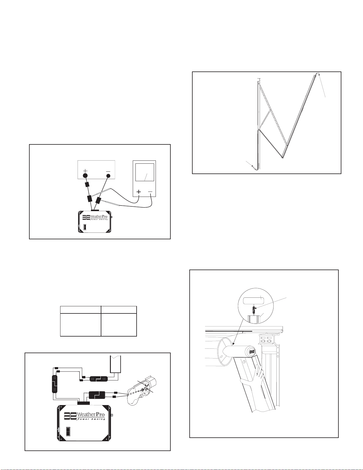
1.4 Motor Connection & Motor
1.4.1 The awning motor is connected to the
hardware at the top of the awning hard-
ware front channel. Make sure connec-
tion is tight and corrosion free.
1.4.2 Disconnect the motor from the hardware
connection. See FIG. 1.4. Apply DC volt-
age directly to the motor wire connector.
A minimum of 12.5 VDC is required to op-
erate the motor. If motor does not turn it is
defectiveandthedriveassemblymustbe
replaced.
FIG. 1.4
+12.5
VDC
EXTEND
RETRACT
Awning
Control
FUSE INSIDE
12VDC
Power Supply
15 AMP
Breaker
Red + Black-
FIG. 1.1
FIG. 1.3
Cable
Cable
Motor
Arm
WeatherPro
Motor Con-
nection
5
1.7 Ignition Interlock Wire
TheignitionInterlock wirewhencorrectly installed
will prevent the awning from opening when the
ignitionkeyisinthe onposition.This wireisrouted
between the ignition isolator (Pink) wire of the
control box to the ignition isolator of the vehicle.
It should be a 16 gauge wire. Make sure wire
connections are tight and corrosion free.
1.5 Wire To Remote Switch
The remote switch is connected to the control
box with three (3) 16 gauge wires. These are
Brown,Yellow,GreenforWeatherProandBrown/
White,Yellow/White,Green/WhiteforOasisElite.
The switch end of the wire will be connected to
the switch by means of 1/4" insulated tab con-
nectors. The control box end has a pig tail to
connectthecontrolbox tothesethreewires. See
switch for correct wiring. Make sure connections
are tight and corrosion free.
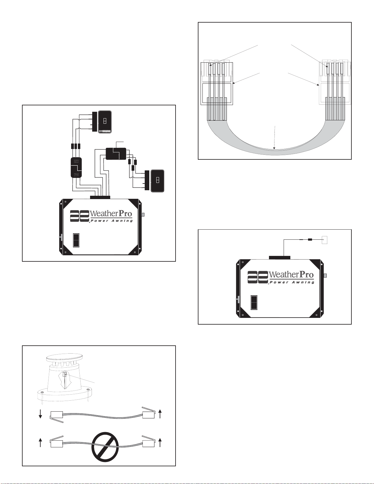
1.6 Wind Sensor Cable
The wind sensor is connected to the control box
with a FLAT four (4) conductor cable terminated
on both ends with an RJ-11 telephone connec-
tor. Maximum length is 18'. This cable is polarity
sensitive and must be assembled as shown. A
standard telephone cable will not work. Cable
can be checked with a Dometic 3107127.007
cable tester. If cable is found to be defective re-
place with a cable no longer than 18'
EXTEND
RETRACT
Awning
Control
FUSE INSIDE
WeatherPro
Remote
Switch
EXTEND
RETRACT
Pig Tail to
Remote Switch
Oasis Elite
Remote
Switch
Brown/White
Green/ White
Yellow/White
Green
Yellow
Brown
Green
Yellow
Brown
EXTEND
RETRACT
Brown
White
Green/ White
Yellow/White
Pig Tail to
Remote Switch
FIG. 1.5
FIG. 1.6
Red
4 Conductor
FLAT Cable
Connections
Black
Green
Yellow
Black
Green
Pin 1
RJ-11 Connector
Flat Four Conductor Cable
FIG. 1.6 cont.
Red
Yellow
EXTEND
RETRACT
Awning
Control
FUSE INSIDE
+Ignition
Isolator
Pink
FIG. 1.7
Table of contents
Other A&E Systems Accessories manuals


