AAON M3 Series Owner's manual

M3 SERIES
MODULAR AIR HANDLERS
INSTALLATION, OPERATION
&
MAINTENANCE
If the information in this manual is not
followed exactly, a fire or explosion
may result causing property damage,
personal injury or loss of life.
WARNING
FOR YOUR SAFETY
Do not store or use gasoline or other
flammable vapors and liquids in the
vicinity of this or any other appliance.
WARNING


3
Table of Contents
Section Page
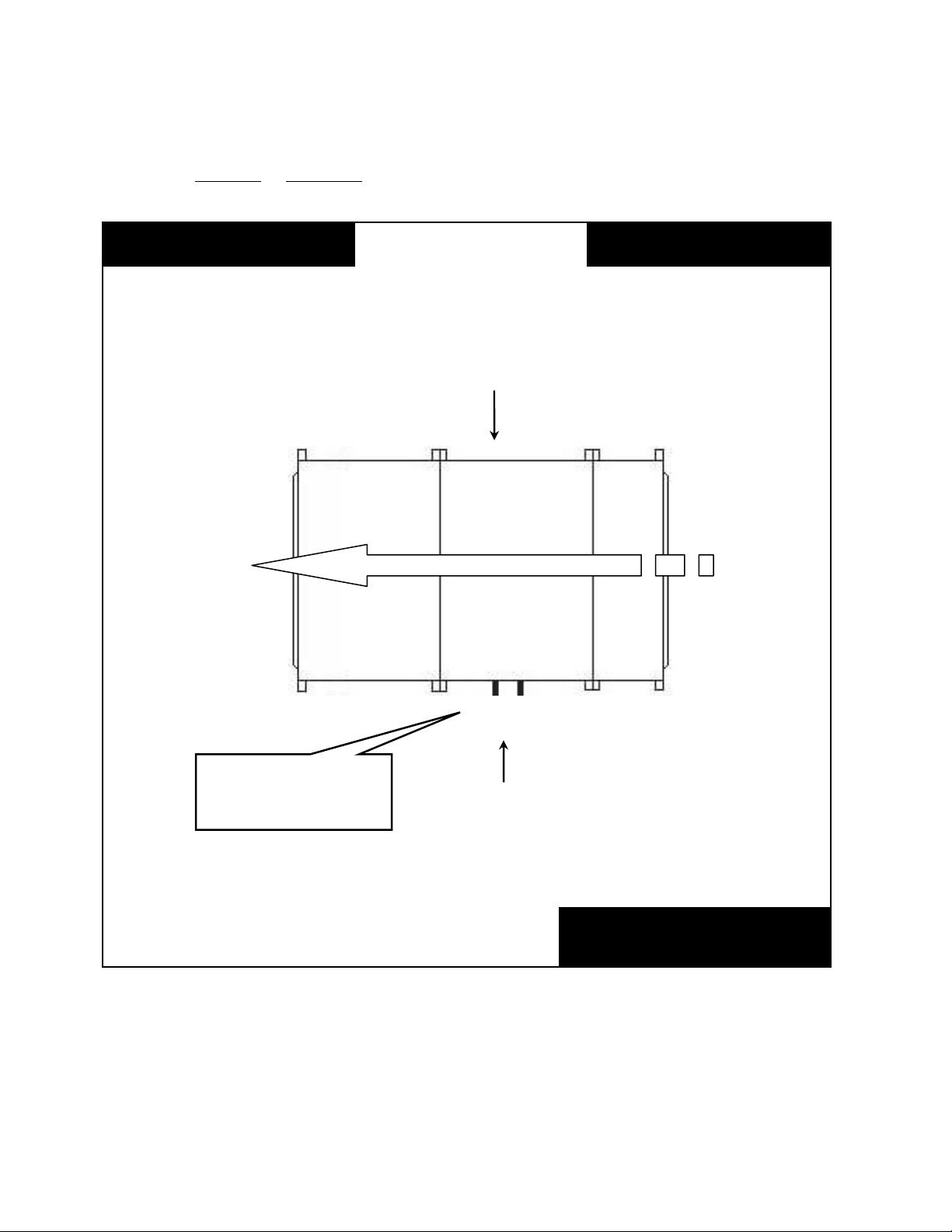
Unit Orientation………………………………………………………………………………………...5
Model Number Nomenclature……...……………………………………………….............................. 6
M3 Base Model Description……………………………………………………………………………7
Supply Fan Module Description………………………………………………………………………..9
Cooling/Preheat Coil Module Description………………………………………….............................. 12
Heating Coil Module Description………………………………………………………………………15
Blank Module Description……………….…….….................................................................................17
Filter Module Description ……………………………………………………………………………...19
Mixing Box/Economizer Module Description………............................................................................ 21
Discharge Module Description………………………………………………………………………… 23
Control Panel Module Description……………...................................................................................... 25
Exhaust Fan Module Description……………………………………………………………………… 27
Energy Recovery Module Description…................................................................................................ 30
Return Fan Module Description.............................................................................................................. 32
General Description……………………………………………………………………………………. 34
Important Safety Information………………………………………………………………………. 34
Receiving…………………………………………………………………………………………… 35
Storage……………………………………………………………………………………………… 36
Installation……………………………………………………………………………………………... 37
Location/Clearances………………………………………………………………………………... 37
Rigging……………………………………………………………………………………………... 37
Module Location…………………………………………………………………………………….38
Module Assembly…………………………………………………………………………………...38
Module Disassembly……………………………………………………………………………….. 41
Spring Isolation Adjustment………………………………………………………………………...42
Supply Air Wheel…………………………………………………………………………………... 42
Condensate Drains………………………………………………………………………………….. 43
Base Drains………………………………………………………………………………………….50
External Control Panel………………………………………………………………………………50
Electrical……………………………………………………………………………………………. 51
Panel Cutting……………………………………………………………………………………….. 51
Dampers/Actuators…………………………………………………………………………………. 52
Duct System…………………………………………………………………………………………53
Piping………………………………………………………………………………………………..53
Operation………………………………………………………………………………………………. 54
Startup Checklist…………………………………………………………………………………….54
Procedures…………………………………………………………………………………………...54
Commissioning……………………………………………………………………………………... 54
Air Balancing………………………………………………………………………………………..55
Water Balancing……………………………………………………………………………………. 55
Controls……………………………………………………………………………………………...55
Maintenance…………………………………………………………………………………………….55
Routine Maintenance………………………………………………………………………………..56
Blower Assembly……………………………………………………………………………………56
Coils/Drain Pan……………………………………………………………………………………...56
Doors/Panels………………………………………………………………………………………... 58
Filters……………………………………………………………………………………………….. 59
M3 Series Startup Form………………………………………………………………………………...61

4
It is the intent of AAON to provide accurate and current product information. However, in the
interest of product improvement, AAON reserves the right to change pricing, specifications,
and/or design of its products without notice, obligation or liability
Copyright © 2008 AAON, all rights reserved throughout the world.
AAON®& AAONAIRE®are registered trademarks of AAON, Inc., Tulsa, OK.
R57350 ·Rev. B ·080922

5
Unit Orientation
Determine left hand or right hand orientation (connections):
Consider the airflow to be
“hitting the back of your
M3 Air Handler Top View
Return AirSupply Air
Left Hand Side
Right Hand Side
Connections & service
access on left side for
left hand orientation
AIRFLOW
FilterCoilSupply Fan

6
Model Number Nomenclature
Base Model Number Individual Module Model Numbers
Identifies the main unit features and options. Identifies module configurations, features, and options.
MBA-101-0-00-0F0A0-000A0-0-0
FMB-102-0-00-B00C0-00000-0-0
CLA-103-A-00-CNCA0-00000-0-0
M3-0-094-134x119-3-A-A-A-0-A-0 : BMA-104-A-00-00000-00000-0-0
SFA-105-0-AA-CPTB0-00000-0-0
DPA-106-0-00-D0000-0000C-M-0
Complete Model Number
The complete unit model number consists of
a base model number followed by and series
of individual module numbers. In the
individual module model number, the three
numbers after the three letter Module ID
indicate the position of the module in final
air handler assembly, increasing in value
from the return/outside air section to the
discharge air section. In the above example,
the cooling coil module, CLA-103-A-00-
CNCA0-00000-0-0, would be the third
module in the air handler.

7
M3 Base Model Description
M3 0 06 0 10 8 09 9
1 2 -3 -4 5 6 -7 8 9 x10 11 12 -
BASE MODEL
Digit 1: Series
M = Modular
Digit 2: Generation
3 = 3rd Generation
Digit 3: TYPE
0 = Indoor Unit
A = Outdoor Unit
Digit 4, 5, 6: UNIT SIZE
032 = 32 ft2Coil
039 = 39 ft2Coil
045 = 45 ft2Coil
054 = 54 ft2Coil
060 = 60 ft2Coil
067 = 67 ft2Coil
074 = 74 ft2Coil
083 = 83 ft2Coil
094 = 94 ft2Coil
Digit 7, 8, 9, 10, 11, 12: CROSS SECTION
092 x 066 = 92” x 66”
092 x 079 = 92” x 79”
092 x 089 = 92” x 89”
108 x 089 = 108” x 89”
108 x 099 = 108” x 89”
122 x 096 = 122” x 96”
134 x 096 = 134” x 96”
134 x 107 = 134” x 107”
134 x 119 = 134” x 119”
Model Numbe
r

8
M3 Base Model Description
3B A B C B 0
13 -14 -15 -16 -17 -18 -19
Digit 13: VOLTAGE
2 = 230V/3Φ/60Hz
3 = 460V/3Φ/60Hz
4 = 575V/3Φ/60Hz
6 = 380-415V/3Φ/50Hz
8 = 208V/3Φ/60Hz
Digit 14: ASSEMBLY
A = Factory Assembled
B = Shipping Splits
Digit 15: WIRING
0 = No Wiring
A = Wiring, Motor Starters & Branch Fusing
Digit 16: ACCESSORIES
0 = None
A = 115V Outlet, Factory Wired (13Amp)
B = 115V Outlet, Field Wired (20 Amp)
Digit 17: CORROSION PROTECTION
0 = No Paint
A = Interior Corrosion Protection
B = Exterior Corrosion Protection
C = Shipping Shrink Wrap
D = Options A + B
E = Options A + C
F = Options B + C
G = Options A + B + C
Digit 18: BASE RAIL
0 = 6” High
A = 8” High
B = 10” High
Digit 19: TYPE
0 = None
U= Special Exterior Paint and Special Pricing
Authorization
X = Special Pricing Authorization and Standard Paint
Model Numbe
r

9
Supply Fan Module Description
SF A 00 0 0 00 CP H
1 2 3 -4 5 6 -7 -8 9 -10 11 12
Digit 1, 2, 3: MODULE ID
SFA = Supply Fan
SFB = Supply Fan with Flat Filter Bank
SFC = Supply Fan with External Control Panel
SFD = Supply Fan with Flat Filter Bank and External
Control Panel
Digit 4, 5, 6: POSITION
### = Level and Position of Module in Air Handler
Digit 7: CONNECTIONS
0 = No End Wall
B = Air Leaving Side End Wall
CONTROLS
Digit 8: TYPE
0 = No Wiring
A = Terminal Strip, Branch Fusing
B = VAV Controller, Motor Starters, Branch Fusing
C = CAV Controller, Motor Starters, Branch Fusing
D = MUA Controller, Motor Starters, Branch Fusing
Digit 9: MANUFACTURER
0 = No Wiring
A = Terminal Strip
B = WattMaster
D = WattMaster with Specials
BLOWERS AND MOTORS
Digit 10: QUANTITY
0 = 1 Blower with ODP Motor
A = 2 Blowers with ODP Motors
B = 3 Blowers with ODP Motors
C = 4 Blowers with ODP Motors
D = 1 Blower with TEFC Motor
E = 2 Blowers with TEFC Motors
F = 3 Blowers with TEFC Motors
G = 4 Blowers with TEFC Motors
Digit 11: TYPE
0 = Standard Efficiency
A = Premium Efficiency
B = Premium Eff with 1 VFD
C = Premium Eff with 1 VFD and Bypass
D = Premium Eff with Field Installed VFD
E = Premium Eff with 1 VFD Shipped Loose
F = Premium Eff with 2 VFDs
G = Premium Eff with 2 VFDs and Bypass
H = Premium Eff with 2 Field Installed VFDs
J = Premium Eff with 2 VFDs Shipped Loose
K = Premium Eff with 3 VFDs
L = Premium Eff with 3 VFDs and Bypass
M = Premium Eff with 3 Field Installed VFDs
N = Premium Eff with 3 VFDs Shipped Loose
P = Premium Eff with 4 VFDs
Q = Premium Eff with 4 VFDs and Bypass
R = Premium Eff with 4 Field Installed VFDs
S = Premium Eff with 4 VFDs Shipped Loose
Digit 12: HP
0 = 1 hp, 1170 rpm
A = 2 hp, 1170 rpm
B = 3 hp, 1170 rpm
C = 5 hp, 1170 rpm
D = 7.5 hp, 1170 rpm
E = 10 hp, 1170 rpm
F = 15 hp, 1170 rpm
G = 20 hp, 1170 rpm
H = 25 hp, 1170 rpm
J = 30 hp, 1170 rpm
K = 40 hp, 1170 rpm
L = 50 hp, 1170 rpm
M = 1 hp, 1760 rpm
N = 2 hp, 1760 rpm
P = 3 hp, 1760 rpm
Q = 5 hp, 1760 rpm
R = 7.5 hp, 1760 rpm
S = 10 hp, 1760 rpm
T = 15 hp, 1760 rpm
U = 20 hp, 1760 rpm
V = 25 hp, 1760 rpm
W= 30 hp, 1760 rpm
Y = 40 hp, 1760 rpm
Z = 50 hp, 1760 rpm
1 = 60 hp, 1760 rpm
Model Numbe
r

10
Supply Fan Module Description
GA AC B
13 14 -15 16 17
BLOWERS AND MOTORS
Digit 13: BLOWER
0 = 24” Diameter
A = 27” Diameter
B = 30” Diameter
C = 33” Diameter
D = 36.5” Diameter
E = 42.5” Diameter
Digit 14: BLOWER ISOLATION
0 = Springs (Unhoused 1” Deflection)
A = Springs (Unhoused 2” Deflection)
B = Springs (Seismic 1” Deflection)
C = Springs (Seismic 2” Deflection)
D = Option 0 + Backdraft Dampers
E = Option A + Backdraft Dampers
F = Option B + Backdraft Dampers
G = Option C + Backdraft Dampers
Digit 15: FILTER TYPE
0 = None
A = 2” Pleated, 30% Eff, MERV 7
B = 4” Pleated, 30” Eff, MERV 7
Digit 16: FILTER ACCESORIES
0 = None
A = Clogged Filter Switch
B = Magnehelic Gauge
C = Options A + B
D = Airflow Measurement
E = Options A + D
F = Options B + D
G = Options A + B + D
Digit 17: POWER SWITCH
0 = No Wiring
A = Power Block (No Power Switch)
B = 60 Amp Non-fused Disconnect Switch
C = 100 Amp Non-fused Disconnect Switch
D = 150 Amp Non-fused Disconnect Switch
E = 250 Amp Non-fused Disconnect Switch
F = 400 Amp Non-fused Disconnect Switch
G = 600 Amp Non-fused Disconnect Switch
H = 60 Amp Fused Disconnect Switch
J = 100 Amp Fused Disconnect Switch
K = 150 Amp Fused Disconnect Switch
L = 250 Amp Fused Disconnect Switch
M= 400 Amp Fused Disconnect Switch
N = 600 Amp Fused Disconnect Switch
Model Numbe
r

11
Supply Fan Module Description
0R B 0
18 19 -20 -21
Digit 18: CONTROL PANEL / OPENING
0 = None
A = Left Control Panel
B = Right Control Panel
C = Left Discharge Opening
D = Options B + C
E = Right Discharge Opening
F = Options A + E
G = Top Discharge Opening
H = Options A + G
I = Options B + G
Digit 19: MODULE ACCESSORIES
0 = None
A = Treadplate Floor
B = Base Drain
C = Marine Light
D = Door Window
F = Options A + B
G = Options A + C
H = Options A + D
J = Options B + C
K = Options B + D
L = Options C + D
P = Options A + B + C
Q = Options A + B + D
R = Options A + C + D
S = Options B + C + D
U = Options A + B + C + D
Digit 20: ACCESS
0 = Left Door, No Drain
A = Right Door, No Drain
B = Both Doors, No Drain
C = Left Door, Left Drain
D = Left Door, Right Drain
E = Left Door, Both Drains
F = Right Door, Left Drain
G = Right Door, Right Drain
H = Right Door, Both Drains
J = Both Doors, Left Drain
K = Both Doors, Right Drain
L = Both Doors, Both Drains
Digit 21: SPECIAL
0 = Standard
A = Stainless Steel Interior
B = Stainless Steel Exterior
C = Options A + B
X = Special Pricing Authorization
Y = Options A + X
Z = Options B + X
1 = Options A + B + X
Model Numbe
r

12
Cooling/Preheat Coil Module Description
CL D 00 0 AH0 AA
1 2 3 -4 5 6 -7 -8 9 -10 11
Digit 1, 2, 3: MODULE ID
CLA = Chilled Water Coils, External Connection,
Standard Drain Pan (30.5”)
CLC = Chilled Water Coils, Hydronic Preheat,
External Connection, Standard Drain Pan (30.5”)
CLD = DX Coils
CLE = DX Coils, Hot Gas Reheat
CLF = DX Coils, Hydronic Preheat
CLG = DX Coils, Hot Gas Reheat, Hydronic Preheat
CLH = Chilled Water Coils, External Connection,
Short Drain Pan (9”)
CLJ = Chilled Water Coils, Hydronic Preheat,
External Connection, Short Drain Pan (9”)
Digit 4, 5, 6: POSITION
### = Level and Position of Module in Air Handler
Digit 7: COMPARTMENT PRESSURIZATION
0 = Blow-Thru, No End Wall
A = Draw-Thru, No End Wall
B = Blow-Thru, Air Leaving Side End Wall
Digit 8: BLANK
0 = Standard
Digit 9: BLANK
0 = Standard
COOLING COIL
Digit 10: ROWS
0 = 4 Rows, 1/2” Tubes, 50/50 Split
A = 6 Rows, 1/2” Tubes, 50/50 Split
B = 8 Rows, 1/2” Tubes, 50/50 Split
C = 4 Rows, 5/8” Tubes, 50/50 Split
D = 6 Rows, 5/8” Tubes, 50/50 Split
E = 8 Rows, 5/8” Tubes, 50/50 Split
Digit 11: FPI
0 = 8 FPI, 0.0060” Fin Thick, 0.017” Tube Wall
A = 10 FPI, 0.0060” Fin Thick, 0.017” Tube Wall
B = 12 FPI, 0.0060” Fin Thick, 0.017” Tube Wall
C = 8 FPI, 0.0075” Fin Thick, 0.017” Tube Wall
D = 10 FPI, 0.0075” Fin Thick, 0.017” Tube Wall
E = 12 FPI, 0.0075” Fin Thick, 0.017” Tube Wall
F = 8 FPI, 0.0100” Fin Thick, 0.017” Tube Wall
G = 10 FPI, 0.0100” Fin Thick, 0.017” Tube Wall
H = 12 FPI, 0.0100” Fin Thick, 0.017” Tube Wall
J = 8 FPI, 0.0060” Fin Thick, 0.025” Tube Wall
K = 10 FPI, 0.0060” Fin Thick, 0.025” Tube Wall
L = 12 FPI, 0.0060” Fin Thick, 0.025” Tube Wall
M = 8 FPI, 0.0075” Fin Thick, 0.025” Tube Wall
N = 10 FPI, 0.0075” Fin Thick, 0.025” Tube Wall
P = 12 FPI, 0.0075” Fin Thick, 0.025” Tube Wall
Q = 8 FPI, 0.0100” Fin Thick, 0.025” Tube Wall
R = 10 FPI, 0.0100” Fin Thick, 0.025” Tube Wall
S = 12 FPI, 0.0100” Fin Thick, 0.025” Tube Wall
T = 8 FPI, 0.0060” Fin Thick, 0.035” Tube Wall
U = 10 FPI, 0.0060” Fin Thick, 0.035” Tube Wall
V = 12 FPI, 0.0060” Fin Thick, 0.035” Tube Wall
W = 8 FPI, 0.0075” Fin Thick, 0.035” Tube Wall
Y = 10 FPI, 0.0075” Fin Thick, 0.035” Tube Wall
Z = 12 FPI, 0.0075” Fin Thick, 0.035” Tube Wall
1 = 8 FPI, 0.0100” Fin Thick, 0.035” Tube Wall
2 = 10 FPI, 0.0100” Fin Thick, 0.035” Tube Wall
3 = 12 FPI, 0.0100” Fin Thick, 0.035” Tube Wall
Model Numbe
r

13
Cooling/Preheat Coil Module Description
00 A CA
12 13 14 -15 16
COOLING COIL
Digit 12: CIRCUITING
0 = Full Serpentine
A = Half Serpentine
B = 1 1/2 Serpentine
C = Double Serpentine
D = DX Single Systems
E = DX Two Interlaced Systems
Digit 13: COATING
0 = Galvanized Coil Casings
A = Polymer E-Coated Coils
B = Stainless Steel Coil Casings
C = Stainless Steel Coil Casings, Copper Fins
Digit 14: ACCESSORIES
0 = None
A = UV Lights
B = 2” Pleated Filters, 30% Eff, MERV 7, Coil Inlet
C = 4” Pleated Filters, 30% Eff, MERV 7, Coil Inlet
D = Options A + B
E = Options A + C
Preheat Coil
Digit 15: ROWS
0 = No Preheat Coil
A = 1 Rows, 1/2” Tubes
B = 2 Rows, 1/2” Tubes
C = 1 Rows, 5/8” Tubes
D = 2 Rows, 5/8” Tubes
Digit 16: FPI
0 = No Preheat Coil
A = 8 FPI, 0.0060” Fin Thick, 0.017” Tube Wall
B = 10 FPI, 0.0060” Fin Thick, 0.017” Tube Wall
C = 12 FPI, 0.0060” Fin Thick, 0.017” Tube Wall
D = 8 FPI, 0.0075” Fin Thick, 0.017” Tube Wall
E = 10 FPI, 0.0075” Fin Thick, 0.017” Tube Wall
F = 12 FPI, 0.0075” Fin Thick, 0.017” Tube Wall
G = 8 FPI, 0.0100” Fin Thick, 0.017” Tube Wall
H = 10 FPI, 0.0100” Fin Thick, 0.017” Tube Wall
J = 12 FPI, 0.0100” Fin Thick, 0.017” Tube Wall
K = 8 FPI, 0.0060” Fin Thick, 0.025” Tube Wall
L = 10 FPI, 0.0060” Fin Thick, 0.025” Tube Wall
M = 12 FPI, 0.0060” Fin Thick, 0.025” Tube Wall
N = 8 FPI, 0.0075” Fin Thick, 0.025” Tube Wall
P = 10 FPI, 0.0075” Fin Thick, 0.025” Tube Wall
Q = 12 FPI, 0.0075” Fin Thick, 0.025” Tube Wall
R = 8 FPI, 0.0100” Fin Thick, 0.025” Tube Wall
S = 10 FPI, 0.0100” Fin Thick, 0.025” Tube Wall
T = 12 FPI, 0.0100” Fin Thick, 0.025” Tube Wall
U = 8 FPI, 0.0060” Fin Thick, 0.035” Tube Wall
V = 10 FPI, 0.0060” Fin Thick, 0.035” Tube Wall
W = 12 FPI, 0.0060” Fin Thick, 0.035” Tube Wall
Y = 8 FPI, 0.0075” Fin Thick, 0.035” Tube Wall
Z = 10 FPI, 0.0075” Fin Thick, 0.035” Tube Wall
1 = 12 FPI, 0.0075” Fin Thick, 0.035” Tube Wall
2 = 8 FPI, 0.0100” Fin Thick, 0.035” Tube Wall
3 = 10 FPI, 0.0100” Fin Thick, 0.035” Tube Wall
4 = 12 FPI, 0.0100” Fin Thick, 0.035” Tube Wall
Model Numbe
r

14
Cooling/Preheat Coil Module Description
C0 G B 0
17 18 19 -20 -21
Digit 17: TYPE
0 = No Preheat Coil
A = Hot Water, Full Serpentine (2 Rows Only)
B = Hot Water, Half Serpentine
C = Hot Water, Quarter Serpentine
D = Steam Distributing
Digit 18: COATING
0 = No Preheat Coil
A = Galvanized Coil Casing
B = Polymer E-Coated Coil
C = Stainless Steel Coil Casing
D = Stainless Steel Coil Casing, Copper Fins
Digit 19: MODULE ACCESSORIES
0 = None
A = Marine Light
B = Door Window
C = Options A + B
Digit 20: ACCESS
0 = Left Door, Left Drain, Left Coil Connections
A = Left Door, Left Drain, Right Coil Connections
B = Left Door, Right Drain, Left Coil Connections
C = Left Door, Right Drain, Right Coil Connections
D = Left Door, Both Drains, Left Coil Connections
E = Left Door, Both Drains, Right Coil Connections
F = Right Door, Left Drain, Left Coil Connections
G = Right Door, Left Drain, Right Coil Connections
H = Right Door, Right Drain, Left Coil Connections
J = Right Door, Right Drain, Right Coil Connections
K = Right Door, Both Drains, Left Coil Connections
L = Right Door, Both Drains, Right Coil Connections
M = Both Doors, Left Drain, Left Coil Connections
N = Both Doors, Left Drain, Right Coil Connections
P = Both Doors, Right Drain, Left Coil Connections
Q = Both Doors, Right Drain, Right Coil Connection
R = Both Doors, Both Drains, Left Coil Connections
S = Both Doors, Both Drains, Right Coil Connections
Digit 21: SPECIAL
0 = Standard
A = Stainless Steel Interior
B = Stainless Steel Exterior
C = Options A + B
X = Special Pricing Authorization
Y = Options A + X
Z = Options B + X
1 = Options A + B + X
Model Numbe
r

15
Heating Coil Module Description
HC D 00 0 AHE BB
1 2 3 -4 5 6 -7 -8 9 -10 11
Digit 1, 2, 3: MODULE ID
HCA = Hot Water Coil, External Connections
HCB = Steam Coil, External Connections
HCC = Electric Heat
HCD = Hot Water Coil with Internal Face and
Bypass Dampers
HCE = Hot Water Coil with External Face and
Bypass Dampers
HCF = Integral Face and Bypass Hot Water Coil
HCG = Steam Coil with Internal Face and Bypass
Dampers
HCH = Steam Coil with External Face and Bypass
Dampers
HCJ = Integral Face and Bypass Steam Coil
Digit 4, 5,6: POSITION
### = Level and Position of Module in Air Handler
Digit 7: COMPARTMENT PRESSURIZATION
0 = Blow Thru
A = Draw Thru
ELECTRIC HEAT
Digit 8: CAPACITY
0 = No Electric Heat
A = 40 kW
B = 80 kW
C = 120 kW
D = 160 kW
E = 200 kW
F = 240 kW
G = 280 kW
H = 320 kW
J = 360 kW
K = 400 kW
L = 440 kW
M = 480 kW
Digit 9: STAGING
0 = No Electric Heat
A = 2 Stage
B = 3 Stage
C = 4 Stage
D = 6 Stage
E = 8 Stage
F = 12 Stage
G = SCR Controlled - Potentiometer
H = SCR Controlled - 0-10VDC External Control
Heating Coil
Digit 10: SIZE
0 = No Heating Coil
A = Size A
B = Size B
C = Size C
D = Size D
Digit 11: ROWS
0 = No Heating Coil
A = 1 Row, 1/2” Tubes
B = 2 Rows, 1/2” Tubes
C = 1 Row, 5/8” Tubes
D = 2 Rows, 5/8” Tubes
Model Numbe
r

16
Heating Coil Module Description
CA A 00 0 0 0 B 0
12 13 14 -15 16 17 18 19 -20 -21
Heating Coil
Digit 12: FPI
0 = No Heating Coil
A = 8 FPI, 0.0060” Fin Thick, 0.017” Tube Wall
B = 10 FPI, 0.0060” Fin Thick, 0.017” Tube Wall
C = 12 FPI, 0.0060” Fin Thick, 0.017” Tube Wall
D = 8 FPI, 0.0075” Fin Thick, 0.017” Tube Wall
E = 10 FPI, 0.0075” Fin Thick, 0.017” Tube Wall
F = 12 FPI, 0.0075” Fin Thick, 0.017” Tube Wall
G = 8 FPI, 0.0100” Fin Thick, 0.017” Tube Wall
H = 10 FPI, 0.0100” Fin Thick, 0.017” Tube Wall
J = 12 FPI, 0.0100” Fin Thick, 0.017” Tube Wall
K = 8 FPI, 0.0060” Fin Thick, 0.025” Tube Wall
L = 10 FPI, 0.0060” Fin Thick, 0.025” Tube Wall
M = 12 FPI, 0.0060” Fin Thick, 0.025” Tube Wall
N = 8 FPI, 0.0075” Fin Thick, 0.025” Tube Wall
P = 10 FPI, 0.0075” Fin Thick, 0.025” Tube Wall
Q = 12 FPI, 0.0075” Fin Thick, 0.025” Tube Wall
R = 8 FPI, 0.0100” Fin Thick, 0.025” Tube Wall
S = 10 FPI, 0.0100” Fin Thick, 0.025” Tube Wall
T = 12 FPI, 0.0100” Fin Thick, 0.025” Tube Wall
U = 8 FPI, 0.0060” Fin Thick, 0.035” Tube Wall
V = 10 FPI, 0.0060” Fin Thick, 0.035” Tube Wall
W = 12 FPI, 0.0060” Fin Thick, 0.035” Tube Wall
Y = 8 FPI, 0.0075” Fin Thick, 0.035” Tube Wall
Z = 10 FPI, 0.0075” Fin Thick, 0.035” Tube Wall
1 = 12 FPI, 0.0075” Fin Thick, 0.035” Tube Wall
2 = 8 FPI, 0.0100” Fin Thick, 0.035” Tube Wall
3 = 10 FPI, 0.0100” Fin Thick, 0.035” Tube Wall
4 = 12 FPI, 0.0100” Fin Thick, 0.035” Tube Wall
Digit 13: TYPE
0 = No Heating Coil
A = Hot Water, Full Serpentine (2 Rows Only)
B = Hot Water, Half Serpentine
C = Hot Water, Quarter Serpentine
D = Steam Distributing
Digit 14: COATING
0 = No Heating Coil
A = Galvanized Coil Casing
B = Polymer E-Coated Coil
C = Stainless Steel Coil Casing
D = Stainless Steel Coil Casing, Copper Fins
Digit 15: BLANK
0 = Standard
Digit 16: BLANK
0 = Standard
Digit 17: BLANK
0 = Standard
Digit 18: BLANK
0 = Standard
Digit 19: MODULE ACCESORIES
0 = None
A = Heating Coil Drain Pan
Digit 20: ACCESS
0 = No Drain, Left Coil Connections
A = No Drain, Right Coil Connections
B = Left Drain, Left Coil Connections
C = Left Drain, Right Coil Connections
D = Right Drain, Left Coil Connections
E = Right Drain, Right Coil Connections
F = Both Drain, Left Coil Connections
G = Both Drain, Right Coil Connections
H = No Drain, No Coil Connections
Digit 21: SPECIAL
0 = Standard
A = Stainless Steel Interior
B = Stainless Steel Exterior
C = Options A + B
X = Special Pricing Authorization
Y = Options A + X
Z = Options B + X
1 = Options A + B + X
Model Numbe
r

17
Blank Module Description
BM C 00 0 A 00 00 0 0
1 2 3 -4 5 6 -7 -8 9 -10 11 12 13
Digit 1, 2, 3: MODULE ID
BMA = 2’ Access Section
BMB = 2.5’ Access Section
BMC = 3’ Access Section
BMD = 4’ Access Section
Digit 4, 5, 6: POSTION
### = Level and Position of Module in Air Handler
Digit 7: COMPARTMENT PRESSURIZATION
0 = Blow-Thru, No End Wall
A = Draw-Thru, No End Wall
B = Blow-Thru, Air Leaving Side End Wall
Digit 8: BLANK
0 = Standard
Digit 9: BLANK
0 = Standard
Digit 10: DRAIN PAN
0 = None
A = Stainless Steel Drain Pan
Digit 11: SOUND ATTENATOR
0 = None
Digit 12: AIR BLENDER
0 = None
Digit 13: HUMIDIFIER GRID
0 = None
Model Numbe
r

18
Blank Module Description
000 0 0Q B 0
14 -15 16 17 18 19 -20 -21
Digit 14: BLANK
0 = Standard
Digit 15: BLANK
0 = Standard
Digit 16: BLANK
0 = Standard
Digit 17: BLANK
0 = Standard
Digit 18: BLANK
0 = Standard
Digit 19: MODULE ACCESSORIES
0 = None
A = Treadplate Floor
B = Base Drain
C = Marine Light
D = Door Window
F = Options A + B
G = Options A + C
H = Options A + D
J = Options B + C
K = Options B + D
L = Options C + D
P = Options A + B + C
Q = Options A + B + D
R = Options A + C + D
S = Options B + C + D
U = Options A + B + C + D
Digit 20: ACCESS
0 = Left Door, No Drain
A = Right Door, No Drain
B = Both Doors, No Drain
C = Left Door, Left Drain
D = Left Door, Right Drain
E = Left Door, Both Drains
F = Right Door, Left Drain
G = Right Door, Right Drain
H = Right Door, Both Drains
J = Both Doors, Left Drain
K = Both Doors, Right Drain
L = Both Doors, Both Drains
M = No Door, No Drain
N = No Door, Left Drain
P = No Door, Right Drain
Q = No Door, Both Drains
Digit 21: SPECIAL
0 = Standard
A = Stainless Steel Interior
B = Stainless Steel Exterior
C = Options A + B
X = Special Pricing Authorization
Y = Options A + X
Z = Options B + X
1 = Options A + B + X
Model Numbe
r

19
Filter Module Description
FM A 00 0 A 00 A
1 2 3 -4 5 6 -7 -8 9 -10
Digit 1, 2, 3: MODULE ID
FMA = Flat Filter Bank
FMB = Angle Filter Bank
FMC = Flat Cartridge Filter Bank
FMD = Staggered Cartridge Filter Bank
FME = Bag Filter Bank
FMF = HEPA Filter Bank
Digit 4, 5, 6: POSTION
### = Level and Position of Module in Air Handler
Digit 7: BLANK
0 = Standard
Digit 8: BLANK
0 = Standard
Digit 9: BLANK
0 = Standard
Digit 10: PREFILTER
0 = None
A = 2” Pleated, 30% Eff, MERV 7
B = 4” Pleated, 30% Eff, MERV 7
Model Numbe
r

20
Filter Module Description
BC A 0 00 0 0 0 0 0
11 12 13 14 -15 16 17 18 19 -20 -21
Digit 11: FINAL FILTER
0 = None
A = 4” Cartridge Filter
B = 12” Cartridge Filter
C = 30“ Bag Filter
Digit 12: FINAL FILTER EFFICIENCY
0 = None
A = MERV 11 (65% Eff)
B = MERV 13 (85% Eff)
C = MERV 14 (95% Eff)
Digit 13: ACCESSORIES
0 = None
A = Clogged Filter Switch
B = Magnehelic Gauge
C = Options A + B
Digit 14: BLANK
0 = Standard
Digit 15: BLANK
0 = Standard
Digit 16: BLANK
0 = Standard
Digit 17: BLANK
0 = Standard
Digit 18: BLANK
0 = Standard
Digit 19: BLANK
0 = Standard
Digit 20: BLANK
0 = Standard
Digit 21: SPECIAL
0 = Standard
A = Stainless Steel Interior
B = Stainless Steel Exterior
C = Options A + B
X = Special Pricing Authorization
Y = Options A + X
Z = Options B + X
1 = Options A + B + X
Model Numbe
r
Other manuals for M3 Series
1
Table of contents
Other AAON Air Handler manuals

AAON
AAON M3 Series Owner's manual

AAON
AAON RN Series Owner's manual

AAON
AAON F1-060 Instruction manual

AAON
AAON RM Series Service manual

AAON
AAON SA-028 Owner's manual

AAON
AAON RZ Series Owner's manual

AAON
AAON RQ NextGen Series Owner's manual

AAON
AAON RZ Series Owner's manual

AAON
AAON H3 Series Owner's manual

AAON
AAON M2 Series Owner's manual