AAON RQ SERIES User manual

RQ SERIES
Variable Speed Scroll Compressor
Supplement

2
Table of Contents
Variable Speed Scroll Compressor Supplement ............................................................................. 1
RQ Series Variable Speed Compressor Components ................................................................. 5
Introduction..................................................................................................................................... 8
Variable Speed Scroll Compressors................................................................................................ 8
Product Description .................................................................................................................... 8
Compressor Motor ...................................................................................................................... 8
Oil Pump ..................................................................................................................................... 8
Compressor Temperature Protection .......................................................................................... 8
Oil Recovery ............................................................................................................................... 8
Motor Protection ......................................................................................................................... 8
Starting and Stopping Routine .................................................................................................... 8
Oil Type ...................................................................................................................................... 9
Maximum Tilt Angle .................................................................................................................. 9
Contaminant Control................................................................................................................... 9
Discharge Check Valve............................................................................................................... 9
Electrical Troubleshooting........................................................................................................ 10
Three Phase Series Variable Speed Drives................................................................................... 11
Product Description .................................................................................................................. 11
Theory of Drive Operation........................................................................................................ 11
Nomenclature............................................................................................................................ 11
Temperature & Humidity.......................................................................................................... 11
Power On/Off............................................................................................................................ 11
Communication Setting ............................................................................................................ 11
Input Voltage and Input Current ............................................................................................... 12
Power Factor Correction........................................................................................................... 12
Speed Control............................................................................................................................ 12
Fault Clearing............................................................................................................................ 12
Status Indication........................................................................................................................ 12
LED for COMMS MCU ........................................................................................................... 12
Drive Over Temperature Protection.......................................................................................... 13
Power Interrupt ......................................................................................................................... 13
Air Cooled Heat Exchanger ...................................................................................................... 13
Foldback.................................................................................................................................... 13
Troubleshooting ............................................................................................................................ 13
Variable Speed Compressor Temperature Control ....................................................................... 21
Modular Silicon Expansion Valve and Universal SuperHeat Controller/Sensor Hardware
Installation..................................................................................................................................... 22
Additional Product Markings for USHC-G1.3b and USHS-G1.3b.......................................... 22
About the MSEV and USHX.................................................................................................... 22
Mechanical Installation............................................................................................................. 24
Electrical Wiring....................................................................................................................... 28
Troubleshooting ........................................................................................................................ 32

3
Index of Tables and Figures
Tables:
Table 1 - Troubleshooting –Fault and Protection ........................................................................ 14
Table 2 - Communication Connector Pin Definition.................................................................... 18
Table 3 - Sensor Connector Pin Definition................................................................................... 18
Table 4 - Ramp Up Procedure ...................................................................................................... 19
Table 5 - Ramp Down Sequence .................................................................................................. 19
Table 6 - Input Current Foldback.................................................................................................. 20
Table 7 - Output Current Foldback............................................................................................... 20
Table 8 - Inverter Temperature Feedback..................................................................................... 20
Table 9 - USHX and Wiring Harness Pin Assignments ............................................................... 23
Figures:
Figure 1 –Variable Speed Scroll Design Features ....................................................................... 10
Figure 2 –Motor Winding Diagram ............................................................................................. 10
Figure 3- Electronics Nomenclature ............................................................................................. 16
Figure 4 - U.S. Drive Model Wiring Diagram.............................................................................. 17
Figure 5 - U.S. Wiring Diagram ................................................................................................... 17
Figure 6 - WattMaster VCC-X Controller and Refrigeration System Control Module ............... 21
Figure 7 - Modular Silicon Expansion Valve ............................................................................... 22
Figure 8 - USHX........................................................................................................................... 22
Figure 9 - USHZ Wiring Harness ................................................................................................. 22
Figure 10 - MSEV and USHC installation schematic .................................................................. 24
Figure 11 - MSEV installation orientation.................................................................................... 25
Figure 12 - USHX installation orientation on a horizontal copper line........................................ 26
Figure 13 - USHX installation orientation on vertical copper line............................................... 26
Figure 14 - Brazed access fitting .................................................................................................. 26
Figure 15 - Installed USHX with attached 10-pin wiring harness................................................ 27
Figure 16 - Thermistor installation at evaporator outlet ............................................................... 27
Figure 17 - Insulation secured to the thermistor ........................................................................... 28
Figure 18 - Class 2 DC and AC power sources ............................................................................ 29
Figure 19 - Single USHC-MSEV or single USHS wiring diagram.............................................. 30
Figure 20 - USHX-to-RS485 converter connection...................................................................... 31
Figure 21 - MSEV electrical connections..................................................................................... 31
V83980 ·Rev. A ·170111

4

5
RQ Series Variable Speed Compressor Components
Variable Speed Compressor
Inverter
Electronic Expansion Valve
WattMaster VCC-X Controls
EC Motor Automation Control Unit

6
Variable Speed Compressor
Inverter
WattMaster VCC-X Controls
Condenser Fan EC Motor Automation
Control Unit
Electronic Expansion Valve Controller

7
Example Wiring Diagram showing WattMaster Refrigeration System Module for Variable Speed
Compressors, Copeland Inverter, Electronic Expansion Valve, and Variable Speed Condenser
Fan Control

8
Introduction
This document provides instructions on how
the variable speed scroll compressor and
inverter drive are applied to a variable speed
compressor in a safe and reliable manner.
The variable speed scroll compressor will be
referred to throughout this document as the
“variable speed compressor” or the
“compressor”. The inverter drive will be
referred to throughout this document as the
“inverter drive”or simply the “drive”.
Variable Speed Scroll Compressors
Product Description
The variable speed compressor has a speed
range of 900 (refer to operating envelope for
low speed operation) to 5000 revolutions per
minute and is intended for use in
commercial air conditioning, chiller, and
heat pump applications. The variable speed
scrolls utilize three-phase brushless
permanent magnet (BPM) motors. The
compressors have been qualified for use
with drives which have been developed and
qualified for BPM motor-compressors.
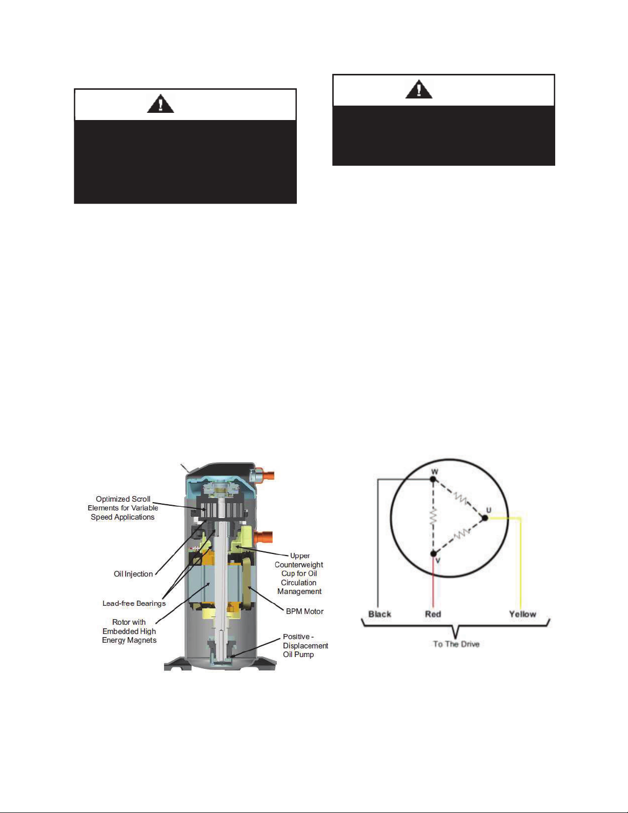
Compressor Motor
The brushless permanent magnet (BPM)
motor in the variable speed scroll consists of
a three-phase stator and a rotor embedded
with high energy permanent magnets. The
input voltage is a series of pulses of varying
frequency at 120 degree intervals between
phases.
Oil Pump
The variable speed scroll is equipped with
an oil pump to ensure an adequate supply of
oil to the bearing system throughout the
operating speed range of 900 to 5000 RPM.
Compressor Temperature Protection
A discharge line thermistor must be used to
protect the compressor. The drive will shut
down the compressor when the thermistor
temperature exceeds 275°F (135°C).
Oil Recovery
An oil recovery cycle is required if
compressor speed is below 1,800 rpm for 2
hours. When this occurs, the unit controls
will increase the compressor speed to 3,600
rpm for five minutes.
Motor Protection
The drive includes motor protection features
for the compressor. The drive sets the
maximum current limit, low voltage fold
back which allows the compressor to ride
through low voltage situations, which helps
keep the compressor running to avoid
nuisance trips.
Starting and Stopping Routine
The drive controls the starting and stopping
routine of the variable speed scroll. This
routine allows soft starting and controlled
stopping, an advantage over traditional on-
off control of fixed capacity units. Please
refer to Table 4 for an exact explanation of
the starting and stopping process.
The variable speed scroll compressor
incorporates a fluid brake design to help
mitigate reverse rotation during shutdown. A
momentary reverse rotation sound may be
heard.

9
Oil Type
Variable speed scrolls are charged with
polyolester (POE) oil. See the compressor
nameplate for the original oil charge. A
complete recharge should be approximately
four fluid ounces (118cc) less than the
nameplate value. Copeland™ Ultra 32
3MAF, available from Emerson
Wholesalers, should be used if additional oil
is needed in the field. Mobil Arctic
EAL22CC, Emkarate RL22, Emkarate 32CF
and Emkarate 3MAF are acceptable
alternatives.
Maximum Tilt Angle
Service personnel may be required to
maneuver a unit through a stairwell or other
cramped area that might require tilting the
unit. The maximum allowable tilt angles
from horizontal for individual compressors
(not tandem or trio applications) are
summarized below:
Max. tilt angle with compressor not running = 60°
Contaminant Control
Moisture levels should be maintained below
50 ppm for optimal performance. A filter-
drier is required on all R-410A and POE
lubricant systems to prevent solid
particulate contamination, oil dielectric
strength degradation, ice formation, oil
hydrolysis, and metal corrosion.
Molecular sieve and activated alumina are
two filter-drier materials designed to remove
moisture and mitigate acid formation. A
100% molecular sieve filter can be used for
maximum moisture capacity. A more
conservative mix, such as 75% molecular
sieve and 25% activated alumina, should be
used for service applications.
Discharge Check Valve
The compressor uses a shutdown valve
located in the discharge fitting. This check
valve is not a low-leak-back check valve and
will leak when pressure differential across
the check valve is low.
POE oil must be handled carefully
and the proper protective equipment
(gloves, eye protection, etc.) must be
used when handling POE lubricant.
POE must not come into contact with
any surface or material that might be
harmed by POE, and spills should be
cleaned up quickly with paper towels,
soap and water.
Caution

10
Electrical Troubleshooting
The BPM motors used in the variable speed
scrolls are three-phase. The three windings
should always have line to line continuity
because there is no internal overload at the
center of the motor windings to open and
take the motor off-line. If one or more of the
windings shows continuity to ground, the
compressor must be replaced.
Measuring the current in the three individual
wires feeding the compressor will provide
no useful information to the service
technician, other than to show that each
winding of the compressor is drawing
current. The more appropriate measurement
is the current input to the drive. Current
input to the drive can be compared to the
published values of MCC and RLA.
Figure 1 –Variable Speed Scroll Design Features
Figure 2 –Motor Winding Diagram
Bypassing the variable frequency
drive and connecting AC line voltage
directly to the compressor can cause
irreversible damage to the
compressor.
Caution
Energizing a variable speed scroll
with a grounded winding can cause
irreversible damage to the drive.
Caution

11
Three Phase Series Variable Speed
Drives
Product Description
The inverter drive has been developed
specifically for the variable speed
compressor. The drive will power the
compressor, control the compressor running
speed, provide compressor and drive
protection and communicate with the master
controller. The drive requires cooling and is
typically installed in the unit near the
compressor.
Theory of Drive Operation
The primary purpose of the drive is to
convert the 60 Hz AC input voltage into a
variable frequency, variable voltage output
to power the variable speed scroll
compressor. The drive conditions the AC
input Voltage through a series of
conditioning processes to arrive at the
desired output. The drive first converts the
AC input voltage into a DC bus. The DC
voltage is then pulse-width modulated to
replicate a sinusoidal current at the desired
frequency and voltage.
Nomenclature
The model number of the drive includes the
power rating and nominal voltage input to
the drive. Figure 3 provides a complete
explanation of all of the alpha and numeric
characters in the drive model number.
Temperature & Humidity
Drive operating temperature range:
-20°C to 60°C
Drive storage temperature range:
-40°C to 85°C
Maximum Relative Humidity: 95%
Power On/Off
Communication Setting
The drive is designed to be used in a master-
slave configuration where the master is a
unit controller.
Electric shock hazard. Disconnect and
lock out power before servicing.
Discharge all capacitors before
servicing.
WARNING
Check the drive carefully before using it.
Make sure that all wires are correctly
and tightly connected. Improper
operation may cause fire or injury to
persons.
Caution
The drive should use rated AC power
supply: 50/60Hz, 380
-
480V on
EV20XXM
-KX-
XXX models and 208-
240V on EV20XXM
-JX-
XXX drive
models. Wrong use of power supply
voltage levels may cause drive to be
damaged. User should check the power
supply, drive model being used before
powering on the drive When power off
the drive, make sure to wait at least 10
minutes to ensure that the drive is
completely turned off.
NOTICE

12
Input Voltage and Input Current
The drives are designed for rated AC power
supply: 50/60Hz, 380-480V on EV20XXM
KX-XXX models and 208-240V on
EV20XXM-JX-XXX drive models.
Drive
AC Input Overcurrent
Protection
EV2080J
24A RMS
EV2080K
15A RMS
EV2055J
18A RMS
EV2055K
12A RMS
Power Factor Correction
Drive has passive power factor correction,
which is capable of improving efficiencies.
Speed Control
The frequency range of the drive is from
15Hz to 120Hz. If the frequency set by unit
controller is less than 15Hz but not zero,
then the compressor will work at 15Hz.
Similarly, if the frequency set by unit
controller is greater than 120Hz, then the
compressor will work at 120Hz.
There are three cases for unit shut down.
Case I (Controlled shut down): Unit shut
down the compressor.
Case II (Faulted condition): When drive
faults occur, the drive will shut down the
compressor. Major and minor faults have
different shutdown sequences. For major
faults, the drive trips the compressor
immediately (from running frequency to
zero frequency). For minor faults, it has the
same sequence as Case I. As mentioned
above clear faults using the 'Fault Clearing'
method shown below.
Case III: Loss of power shut down, this
control procedure is the same as major fault
shut down.
Fault Clearing
Faults are cleared through unit controls
interface.
Status Indication
There are two control chips on the drive
board and all of them have their own LED
for status display. COMMS MCU has three
LED indicators, DSP has one LED indicator.
LED for COMMS MCU
Operation Indicating LED
(Green LED805)
When the drive is in normal state (no
protection and fault), the drive is in standby
state and the compressor does not work, the
LED will blink every 2 seconds. If the
compressor is running, the LED will always
be on.
Protection Indicating LED
(Yellow LED804)
When the drive is under protection, the
yellow LED will blink. Refer to
Troubleshooting Table more information.
Hardware Fault Indicating LED
(Red LED803)
When the drive is under hardware fault, the
red LED will blink. Refer to
Troubleshooting Table for more
information.
LED for Drive Control DSP Chip
(Green LED802)
When the drive is in normal state, whether
the compressor is running or standby, the
LED will blink every 1 second. When the
drive is under protection or hardware fault,
the LED will blink every 1/8 of a second.

13
Drive Over Temperature Protection
The drive is self protected against high
internal temperatures. There are different
modes of protection; temperature high and
foldback. For foldback protection refer to
Table 8 for more information.
Power Interrupt
Power interrupts can result in a drive trip
that won't harm the drive. The drive can
withstand interrupts of a short duration (1-2
power cycles), but will trip on anything
longer.
Air Cooled Heat Exchanger
Drives cooled by the aluminum air cooled
heat exchanger are designed to be in the air
flow stream of the condenser.
Foldback
To protect the drive components or the
compressor, the compressor speed will
'foldback' or slow down to help reduce risk
to components. The foldback event(s) will
be flagged in the unit controller. This will
allow the operating system to respond and
mitigate the conditions causing foldback.
Troubleshooting
The drive may indicate fault or protection
for various reasons. If fault or protection
occurs, users should power down the drive,
check the drive, and check the drive running
condition carefully. For the description,
check and handling of these faults or
protections, please refer to Troubleshooting
Table.
The yellow and red LED of COMM will be
displayed in a circulation of blinking for N
times (N is the protection code) then be off
for 3 seconds. For detailed description of the
protections, please refer to Troubleshooting
Table.
• Immediate shutdown = The drive will
execute an immediate shut down due to a
condition that may cause damage to the
drive.
• Controlled shutdown = The drive will
execute a controlled shut down due to
systemic or temperature related problems.
• First faults latched = When a fault occurs it
may cause other faults to happen as well. In
order to capture the fault that happened first,
these registers only record the ‘first fault
latched’.
• Current faults = These registers display all
faults that are currently logged by the drive,
including the first faults latched.

14
Table 1 - Troubleshooting –Fault and Protection
NO.
Fault and
Protection
Description Check and Handling
Comms Led
Blink Code
LED604
LED603
1
Compressor
phase over-
current
Compressor phase
instant over-
current
(38A/32A peak)*
Check the compressor U/V/W and the PIM module. Make
sure the circuit is not short.
Check the compressor U/V/W connection; make sure that
they are tightly connected.
1 or 3
Compressor phase
current sampling circuit
open or short
Sensor on drive not reading properly
- replace the drive. 4
2
Compressor
phase current
foldback
timeout
Compressor phase
current ≥foldback
protection value (for 30
seconds)
The compressor load is too heavy, check the compressor
load.
16
3
AC input over
current
AC current exceeds
design limits
AC input voltage too low.
The compressor load is too heavy, check the compressor
load.
11
4
AC input
current
sampling fault
AC input current
sampling circuit error
If the AC input voltage too low, replace the drive.
5
5
DC bus over
voltage
VDC exceed 800V*
VDC exceed 450V*
Check the AC power supply and if the right voltage is
supplied according to the drive model. The drive running
condition is not stable. Check the compressor load and makes
sure it is OK. Restart the drive again.
7
6
DC bus under
voltage
VDC lower than 300V*
VDC lower than 170V*
Check the AC power supply and if the right voltage is
supplied according to the drive model. The drive running
condition is not stable. Check the compressor load and makes
sure it is OK. Restart the drive again.
8
7
AC input over
voltage
VDC exceed 575V*
VDC exceed 275V*
Check the AC power supply and if the right voltage is
supplied according to the drive model.
10
8
AC input
under voltage
VDC lower than 295V*
VDC lower than 170V*
Check the AC power supply and if the right voltage is
supplied according to the drive model.
9
9
Power module
over temp
Power module
temperature exceeds
normal design limits
Verify proper airflow over the heat
-
sink of the drive. Remove
any obstructions. Check that the compressor is operating
within specified limits. Check the mounting screws on the
drive, make sure they are tight. If the problem still persists
replace the drive.
4
10
Sensor 2
(thermistor,
DLT) low temp
or open
DLT temperature
sensor circuit open
Check the DLT temperature sensor connection; make sure
that is connected and configured. If the problem persists
replace the drive.
3
11
Compressor
phase current
imbalance
Phases current
difference ≥4A (RMS)
for 10S
Check the compressor U/V/W connection; make sure that
they are tightly connected.
14
12
Microelectronic
fault DSP shelf-
check error
Restart the drive again, if the fault appears again, change the
drive.
13
13
EEPROM fault
EERPOM invalid
Restart the drive again, if the fault appear again, change the
drive.
12

15
NO.
Fault and
Protection
Description
Check and Handling
Comms Led
Blink Code
LED604
LED603
14
Lost rotor
position
Compressor loss of
phase, rotor locked,
lost rotor position.
Check the compressor U/V/W connection. Check system
charge
levels, if too high this problem can occur. 2
15
DC bus
voltage low
Voltage is below the
design limits.
Check the AC power supply and if the right voltage is
supplied according to the drive model. The drive running
condition is not stable. Check the compressor load and makes
sure it is OK. Restart the drive again.
17
16
Modbus
communication
lost
The drive can't
communicate with the
system controller for
30S
Check the communication wire connection. Check the
communication parameter set is right.
11
17
Sensor 2
(thermistor,
DLT) high
temp
DLT temperature is
high
Check the DLT/scroll thermistor connection. Check the
compressor is operating within specified limits.
6
18
Power module
temp high
Power module
temperature exceeds
normal design limits
Verify proper airflow over the heat-sink of the drive. Remove
any obstructions. Check that the compressor is operating
within specified limits. Check the mounting screws on the
drive, make sure they are tight. If the problem still persists
replace the drive.
18
19
Power module
temp foldback
timeout
Power module
temperature exceeds
normal design limits
1.
Verify proper airflow over the heatsink of the drive. Remove any
obstructions.
2.
Check the compressor is operating with in specified limits.
3.
If the problem still persists, replace the drive.
21
20
Sensor 1 (high
pressure switch
open)
Condensing Pressure
beyond limit, system
issue.
Check that the compressor is operating within specified limits,
could be system issue.
20
21
Sensor 1 (low
pressure) fault
For future
use, not
available at this time
Condensing pressure below limit, system issue.
N/A
22
Compressor
model
configuration
error
Compressor model and configuration code do not match.
22
23
High pressure
sensor type
configuration
error
Pressure sensor and
configuration code do not match.
23
24
Comms
to DSP
communication
lost
COMM MCU and DSP
communication fault
1. Check mod-bus communication cable connections.
2.
Check the communication parameters are set right.
3.
Power cycle the drive.
4. If problem persists, replace the drive.
8
25
Power module
temp low or
sensor open
fault
Power module
temperature sampling
circuit open or short
Check that the compressor is operating within specified limits.
If the problem still persists replace the drive.
2

16
NO.
Fault
and
Protection
Description
Check and Handling
Comms Led
Blink Code
LED604
LED603
26
AC input
voltage
sampling fault
Sensor on drive not reading properly. Replace the drive
6
27
DC BUS
voltage
sampling fault
Sensor on drive not reading properly.
Replace the drive
7
28
AC input lost
of phase
protection
Input missing phase
Check input connections
16
29
Fault limit
lockout
Certain faults have a trip limit, see modbus map for details
N/A
30
Motor weak
magnetic
protection
Input voltage or bus voltage too low. Check the input voltage and compressor is
operating within limits.
12
*Note: Two Different values are for EV2080M and EV2055M Models
Model Numbers
Capacity
EV2080M-K9-XXX
080 = 8.0kW
EV2080M-J9-XXX
080 = 8.0kW
EV2055M-K9-XXX
055 = 5.5kW
EV2055M-J9-XXX
055 = 5.5kW
Figure 3- Electronics Nomenclature
Product Type
E = Electronics
Model
Variation
2:
Communication
Physical Layer/ Protocol
M: RS2485 Modbus
Selectable
Electronics Power Input
_______Codes_______
J: 208-240 VAC 3P
K: 380 –
480 VAC 3P
Type of Module
1, 2: OEM
3,4: OEM
5,6: Export
7,8,9: Aftermarket
None
E
V
2
080
M
XX
-
K
9
-
X
XX
Platform:
V: Variable Speed
Platform Specific Code
Platform V: Input Power
(KW)
Power
Output
Codes
1
-
9, Varies By
Model
Software/
Hardware
Variation
Codes

17
Figure 4 - U.S. Drive Model Wiring Diagram
Figure 5 - U.S. Wiring Diagram

18
Table 2 - Communication Connector Pin Definition
Pin Number
Description
Figure
1
RS485 (+)
2
Not Used
3
Not Used
4
RS485 (-)
5
Common
6
EMI Drain Wire
Table 3 - Sensor Connector Pin Definition
Pin Number
Description
Figure
1
Sensor Pin
2
3.3VDC
3
Not Used
4
Not Used
A1
High Pressure Signal
A2 3.3VDC

19
Table 4 - Ramp Up Procedure
Stage
Description
Target Frequency
(Hz)
Ramp Up Rate
(Hz/s)
Duration
(S)
I
Compressor command started.
20
10
2
II
Compressor reaches minimum start frequency.
25
1
5
III
Compressor remains at platform frequency.
25
-
10
IV
Compressor reaches commanded frequency.
Commanded
1
-
Table 5 - Ramp Down Sequence
Stage
Description
Target Frequency
(Hz)
Ramp Down Rate
(Hz/s)
I
Compressor gets to 30Hz
30
2
II
Compressor gets to minimum frequency
15
2.5
III
Compressor stop
-
-

20
Table 6 - Input Current Foldback
Condition
Action taken by the Drive
1
Input Current >= Foldback Current
Will reduce the speed to minimum speed at rate of 20 rpm/s
2
Recovering Current <= Input Current <Foldback
Current
Will remain in the current speed
3
Input Current < Recovering Current
Speed will be recovered to commanded speed
4
Drive in foldback state for >=30 sec
Compressor will be tripped
Table 7 - Output Current Foldback
Condition
Action taken by the Drive
1
Output Current >= Foldback Limit of operating
speed range
Will reduce to minimum speed of the speed range at rate of 20
rpm/s
2
Recovering Current <= Output Current <
Foldback Limit of operating speed range
Will remain in the current speed
3
Output Current < Recovering Current
Speed will be recovered to commanded speed
4
Drive in foldback state for >=30 sec
Compressor will be tripped
Table 8 - Inverter Temperature Feedback
Condition
Action taken by the Drive
1
Inverter Temperature >= Foldback Temperature
Will reduce the speed to minimum speed at rate of 20 rpm/s
2
Recovering Temperature <= Inverter Temperature
<Foldback Temperature
Will remain in the current speed
3
Inverter Temperature < Recovering Temperature
Speed will be recovered to commanded speed
4
Drive in foldback state for >=30 sec
Compressor will be tripped
Other manuals for RQ SERIES
1
Table of contents