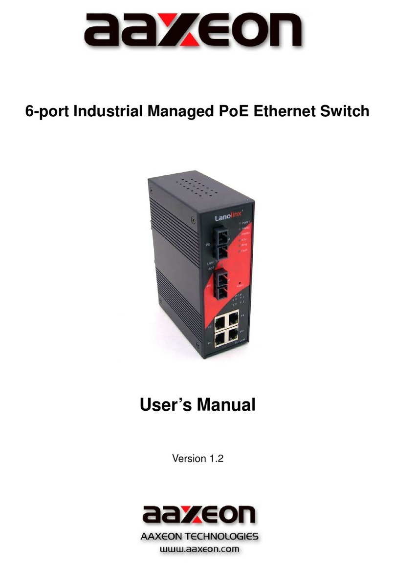
AAxeon LNX-1002NM-67-T User manual

8-port 10/100TX + 2-port 100FX IP-67
Managed Industrial Ethernet Switch
User Manual

May-2011
Content
Overview............................................................1
Introduction .............................................................. 1
Features – 8 10/100TX + 2 100FX........................... 3
Features – 8 10/100TX ............................................3
Technical Specifications – 8 10/100TX + 2 100FX ..4
Technical Specifications – 8 10/100TX....................7
Packing List............................................................ 10
Safety Precaution................................................... 10
Hardware Description.......................................11
Physical Dimensions.............................................. 11
8 10/100TX + 2 100FX....................................................11
8 10/100TX .....................................................................12
Bottom View........................................................... 13
LED Indicators........................................................ 14
8 10/100TX + 2 100FX....................................................14
8 10/100TX .....................................................................15
Installation........................................................16

Fast Ethernet Ports ................................................ 16
Wiring the Power Inputs......................................... 17
Wiring the P-Fail Alarm Contacts...........................18
Wall Mounting ........................................................ 19
Grounding the Ethernet Switch.............................. 20
Installation Steps.................................................... 21
Configuration....................................................22
RS-232 Console..................................................... 22
Pin Assignments .............................................................22
Login in the Console Interface.........................................23
SSH........................................................................ 25
Configuring PuTTY..........................................................25
Web-Based Management ......................................30
SSL.................................................................................31
System Information.........................................................33
IP Configuration ..............................................................34
DHCP Server ..................................................................37
TFTP...............................................................................41
System Event Log...........................................................44
Fault Relay Alarm............................................................50

SNTP Configuration........................................................51
IP Security.......................................................................55
User Authentication.........................................................57
N-Key Transaction ..........................................................58
Port Statistics..................................................................59
Port Control.....................................................................61
Port Trunk.......................................................................63
Port Mirroring..................................................................71
Rate Limiting...................................................................72
VLAN Configuration ........................................................73
Rapid Spanning Tree......................................................82
SNMP Configuration .......................................................86
QoS Configuration...........................................................92
X-Ring2...........................................................................95
LLDP Configuration.........................................................98
802.1X/Radius.................................................................99
MAC Address Table......................................................103
IGMP/MLD Snooping ....................................................107
Static Filtering ...............................................................108
Factory Default..............................................................109
Save Configuration........................................................110
System Reboot..............................................................111

Troubleshooting .............................................112
Appendix A—Command Sets ........................113
Command Level................................................... 113
System Commands Set.................................................114
Port Commands Set......................................................116
Trunk Commands Set ...................................................119
VLAN Commands Set...................................................120
Spanning Tree Commands Set.....................................122
QOS Commands Set ....................................................125
IGMP Commands Set ...................................................125
Mac / Filter Table Commands Set.................................126
SNMP Commands Set..................................................127
Port Mirroring Commands Set.......................................129
802.1x Commands Set..................................................130
TFTP Commands Set....................................................132
SystemLog, SMTP and Event Commands Set..............133
SNTP Commands Set...................................................134
X-ring Commands Set...................................................136

1
Overview
Introduction
To create the reliability in your network, the IP-67 Managed Industrial
Switch comes equipped with a proprietary redundant network
protocol—X-Ring II, which provides users with an easy way to establish
a redundant Ethernet network with ultra high-speed recovery time less
than 10ms. Also, the long MTBF (Mean Time Between Failures)
ensures that the industrial switch will continue to operate until a Gigabit
network infrastructure has been established without requiring any extra
upgrade costs.
Apart from eight fast Ethernet ports, the 8 10/100TX + 2 100FX IP-67
Managed Industrial Switch also comes equipped with 2 waterproof fiber
ports for both single and multi mode fiber optic cabling. The fiber slots
can be used for the application of wideband uploading and long
distance transmission to fit the field request flexibility.
Heavy Duty
Designed with circular M12 connectors for Fast Ethernet interface, the
Managed Industrial Switch provides the rugged construction which
complies with IP67 standards. Therefore, the equipment is especially
intended for the damp, dusty, and vibrant environments.
Dual Power Inputs
The redundant power input design for the IP-67 Managed Industrial
Switch gives a backup power solution. With both the power inputs
supplied, and if either one fails the other one will be activated to keep
the system operating continually. When one of the power inputs fails,
the P-Fail LED indicator lights up and send an alarm through the relay
output for notification purposes.

2
Flexible Mounting
The IP-67 Managed Industrial Switch is compact and can be mounted
on the wall, so it is suitable for any space-constrained environment.
Wide Operating Temperature
The operating temperature of the IP-67 Managed Industrial Switch is
between -40 and 75oC. With such a wide range, you can use the IP-67
Managed Industrial Switch in some of the harshest industrial
environments that exist.
Easy Troubleshooting
LED indicators make troubleshooting quick and easy. Each
10/100Base-TX port has an LED indicator displaying the link status.
Also the indicators PWR1, PWR2 and P-Fail help you diagnose the
system immediately.

3
Features – 8 10/100TX + 2 100FX
2Gbps back-plane (switching fabric)
2 x 100Base-FX waterproof LC-type single/multi mode fiber ports
X-Ring II path redundant supported
IPv6 supported
Wide-range redundant power
TFTP firmware update and system configuration restoration/backup
Supports N-Key for configuration restoration/backup (optional)
Features – 8 10/100TX
1.6Gbps back-plane (switching fabric)
X-Ring II path redundant supported
IPv6 supported
Wide-range redundant power
TFTP firmware update and system configuration restoration/backup
Supports N-Key for configuration restoration/backup (optional)

4
Technical Specifications – 8 10/100TX + 2 100FX
The technical specifications of 8 10/100TX + 2 100FX IP-67 Managed
Industrial Switch are listed as follows.
Communications
Standard IEEE 802.3, 802.3u, 802.3x, 802.3ad
IEEE 802.1d, 802.1p, 802.1Q, 802.1w, 802.1x
LAN 10/100BaseTX, 100BaseFX
Transmission Speed Up to 100 Mbps
Interface
Ethernet 8 x M12, 4-pole D-coded, female (10/100TX)
2 x 100 LC type socket with waterproof (100FX)
Console 1 x M12, 8-pole A-coded, female (RS-232)
Power Receptacle 1 x M12, 5-pole A-coded, male
Relay Alarm 1 x M12, 3-pole A-coded, female (1A @ 24 VDC)
LED Indicators System: Power1, Power2, P-Fail, R-Master
10/100BaseTX port: Link/Active
100BaseFX port: Link/Active
Management
Configuration Web browser, serial console, SNMP v1/v2c/v3,
Telnet, TFTP, N-Key (optional), IPv6, SNTP
SNMP MIB RFC 1215 Trap, RFC1213 MIBII, RFC 1157 SNMP
MIB, RFC 1493 Bridge MIB, RFC 2674 VLAN MIB,
RFC1643 , RFC 1757, RSTP MIB, LLDP MIB,
Private MIB
VLAN Port-based VLAN, IEEE 802.1Q tagged and
double-tagged VLAN, GVRP
Redundancy 802.1w/d RSTP/STP
X-Ring II (Recovery time < 10ms)
Security SSL, SSH, DHCP Server with Port-IP binding,
IP access security, user authentication, multi-user
login , 802.1X port access control

5
Traffic Control Port trunking with LACP, rate limit and storm control,
IGMP Snooping/Query for multicast group, multicast
filtering, IEEE 802.3x flow control, IEEE 802.1p QoS
Diagnostics Port mirroring, real-time traffic statistics, MAC
address table, system event log, E-mail alert,
SNMP trap, RMON, LLDP/LLDP-MED
Power
Power Consumption 8.1 watts max. @ 48 VDC
Power Input 2 x unregulated +12 ~ 48 VDC
Mechanism
Dimensions (WxHxD) 193 x 176 x 62.5 mm
Enclosure IP-67 protection, aluminum shell
Installation Wall-mount
Environment
Operating Temperature -40 ~ 75oC
Operating Humidity 5% ~ 95% (non-condensing)
Storage Temperature -40 ~ 85oC
Storage Humidity 5% ~ 95% (non-condensing)
MTBF 320420 hrs
Certifications
Safety UL 508; (suitable for use in Class I, Division 2,
Groups A, B, C, and D locations)
Railway EN50155 compliant
EMC CE, FCC Class A
CE EN61000-6-2
CE EN61000-6-4
CE EN61000-4-2 (ESD)
CE EN61000-4-3 (RS)

6
CE EN61000-4-4 (EFT)
CE EN61000-4-5 (Surge)
CE EN61000-4-6 (CS)
CE EN61000-4-8 (Magnetic Field)
Free Fall IEC60068-2-32
Shock IEC61373
Vibration IEC61373

7
Technical Specifications – 8 10/100TX
The technical specifications of 8 10/100TX IP-67 Managed Industrial Switch
are listed as follows.
Communications
Standard IEEE 802.3, 802.3u, 802.3x, 802.3ad
IEEE 802.1d, 802.1p, 802.1Q, 802.1w, 802.1x
LAN 10/100BaseTX
Transmission Speed Up to 100 Mbps
Interface
Ethernet 8 x M12, 4-pole D-coded, female (10/100TX)
Console 1 x M12, 8-pole A-coded, female (RS-232)
Power Receptacle 1 x M12, 5-pole A-coded, male
Relay Alarm 1 x M12, 3-pole A-coded, female (1A @ 24 VDC)
LED Indicators System: Power1, Power2, P-Fail, R-Master
10/100BaseTX port: Link/Active
Management
Configuration Web browser, serial console, SNMP v1/v2c/v3,
Telnet, TFTP, N-Key (optional), IPv6, SNTP
SNMP MIB RFC 1215 Trap, RFC1213 MIBII, RFC 1157 SNMP
MIB, RFC 1493 Bridge MIB, RFC 2674 VLAN MIB,
RFC1643 , RFC 1757, RSTP MIB, LLDP MIB,
Private MIB
VLAN Port-based VLAN, IEEE 802.1Q tagged and
double-tagged VLAN, GVRP
Redundancy 802.1w/d RSTP/STP
X-Ring II (Recovery time < 10ms)
Security SSL, SSH, DHCP Server with Port-IP binding,
IP access security, user authentication, multi-user
login , 802.1X port access control
Traffic Control Port trunking with LACP, rate limit and storm control,

8
IGMP Snooping/Query for multicast group, multicast
filtering, IEEE 802.3x flow control, IEEE 802.1p QoS
Diagnostics Port mirroring, real-time traffic statistics, MAC
address table, system event log, E-mail alert,
SNMP trap, RMON, LLDP/LLDP-MED
Power
Power Consumption 4.8 watts max. @ 48 VDC
Power Input 2 x unregulated +12 ~ 48 VDC
Mechanism
Dimensions (WxHxD) 193 x 176 x 62.5 mm
Enclosure IP-67 protection, aluminum shell
Installation Wall-mount
Environment
Operating Temperature -40 ~ 75oC
Operating Humidity 5% ~ 95% (non-condensing)
Storage Temperature -40 ~ 85oC
Storage Humidity 5% ~ 95% (non-condensing)
MTBF 388201 hrs
Certifications
Safety UL 508; (suitable for use in Class I, Division 2,
Groups A, B, C, and D locations)
Railway EN50155 compliant
EMC CE, FCC Class A
CE EN61000-6-2
CE EN61000-6-4
CE EN61000-4-2 (ESD)
CE EN61000-4-3 (RS)
CE EN61000-4-4 (EFT)

9
CE EN61000-4-5 (Surge)
CE EN61000-4-6 (CS)
CE EN61000-4-8 (Magnetic Field)
Free Fall IEC60068-2-32
Shock IEC61373
Vibration IEC61373

10
Packing List
1 x IP-67 Managed Industrial Switch
1 x M12 to D-sub 9 female console cable
1 x User Manual (CD-ROM)
Compare the contents of the industrial switch with the standard checklist
above. If any item is damaged or missing, please contact the local dealer
for service.
Safety Precaution
Attention
If DC voltage is supplied by an external circuit, please use a
protection device on the power supply input.

11
Hardware Description
This section is intended to introduce the industrial switch’s hardware specification, port,
cabling and wiring information.
Physical Dimensions
8 10/100TX + 2 100FX
The figure below illustrates the dimensions 193mm x 176mm x 62.5mm (W x H x D) for
the 8 10/100TX + 2 100FX IP-67 Managed Industrial Switch.
Mechanical Dimensions

12
8 10/100TX
The figure below illustrates the dimensions 193mm x 176mm x 62.5mm (W x H x D) for
the 8 10/100TX IP-67 Managed Industrial Switch.
Mechanical Dimensions

13
Bottom View
The 8 10/100TX + 2 100FX IP-67 Managed Industrial Switch, as the figure shown
below, is equipped with two LC type fiber connectors located on the bottom.
The bottom side of the 8 10/100TX + 2 100FX IP-67 Managed Industrial Switch

14
LED Indicators
8 10/100TX + 2 100FX
LED indicators located on the front panel display the power status and network status
of the 8 10/100TX + 2 100FX IP67 Managed Industrial Switch. Please refer to the
following table for further details.
LED
Color Description
PWR1 Green On Power input 1 is active
Off Power input 1 is inactive
PWR2 Green On Power input 2 is active
Off Power input 2 is inactive
P-Fail
(depends on the
Fault Relay Alarm
configuration)
Red
On Power or Ethernet port failure occurs
Off No failure occurs
R-Master Green On The industrial switch is the master of the X-ring group
Off Non-master device
P9, P10 Green
On LC fiber port is linking
Blinks Data is transmitting or receiving
Off Not connected to network
P1 ~ P8 Green
On Connected to network
Blinks Data is transmitting or receiving
Off Not connected to network
Definition of LED indicators

15
8 10/100TX
LED indicators located on the front panel display the power status and network status
of the 8 10/100TX IP67 Managed Industrial Switch. Please refer to the following table
for further details.
LED
Color Description
PWR1 Green On Power input 1 is active
Off Power input 1 is inactive
PWR2 Green On Power input 2 is active
Off Power input 2 is inactive
P-Fail
(depends on the
Fault Relay
Alarm
configuration)
Red
On Power or Ethernet port failure occurs
Off No failure occurs
R-Master Green On The industrial switch is the master of the X-ring group
Off Non-master device
P1 ~ P8 Green
On Connected to network
Blinking Data is transmitting or receiving
Off Not connected to network
Definition of LED indicators
Table of contents
Other AAxeon Switch manuals