AAxeon LNP-600N User manual

6-port Industrial Managed PoE Ethernet Switch
User’s Manual
Version 1.2

Aaxeon Technologies, LLC
1
Table of Content
Getting to Know Your Switch........................................................................3
1.1 About the LNP-600N/LNP-602N Managed Industrial Switch................................... 3
1.2 Software Features.................................................................................................... 3
1.3 Hardware Features................................................................................................... 3
Hardware Installation.....................................................................................4
2.1 Installing Switch on DIN-Rail.................................................................................... 4
2.1.1 Mount LNP-600N/LNP-602N Series on DIN-Rail ................................................ 4
2.2 Wall Mounting Installation ........................................................................................ 5
2.2.1 Mount LNP-600N/LNP-602N Series on wall........................................................ 5
Hardware Overview........................................................................................7
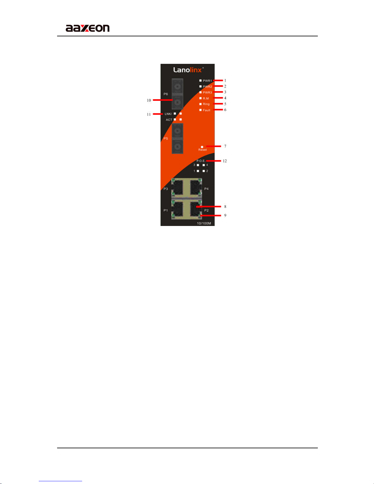
3.1 Front Panel............................................................................................................... 7
3.2 Front Panel LEDs................................................................................................... 10
3.3 Bottom Panel.......................................................................................................... 10
3.4 Rear Panel ..............................................................................................................11
Cables...........................................................................................................12
4.1 Ethernet Cables...................................................................................................... 12
4.1.1 100BASE-TX/10BASE-T Pin Assignments........................................................ 12
4.2 Fibers ..................................................................................................................... 13
WEB Management........................................................................................14
5.1 Configuration by Web Browser .............................................................................. 14
5.1.1 About Web-based Management........................................................................ 14
5.1.2 Basic Setting...................................................................................................... 16
5.1.2.1 Switch setting ............................................................................................ 16
5.1.2.2 Admin Password ....................................................................................... 16
5.1.2.3 IP configuration ......................................................................................... 17
5.1.2.4 SNTP Configuration .................................................................................. 18
5.1.2.5 Backup & Restore ..................................................................................... 21
5.1.2.6 Upgrade Firmware..................................................................................... 21
5.1.2.7 Factory Default.......................................................................................... 22
5.1.2.8 System Reboot.......................................................................................... 22
5.1.3 Port Configuration.............................................................................................. 23

Aaxeon Technologies, LLC
2
5.1.3.1 Port Control............................................................................................... 23
5.1.3.2 Port Status................................................................................................. 23
5.1.4 Redundancy....................................................................................................... 24
5.1.4.1 Fast Recovery Mode................................................................................. 24
5.1.4.2 Redundant Ring ........................................................................................ 24
5.1.4.3 RSTP......................................................................................................... 26
5.1.5 SNMP Configuration .......................................................................................... 28
5.1.5.1 SNMP – Agent Setting.................................................................................... 28
5.1.5.2 SNMP –Trap Setting ................................................................................. 29
5.1.6 VLAN.................................................................................................................. 30
5.1.6.1 VLAN Configuration – Port Based............................................................. 30
5.1.7 Warning.............................................................................................................. 31
5.1.7.1 Fault Alarm ................................................................................................ 31
5.1.8 Front Panel ........................................................................................................ 36
5.1.9 Save Configuration ............................................................................................ 36
5.1.10 LLDP.............................................................................................................. 37
5.1.11 Power over Ethernet (P.O.E.)........................................................................ 37
5.1.12 Auto-Ping Check............................................................................................ 39
5.1.13 Schedule........................................................................................................ 40
Technical Specifications .............................................................................41

LNP600N / LNP-602N User’s Manual
Aaxeon Technologies, LLC
3
Getting to Know Your Switch
1.1 About the LNP-600N/LNP-602N Managed Industrial
Switch
The LNP-600N/LNP-602N switch is a cost-effective and powerful industrial switch with many
features. These switches can work under wide temperature and dusty environment and
humid condition.The LNP-600N/LNP-602N support Power over Ethernet, a system to
transmit electrical power with data to remote devices over standard twisted-pair cable. The
LNP-600N/LNP-602N switch has 4 X 10/100TX PSE (Power Sourcing Equipment) ports
which are fully compliant with IEEE 802.3af standard.
1.2 Software Features
World’s fastest Redundant Ethernet Ring (Recovery time < 10ms over 250 units
connection)
Supports Ring Coupling, Dual Homing and RSTP over Redundant Ring
Support fast recovery mode
Easy web configuration
1.3 Hardware Features
Wide Operating Temperature: -40 to 75oC
Storage Temperature: -40 to 85 oC
Operating Humidity: 5% to 95%, non-condensing
4 10/100Base-T(X) Ethernet port with PSE provides up to 25 watts
10/100Base-T(X) Ethernet port
100Base-FX Fiber port

LNP600N / LNP-602N User’s Manual
Aaxeon Technologies, LLC
4
Hardware Installation
2.1 Installing Switch on DIN-Rail
Each switch has a DIN-Rail kit on rear panel. The DIN-Rail kit helps switch to fix on the
DIN-Rail. It is easy to install the switch on the DIN-Rail:
2.1.1 Mount LNP-600N/LNP-602N Series on DIN-Rail
Step 1: Slant the switch and mount the metal spring to DIN-Rail.
Step 2: Push the switch toward the DIN-Rail until you heard a “click” sound.
Metal Spring

LNP600N / LNP-602N User’s Manual
Aaxeon Technologies, LLC
5
2.2 Wall Mounting Installation
Each switch has another installation method for users to fix the switch. A wall mount panel
can be found in the package. The following steps show how to mount the switch on the
wall:
2.2.1 Mount LNP-600N/LNP-602N Series on wall
Step 1: Remove DIN-Rail kit.
Step 2: Use 6 screws that can be found in the package to combine the wall mount panel.
Just like the picture shows below:

LNP600N / LNP-602N User’s Manual
Aaxeon Technologies, LLC
6
The screws specification shows in the following two pictures. In order to prevent switches
from any damage, the screws should not be larger than the size that is used in the switch.
Pozidrive
Step 3: Mount the combined switch on the wall.

LNP600N / LNP-602N User’s Manual
Aaxeon Technologies, LLC
7
Hardware Overview
3.1 Front Panel
The following table describes the labels that stick on the LNP-600N/LNP-602N.
Port Description
10/100 RJ-45 fast
Ethernet ports
10/100Base-T(X) RJ-45 fast Ethernet ports support
auto-negotiation.
Default Setting :
Speed: auto
Duplex: auto
Flow control : disable
Fiber port 100BaseFX
P.O.E. Port Port 1 ~ 4 contain PSE function compliant with IEEE802.3af
P.O.E. specifications.
ResetPush reset button 2 to 3 seconds to reset the switch.
Push reset button 5 second to reset the switch into Factory
Default.

LNP600N / LNP-602N User’s Manual
Aaxeon Technologies, LLC
8
LNP-600N
1. LED for PWR1. When the PWR1 links, the green led will be light on.
2. LED for PWR2. When the PWR2 links, the green led will be light on.
3. LED for PWR3. When the PWR3 links, the green led will be light on.
4. LED for R.M. (Ring master). When the LED light on, it means that the switch is the ring
master of Redundant Ring.
5. LED for Ring. When the led light on, it means the Redundant Ring is activated.
6. LED for Fault Relay. When the fault occurs, the amber LED will be light on.
7. Reset button. Push the button 3 seconds for reset; 5 seconds for factory default.
8. 10/100Base-T(X) Ethernet ports.
9. LED for Ethernet ports status.
10. 10/100Base-T(X) Ethernet ports.
11. LED for Ethernet ports status.
12. LED for P.O.E. power supplied.

LNP600N / LNP-602N User’s Manual
Aaxeon Technologies, LLC
9
LNP-602N
1. LED for PWR1. When the PWR1 links, the green led will be light on.
2. LED for PWR2. When the PWR2 links, the green led will be light on.
3. LED for PWR3. When the PWR3 links, the green led will be light on.
4. LED for R.M. (Ring master). When the LED light on, it means that the switch is the ring
master of Redundant Ring.
5. LED for Ring. When the led light on, it means the Redundant Ring is activated.
6. LED for Fault Relay. When the fault occurs, the amber LED will be light on.
7. Reset button. Push the button 3 seconds for reset; 5 seconds for factory default.
8. 10/100Base-T(X) Ethernet ports.
9. LED for Ethernet ports status.
10. 100BaseFX fiber port.
11. LNK/ACT LED for fiber port.
12. LED for P.O.E. power supplied.

LNP600N / LNP-602N User’s Manual
Aaxeon Technologies, LLC
10
3.2 Front Panel LEDs
LED Color Status Description
PWR1 Green On DC power module 1 activated.
PWR2 Green On DC power module 2 activated.
PWR3 Green On Power jack activated.
R.M Green On Ring Master.
Ring Green
On Ring enabled.
Slowly blinking Ring topology has problem
Fast blinking Ring work normally.
Fault Amber On Fault relay. Power failure or Port
down/fail.
10/100Base-T(X) Fast Ethernet ports
LNK / ACT Green On Port link up.
Blinking Data transmitted.
Full Duplex Amber On Port works under full duplex.
P.O.E. Green On P.O.E. activated
100Base-FX Fiber ports
ACT Green Blinking Data transmitted.
LNK Amber On Port link up.
3.3 Bottom Panel
The bottom panel components of LNP-600N/LNP-602N are showed as below:
1. Terminal block includes: PWR1, PWR2 (+48V DC) and Relay output (1A@24VDC).
2. Power jack for PWR3 (+48VDC).
.
LNP-600N/LNP-602N power connection

LNP600N / LNP-602N User’s Manual
Aaxeon Technologies, LLC
11
3.4 Rear Panel
The rear panel components of LNP-600N/LNP-602N are showed as below:
1. Screw holes for wall mount kit.
2. Din-Rail kit

LNP600N / LNP-602N User’s Manual
Aaxeon Technologies, LLC
12
Cables
4.1 Ethernet Cables
The LNP-600N/LNP-602N switches have standard Ethernet ports. According to the link
type, the switches use CAT 3, 4, 5,5e UTP cables to connect to any other network device
(PCs, servers, switches, routers, or hubs). Please refer to the following table for cable
specifications.
Cable Types and Specifications
Cable Type Max. Length Connector
10BASE-T Cat. 3, 4, 5 100-ohm UTP 100 m (328 ft) RJ-45
100BASE-TX Cat. 5 100-ohm UTP UTP 100 m (328 ft) RJ-45
4.1.1 100BASE-TX/10BASE-T Pin Assignments
With 100BASE-TX/10BASE-T cable, pins 1 and 2 are used for transmitting data, and pins
3 and 6 are used for receiving data.
RJ-45 Pin Assignments
Pin Number Assignment
1 TD+
2 TD-
3 RD+
4 P.O.E. power input +
5 P.O.E. power input +
6 RD-
7 P.O.E. power input -
8 P.O.E. power input -
The LNP-600N/LNP-602N switches support auto MDI/MDI-X operation. You can use a
straight-through cable to connect PC and switch. The following table below shows the
10BASE-T/ 100BASE-TX MDI and MDI-X port pin outs.

LNP600N / LNP-602N User’s Manual
Aaxeon Technologies, LLC
13
MDI/MDI-X pins assignment
Pin Number MDI port MDI-X port
1 TD+(transmit) RD+(receive)
2 TD-(transmit) RD-(receive)
3 RD+(receive) TD+(transmit)
4 P.O.E. power input + P.O.E. power input +
5 P.O.E. power input + P.O.E. power input +
6 RD-(receive) TD-(transmit)
7 P.O.E. power input - P.O.E. power input -
8 P.O.E. power input - P.O.E. power input -
Note: “+” and “-” signs represent the polarity of the wires that make up each wire pair.
4.2 Fibers
The following two models, LNP-602N-MM, LNP-602N-SS30, have fiber optical ports. The
fiber optical ports are in multi-mode (0 to 2 km, 1310 nm in 50/125 µm, 62.5/125 µm) and
single-mode (9/125 µm) with SC connector. Please remember that the TX port of Switch A
should be connected to the RX port of Switch B.
Switch A
TX RX
RX TX
Switch B
Fiber cord

LNP600N / LNP-602N User’s Manual
Aaxeon Technologies, LLC
14
WEB Management
5.1 Configuration by Web Browser
This section introduces the configuration by Web browser.
5.1.1 About Web-based Management
An embedded HTML web site resides in flash memory on the CPU board. It contains
advanced management features and allows you to manage the switch from anywhere on
the network through a standard web browser such as Microsoft Internet Explorer.
The Web-Based Management function supports Internet Explorer 5.0 or later. It is based
on Java Applets with an aim to reduce network bandwidth consumption, enhance access
speed and present an easy viewing screen.
Note: By default, IE5.0 or later version does not allow Java Applets to open sockets. You need to explicitly
modify the browser setting in order to enable Java Applets to use network ports.
Preparing for Web Management
The default value is as below:
IPAddress: 192.168.10.1
Subnet Mask: 255.255.255.0
Default Gateway: 192.168.10.254
User Name: admin
Password: admin
System Login
1. Launch the Internet Explorer.
2. Type http:// and the IP address of the switch. Press “Enter”.

LNP600N / LNP-602N User’s Manual
Aaxeon Technologies, LLC
15
3. The login screen appears.
4. Key in the username and password. The default username and password is
“admin”.
5. Click “Enter” or “OK” button, then the main interface of the Web-based management
appears.
Login screen
Main Interface
Main interface

LNP600N / LNP-602N User’s Manual
Aaxeon Technologies, LLC
16
5.1.2 Basic Setting
5.1.2.1 Switch setting
Switch setting interface
The following table describes the labels in this screen.
Label Description
System Name Assign the name of switch. The maximum length is 64 bytes
System Description Display the description of switch.
System Location Assign the switch physical location. The maximum length is 64
bytes
System Contact Enter the name of contact person or organization
Firmware Version Display the switch’s firmware version
Kernel Version Display the kernel software version
MAC Address Display the unique hardware address assigned by manufacturer
(default)
5.1.2.2 Admin Password
Change web management login username and password for the management security
issue

LNP600N / LNP-602N User’s Manual
Aaxeon Technologies, LLC
17
Admin Password interface
The following table describes the labels in this screen.
Label Description
User name Key in the new username (The default is “admin”)
New Password Key in the new password (The default is “admin”)
Confirm password Re-type the new password.
Apply Click “Apply” to activate the configurations.
5.1.2.3 IP configuration
You can configure the IP Settings and DHCP client function through IP configuration.
IP Configuration interface
The following table describes the labels in this screen.
Label Description
DHCP Client To enable or disable the DHCP client function. When DHCP

LNP600N / LNP-602N User’s Manual
Aaxeon Technologies, LLC
18
client function is enabling, the switch will assign the IP address
from the network DHCP server. The default IP address will be
replaced by the IP address which the DHCP server has assigned.
After clicking “Apply” button, a popup dialog will show up to
inform you when the DHCP client is enabling. The current IP will
lose and you should find the new IP on the DHCP server.
IP Address Assign the IP address that the network is using. If DHCP client
function is enabling, you do not need to assign the IP address.
The network DHCP server will assign the IP address for the
switch and it will be displayed in this column. The default IP is
192.168.10.1
Subnet Mask Assign the subnet mask for the IP address. If DHCP client
function is enabling, you do not need to assign the subnet mask.
Gateway Assign the network gateway for the switch. The default gateway
is 192.168.10.254
DNS1 Assign the primary DNS IP address
DNS2 Assign the secondary DNS IP address
Apply Click “Apply” to activate the configurations.
5.1.2.4 SNTP Configuration
The SNTP (Simple Network Time Protocol) settings allow you to synchronize switch
clocks in the Internet.
SNTP Configuration interface

LNP600N / LNP-602N User’s Manual
Aaxeon Technologies, LLC
19
The following table describes the labels in this screen.
Label Description
SNTP Client Enable or disable SNTP function to get the time from the SNTP
server.
Daylight Saving Time Enable or disable daylight saving time function. When daylight
saving time is enabling, you need to configure the daylight saving
time period.
UTC Time zone Set the switch location time zone. The following table lists the
different location time zone for your reference.
Local Time Zone Conversion from UTC
Time at 12:00 UTC
November Time Zone - 1 hour 11 am
Oscar Time Zone -2 hours 10 am
ADT - Atlantic Daylight -3 hours 9 am
AST - Atlantic Standard
EDT - Eastern Daylight -4 hours 8 am
EST - Eastern Standard
CDT - Central Daylight -5 hours 7 am
CST - Central Standard
MDT - Mountain Daylight -6 hours 6 am
MST - Mountain Standard
PDT - Pacific Daylight -7 hours 5 am
PST - Pacific Standard
ADT - Alaskan Daylight -8 hours 4 am
ALA - Alaskan Standard -9 hours 3 am
HAW - Hawaiian Standard -10 hours 2 am
Nome, Alaska -11 hours 1 am
This manual suits for next models
1
Table of contents
Other AAxeon Switch manuals