AB Quality ALLEN-BRADLEY 1391-DES User manual

User Manual
1391-DES Digital
AC Servo Drive

Important User Information Because of the variety of uses for this equipment and because of the
differences between this solid-state equipment and electromechanical
equipment, the user of and those responsible for applying this equipment
must satisfy themselves as to the acceptability of each application and use
of the equipment. In no event will Allen-Bradley Company be responsible
or liable for indirect or consequential damages resulting from the use or
application of this equipment.
The illustrations shown in this manual are intended solely to illustrate the
text of this manual. Because of the many variables and requirements
associated with any particular installation, the Allen-Bradley Company
cannot assume responsibility or liability for actual use based upon the
illustrative uses and applications.
No patent liability is assumed by Allen-Bradley Company with respect to
use of information, circuits or equipment described in this text.
Reproduction of the content of this manual, in whole or in part, without
written permission of the Allen-Bradley Company is prohibited.
This information in this manual is organized in numbered chapters. Read
each chapter in sequence and perform procedures when you are instructed
to do so. Do not proceed to the next chapter until you have completed all
procedures.
!ATTENTION: Identifies information about practices or
circumstances that can lead to personal injury or death, property
damage or economic loss.
Attentions help you:
•identify a hazard
•avoid the hazard
•recognize the consequences
IMPORTANT: Identifies information that is especially important for
successful application and understanding of the product.

Summary of Changes
1-4
Summary of Changes
Summary of Manual Changes This release of the 1391-DES User Manual contains some new and updated
information. The new and updated information is summarized in the table
below. For further information, refer to the page numbers provided.
Description of New or Updated Information Page Type
Linear Accel/Decel information added 1-4 New
Speed Regulation specification added 2-1 New
Torque Plus Motor, Gearbox & Cable info 3-4, 7, 8 New
Important statement added to TB1 5-1 New
Bus voltage info added to shunt resistor 5-4 New
Important statement added 5-7 Clarification
Parameter 69 name change 6-14 Update
Parameter 170 maximum value updated 6-18 Update
Parameter 199 updated 6-20 Update
Encoder Wiring 7-5 Clarification
Torque Plus info added to step 11 8-3 New
Torque Plus info added (steps 30, 31) 8-7 New
Figure 8.1 updated 8-10 Update
Linear Accel/Decel information added 8-11 New
Torque Plus data added 9-3 New
#4 added to Auto Tune Fault 11-7 Update
TP50 description updated 11-10 Update
Enclosure items list A-3 New
Interconnect drawings updated & added App. B Update

Chapter
1-5
Introduction
Manual Objectives This manual is meant to guide the interface, installation, programming and
troubleshooting of a 1391-DES Digital AC Servo Drive. The contents are
arranged in order from a general description of the drive to troubleshooting
and maintenance. To assure successful installation and operation, the
material presented must be thoroughly read and understood before
proceeding. Particular attention must be directed to the Attention and
Important statements contained within.
Important Information about this Manual
This manual has been prepared primarily to support this product in a single
drive application. It is a standard document that is intended to help the user
understand the individual operating characteristics and limitations of this
equipment including hazards associated with installation, programming and
maintenance procedures. Note the following points:
•This equipment has been designed to meet the requirements of a
component drive in an integrated drive system.
•While the potential hazards associated with the drive remain the same
when used in a system environment, it must be noted that special
considerations are to be given to characteristics of other peripheral
solid-state control equipment and the cumulative impact on safety.
•Manufacturers and engineering groups responsible for specification or
design of electrical control equipment must refer to applicable industry
standards and codes for specific safety guidelines and interface
requirements.
•In the actual factory environment, the user is responsible to ensure
compliance with applicable machine and operator safety codes or
regulations which are beyond the scope and purpose of this document.

Chapter 1
Introduction
1-6
General Precautions In addition to the precautions listed throughout this manual, the following
statements which are general to the drive must be read and understood.
ATTENTION: Only personnel familiar with the 1391-DES
Digital Servo Drive and associated machinery should plan or
implement the installation, start-up and subsequent maintenance
of the drive. Failure to comply may result in personal injury
and/or equipment damage.
ATTENTION: An incorrectly applied or installed drive can
result in component damage or a reduction in product life.
Wiring or application errors, such as, undersizing the motor,
incorrect or inadequate AC supply, or excessive ambient
temperatures may result in malfunction of the drive.
ATTENTION: This drive contains ESD (Electrostatic
Discharge) sensitive parts and assemblies. Static control
precautions are required when installing, testing, servicing or
repairing this assembly. Component damage may result if ESD
control procedures are not followed. If you are not familiar with
static control procedures, reference Allen-Bradley publication
8000-4.5.2, Guarding Against Electrostatic Damage or any
other applicable ESD Protection Handbook.
!
!
!
Certification Notice: In order to maintain UL listing on Allen-Bradley
1391-DES Digital Servo Drives, the user must provide power from a 1391
Isolation Transformer. Use of any other transformer voids the UL listing.
The user is responsible for providing motor overload protection in
accordance with the National Electrical Code (NEC), and any other local
codes that may apply.
Drive Description The 1391-DES Pulse Width Modulated Digital Servo Drive is a digital and
programmable single axis, AC servo drive. It has been packaged to require
a minimum amount of panel space while containing, as standard, a number
of features required by the machine tool and automated equipment
industries.
The 1391-DES allows Allen-Bradley 1326 AC servomotors to be operated
from 33% to 50% over their rated speed. This can help achieve greater
precision, a finer finished product and increased production from existing
machinery.

Chapter 1
Introduction
1-7
The 1391-DES is generally used with computer aided, closed loop
positioning systems such as Allen-Bradley “S” Class or IMC products.
These systems control the position and linear or rotary motion of various
machine members on an automated machine. To enhance system reliability,
the 1391-DES has an encoder output (AQB) that produces four channels of
2048, 1024, 512 or 256 lines and two marker pulses per motor revolution
which feeds position information to the position controller.
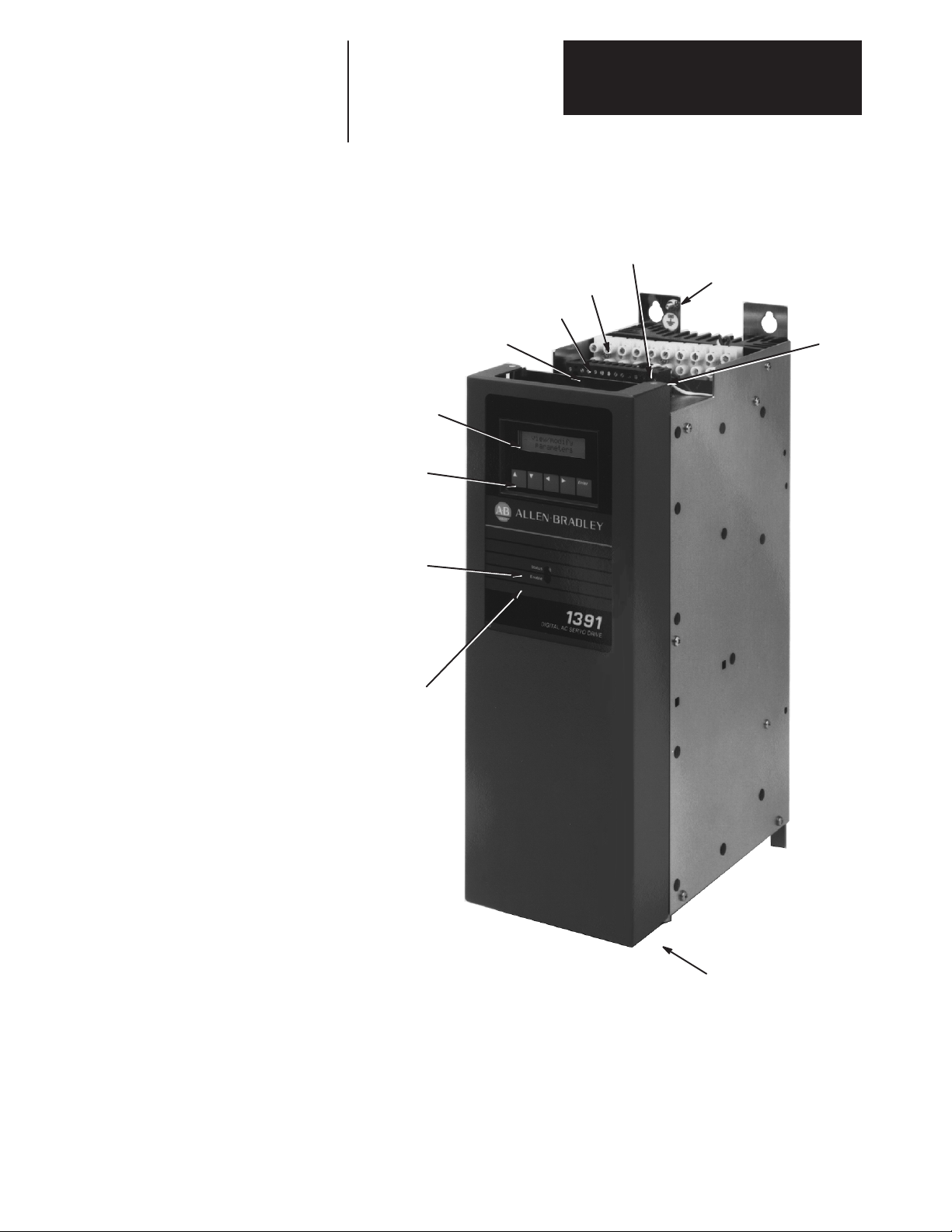
All components are mounted in an open framed package with a slide-on
front cover. The drive is intended to be panel mounted in an enclosure and
ventilated with filtered and/or cooled air. An internal fan is included to
circulate air over the power heat sink.
The 1391-DES converts a three-phase, 50/60 Hz input, to a variable AC
voltage with controlled phase, amplitude and frequency. The output which
is proportional to a user supplied analog command, regulates the speed
and/or current (torque) of a 1326 permanent magnet AC servomotor. The
drive is available in ratings of 15, 22.5 and 45A RMS with all package
sizes being identical. A 1391 Transformer, 1326 AC Servomotor and 1326
Cables complete the servo system.
Standard Features The 1391-DES contains a number of standard features required in a typical
automated machine servo system.
•Input protected against transient voltage.
•A power line/DB contactor which opens the AC line to the drive and
inserts a shunt regulator resistor across the DC bus whenever the
contactor is de-energized.
•An integral circuit breaker which will open all three AC line leads in the
event of a short circuit condition in the power circuitry.
•A standard 300V DC power bus supply that includes an integral shunt
regulator.
•A shunt regulator resistor to dissipate the energy generated by the motor
during regenerative braking.
•Prompted startup procedure to shorten setup time.
•Two line LCD display and programming panel.
•Patented current control implementation.
•Torque feedforward differential input.
•Microprocessor based logic boards that can be quickly removed and
easily interchanged for troubleshooting and diagnostics.
•Three drive ratings that are in the same physical package and have
identical mounting dimensions.
•True vector control.
•Up to 600 feet (183 meters) between drive and motor.

Chapter 1
Introduction
1-8
Options/Modifications The 1391-DES contains most functions needed in a servo system.
The following are selectable at the user’s option:
•Contactor Auxiliary Switch
Two N.O. (normally open) contacts are mounted on the main power
contactor and wired to the power terminal block. These contacts can be
used in a motor brake control circuit or as an indicator that the contactor
has closed.
•Current or Torque Amplifier Operation
When the velocity loop is being closed as part of the position control
system, the drive can be configured to operate as a current or torque
amplifier by selection on the programming panel.
•External Shunt Regulator Resistor
On 15 and 22.5A drives an internal power resistor that is part of the DC
bus voltage shunt regulator can dissipate 162 watts continuous power.
Some applications such as an overhauling load have excessive
regenerative energy to dissipate. For these applications, an external
shunt regulator resistor rated at 386 watts continuous can be supplied for
user mounting on 22.5A drives. This is selectable by removing the
jumper on TB5 and using an external resistor. The shunt has integral
fusing accessible from the outside of 15 and 22.5A drives. The 45A
drive has an externally mounted resistor and fuse.
Important: An external shunt regulator resistor is included as standard
equipment on 45A units. An additional unit is not required.
•Tach Output
A voltage equal to 1.2V DC/1000 RPM is available at TB2.
•Torque or Current Monitor
A voltage equal to 3.0V DC=100% scaled current is available at TB2.
•Anti-Backlash
Anti-backlash control can be implemented with several software
parameters and an additional instruction manual. Contact your local
Allen-Bradley Sales Office for details.
•Linear Accel/Decel
Linear accel/decel can be set using the CR-APG-001 Control Module.
This module provides a manually generated trapezoidal velocity profile
for up to four preset speeds.
Important: The 1391-DES contains one accel/decel rate which can be
used if accel/decel times will be the same.
Drive Layout Figure 1.1 provides an exterior view of the 1391-DES AC Servo Drive,
showing accessibility of various components.

Chapter 1
Introduction
1-9
Figure 1.1
1391-DES Digital AC Servo Drive
TB2 – Interface Signals
TB3 – A Quad B Encoder Output Signals
Ground Stud
TB5 – Power Connections
TB4 – Control Signals
Circuit Breaker Fuses
2 Line, 16 Character
LCD Display
5 Button Keypad used
for Programming
Duty Cycle Selector Switch
Status LED
- Flashes green when no faults are
present and the bus is low.
- Steady green when no faults are
present and bus voltage is OK.
- Flashes red when a fault has
occurred.
Enable LED
- Steady green when Enable input is
closed at TB2-9 & 10.
- Not illuminated when Enable input
is open.

Chapter 1
Introduction
1-10
End of Chapter

Chapter
2-1
Specifications
Chapter Objectives Chapter two contains the electrical and environmental specifications for the
1391-DES. Dimensions are provided in Appendix A.
Drive Specifications The general specifications of the 1391-DES are provided in the listing
below. The specifications are divided when necessary for the various drive
ratings.
Specific Drive Ratings 1391-DES15 1391-DES22 1391-DES45
Nominal Bus Voltage 300V DC 300V DC 300V DC
Continuous Current (RMS) 15A 22.5A 45A
Peak Current (RMS) 30A 45A 90A
Continuous Power Output 5.0 kW 7.5 kW 15.0 kW
Peak Power Output 10.0 kW 15.0 kW 30.0 kW
Input Circuit Breaker Rating 17A RMS 26A RMS 38A RMS
Circuit Breaker Interrupt Rating
(Symmetrical Amperes) 1300A 1300A 1300A
Unit Weight in lbs. (kg) 22 (9.97) 28 (12.69) 34 (15.40)
All Drive Ratings
Static Gain (A/RMS) 1.5 x Rated Motor Current / rpm (typical)
Form Factor 1.03 or less
Peak Current Limit Adjust 20 to 300% of Rated Motor Current or 2 x Continuous Rating of
Drive (max.), whichever achieves Drive Peak Current Rating first
Drive Efficiency 85% (Minimum at Rated Load)
Power Factor 95% Minimum
Modulation Frequency 2500 Hz ±10%
Drift (Referred to Tach) 0.07 rpm /Degrees C. Maximum
Speed Regulation 0 to 0.05% of Maximum Motor Speed with 95% Load Change
Ambient Temperature 0 to 60°C (32 to 140°F)
Storage Temperature 0 to 65°C (32 to 149°F)
Input Voltage (from Transformer) Power: 230V AC +10%/–15%, Three-Phase, 50/60 Hz ±3 Hz
Control: 36V AC, Single-Phase
Transformer Input Tolerance +10%, –15%
Relative Humidity 5 to 95% Non-Condensing
Deadband Zero
Altitude 1000 meters (3300 feet)
Integral Fan Output 50 CFM (Unloaded)
Max. RMS Short Circuit Current 1300A (Symmetrical Amperes)
Certifications UL Listed - File No. E59272, CSA Certified - File No. LR32334-548,
Specifications are for reference only and are subject to change without notice.

Chapter 2
Specifications
2-2
Environmental Specifications The 1391-DES must be mounted in an enclosure that is clean, dry and
ventilated by filtered or cooled air. Enclosures vented with ambient air
must have appropriate filtering to protect against contamination caused by
oils, coolants, dust, condensation etc. The ambient air temperature must be
kept between 0 to 60°C (32 to 140°F) and the humidity between 5 and
95%, non-condensing.
The 1391-DES is equipped with an integral cooling fan. The general flow
of air through the unit must be maintained by following the recommended
spacing guidelines found in Chapter 7. The 1391-DES can operate at
elevations to 3300 feet (1000 meters) without derating, however, the
current rating must be derated by 3% for each additional 1000 feet (305
meters) up to 10,000 feet (3050 meters). Consult with your local
Allen-Bradley Sales Representative prior to operation over 10,000 feet
(3050 meters).
Drive Power Dissipation The 1391-DES dissipation characteristics are approximated in Table 2.A.
Table 2.A
Drive Power Dissipation
Rated Power Output
(%)
20
40
60
80
100
1391-DES15
(watts)
38
76
114
152
190
1391-DES22
(watts)
55
110
165
220
275
1391-DES45
(watts)
104
208
312
416
520
Transformer Power Dissipation The power dissipation characteristics of the 1391 Isolation Transformer are
shown in Table 2.B.
Table 2.B
1391 Isolation Transformer Power Dissipation
Rated Power Output
(%)
20
40
60
80
100
1.5kVA
(watts)
13
25
38
50
60
3.5kVA
(watts)
35
70
105
140
175
5.0kVA
(watts)
50
100
150
200
250
10.0kVA
(watts)
100
200
300
400
500
12.5kVA
(watts)
125
250
375
500
625
15.0kVA
(watts)
150
300
450
600
750
Important: Power Dissipation figures shown are for use in calculating
cumulative system heat dissipation to ensure ambient temperature inside
enclosure does not exceed 60°C (140°F).

Chapter
3-1
Receiving, Unpacking and Inspection
Chapter Objectives Chapter 3 provides the information needed to unpack, properly inspect and
if necessary, store the 1391-DES and related equipment. The section
entitled Inspection provides a complete explanation of the 1391-DES
catalog numbering system.
Receiving It is the responsibility of the user to thoroughly inspect the equipment
before accepting the shipment from the freight company. Check the item(s)
received against the purchase order. If any items are obviously damaged, it
is the responsibility of the user not to accept delivery until the freight agent
has noted the damage on the freight bill. Should any concealed damage be
found during unpacking, it is again the responsibility of the user to notify
the freight agent. The shipping container must be left intact and the freight
agent should be requested to make a visual inspection of the equipment.
Unpacking Remove all packing material, wedges, or braces from within and around
the drive. Remove all packing material from the cooling fans, heat sink etc.
Important: Before the installation and start-up of the drive, a general
inspection of mechanical integrity (i.e. loose parts, wires, connections,
packing materials, etc.) must be made.
Inspection After unpacking, check the item(s) nameplate catalog number against the
purchase order. An explanation of the catalog numbering system is
included on the following pages as an aid for nameplate interpretation.
Storing The drive should remain in its shipping container prior to installation. If the
equipment is not to be used for a period of time, it must be stored
according to the following instructions:
•Store in a clean, dry location.
•Store within an ambient temperature range of 0 to 65°C (32 to 149°F).
•Store within a relative humidity range of 5% to 95%, non-condensing.
•Do not store equipment where it could be exposed to a corrosive
atmosphere.
•Do not store equipment in a construction area.

Chapter 3
Receiving, Unpacking and Inspection
3-2
Isolation Transformer
1391 T
First Position Second Position Third Position
Bulletin
Number Type
015
Fourth Position
kVA Rating
D
Fifth Position
Primary Voltage
& Frequency
T
Secondary
Voltage
–
Description
240/480V AC, Three-
Phase, 60 Hz
240/380/415/480V AC,
Three-Phase, 50/60 Hz
208/230/460/575V AC,
Three-Phase, 60 Hz
Letter
D
E
N
kVA
1.5
3.5
5.0
10.0
12.5
15.0
Number
015
035
050
100
125
150
Description
Transformer
Open Core
and Coil
Letter
T
Description
230V AC, three-phase
and four 36V AC,
single-phase
C.T.windings
Letter
T
1391
Bulletin
Number Accessory
Module
TA2–
Description
Fits all kVA ratings on 1386, 1388,
1389 and 1391 Isolation Transformers.
Letter
TA2
NEMA Type 1 Transformer Enclosure Kit
External Shunt Regulator Resistor
1391 MOD SR22A
First Position Second Position Third Position
Bulletin
Number Type Description
–
Code
SR22A
SR45A
Description
Shunt Regulator Resistor for 22.5A Drive
Shunt Regulator Resistor for 45A Drive 1
Description
Modifica-
tion Kit
Code
MOD
–
1Drive comes equipped with this resistor as standard. Catalog number is provided if spare or replacement is required,

Chapter 3
Receiving, Unpacking and Inspection
3-3
Bulletin 1391-DES Drive
1391 DES15
First Position Second Position
Bulletin
Number User
Interface
Description
Includes Integral
Display
Third Position
Code
DI
DI
Fifth Position
Options
A––
Configuration/
Current Rating
Description
15A Continuous Current
22.5A Continuous Current
45A Continuous Current
Code
DES15
DES22
DES45
Description
24V DC M contactor
coil voltage instead of
115V AC (available
on 22A drives only)
115V AC M contactor
coil voltage
Letter
A
Blank
–
Fourth Position
Output
Configuration
AQB–
Description
Encoder Output –
2048, 1024, 512,
256 selectable
pulses/motor
revolution
Code
AQB
1326 A 3
First Position Second Position Third Position
Bulletin
Number
Fourth Position
Max. Op.
Speed 2
E
Fifth Position
Series
11
Standard
Options
–
Description
AC
Servomotor
PM Type
Letter
A
Design Motor
Length
Description
72 lb.-in. (8.1 N-m) Holding Brake w/90V DC Coil.
120 lb.-in. (13.6 N-m) Holding Brake w/90V DC Coil.
360 lb.-in. (40.7 N-m) Holding Brake w/90V DC Coil.
72 lb.-in. (8.1 N-m) Holding Brake w/24V DC Coil.
120 lb.-in. (13.6 N-m) Holding Brake w/24V DC Coil.
360 lb.-in. (40.7 N-m) Holding Brake w/24V DC Coil.
Code
A4
A5
A7
K4
K5
K7
Sixth Position
–BA
Type
Description
Factory
use only
Eighth Posi-
tion
–
1326AB Servomotor
Description
Sequentially
lettered to
designate frame
diameters.
Description
Sequentially
numbered to
indicate stack
length within a
given frame size.
A4
Mounting & Shaft
Description
Description
4.25” (108 mm)
5.88” (149 mm)
7.63” (194 mm)
Code
A
B
C
RPM
1600/2000
2000/3000
3000/4000
5000/6000
Letter
B
C
E
G
Seventh Posi-
tion
Description
NEMA Inch Combina-
tion Face/Flange with
Keyway
IEC Metric Flange
with Keyway
Code
11
21
2Ratings shown indicate the rated speed and speed capability of the motor with the 1391-DES (rated/w 1391-DES).

Chapter 3
Receiving, Unpacking and Inspection
3-4
Code
A4
A5
A7
K4
K5
K7
1326AB MOD
First Position Second Position Third Position
Bulletin
Number
Fourth Position
Motor
Mounting3
A
Fifth Position
Material
1–
Description
Modifica-
tion Kit
Code
MOD
Shaft
Seal Motor
Series
Sixth Position
SS V
Type
–
Shaft Oil Seal Kit
Description
Viton
Letter
V
Letter
A
B
C
Description
Std. Inch
Metric
Number
1
2
–
Brake Power Supply Rectifier
1326 MOD BPS
Bulletin
Number Type Description
–
Code
BPS
Description
Single-phase, full-wave, screw mount
rectifier. 115V AC input, for use with 90V DC
brakes.4
Description
Modifica-
tion Kit
Code
MOD
–
3“A” Series motors with brake must use 1326AB-MOD-SSV-A2.
4Up to 4 brakes per rectifier can be used.
1326 AB 30
First Position Second Position Third Position
Bulletin
Number
Fourth Position
Max. Operating
Speed
E
Fifth Position
Series
21
Standard
Options
–
Description
Ferrite AC
Servomo-
tor
Letter
AB
Voltage Motor
Length
Description
72 lb.-in. (8.1 N-m) Holding Brake w/90V DC Coil for 1326AB-A4
120 lb.-in. (13.6 N-m) Holding Brake w/90V DC Coil for 1326AB-A5
360 lb.-in. (40.7 N-m) Holding Brake w/90V DC Coil for 1326AB-A7
72 lb.-in. (8.1 N-m) Holding Brake w/24V DC Coil for 1326AB-A4
120 lb.-in. (13.6 N-m) Holding Brake w/24V DC Coil for 1326AB-A5
360 lb.-in. (40.7 N-m) Holding Brake w/24V DC Coil for 1326AB-A7
Sixth Position
–A4
Type
Eighth Position
–
1326AB Torque Plus Series Servomotor
Description
Sequentially
lettered to
designate frame
diameters.
Description
Sequentially
numbered to
indicate stack
length within a
given frame size.
A4
Mounting & Shaft
Description
Description
115 mm
166 mm
215 mm
Code
4
5
7
Rated/1391-DES
1600/2000 rpm
2000/3000 rpm
3000/4000 rpm
5000/6000 rpm
Letter
B
C
E
G
Seventh Position
Description
IEC Metric
Flange with
Keyway
Code
21
Rating
230V AC
Code
A
Standard
Series A
Series B
Series C
Torque Plus
-A4
-A5
-A7
Use
Metric
Only

Chapter 3
Receiving, Unpacking and Inspection
3-5
1326AB MOD
First Position Second Position Third Position
Bulletin
Number
Fourth Position
Coupling Size
for . . .
–
Description
Modifica-
tion Kit
Code
MOD
Mounting Adapter
Kit for . . .
M4 C1
Type
–
Feedback Mounting Adapter Kit6
MotorSeries
A, B, C (A4, A5, A7 Torque Plus)
For M22, M23, M24, M25, M26
Code
C1
Blank
–
Motor Junction Box Kit 5
1326AB MOD RJAB
First Position Second Position Third Position
Bulletin
Number Type Description
–
Code
RJAB
RJB
C
Description
For all AB-A & B Series Motors
(A4 & A5 Torque Plus Motors)
For all AB-B4 & Cx Series Motors
(A7 Torque Plus Motors)
Description
A-B 845H/T Encoder for AB-A series motor (A4 Torque Plus)
A-B 845H/T Encoder for AB-B series motor (A5 Torque Plus)
A-B 845H/T Encoder for AB-C series motor (A7 Torque Plus)
Type VC/VD 4.25” (108 mm) Resolver for AB-B series motor (A5 Torque Plus)
Type VC/VD 4.25” (108 mm) Resolver for AB-C series motor (A7 Torque Plus)
0.375” (9.5 mm) diameter heavy duty shaft extension adapter
0.625” (15.9 mm) diameter heavy duty shaft extension for type VC/VD 4.25”
(108 mm) resolver
Foot mounting kit for M25
Code
M4
M5
M6
M22
M23
M24
M25
M26
Description
Modifica-
tion Kit
Code
MOD
–
5The motor comes standard with IP65 plug style connectors mounted radially to the motor. This kit allows the
connectors to be brought out axially to the motor without further wiring. Kit includes Motor Junction Box and
MountingHardware.
6All kits contain a feedback device mounting adapter and mounting hardware. M4, M5 and M6 include a
motor to encoder coupling. M22 and M23 do not include a coupling since it is included with the resolver
feedbackdevice.

Chapter 3
Receiving, Unpacking and Inspection
3-6
Code
1:1
1:2
1:2.5
1:5
255
256
424
425
800
801
Feedback Coupling 7
1326 MOD C1
First Position Second Position Third Position
Bulletin
Number Type Coupling
Size
–
Description
Modifica-
tion Kit
Code
MOD
Code
C1
C2
Size–Motor Shaft to Encoder Shaft
3/8” to 3/8” (9.5 mm to 9.5 mm) –
Standard on all 1326AB Motors
1/4” to 3/8” (6.4 mm to 9.5 mm)
–
7The feedback coupling is included as standard with all Feedback Mounting Adapter Kits.
8Kit includes Resolver Feedback Package, mounting hardware and 3/8” to 3/8” (9.5 mm to 9.5 mm) resolver to motor mounting coupling.
1326AB MOD
First Position Second Position Third Position
Bulletin
Number Gear Ratio
Input:Resolver
–
Description
Modifica-
tion Kit 8
Code
MOD
VC
Type
Resolver Feedback Package
–
Description
Single device format – 1 turn of the motor shaft to 1 turn of the resolver.
Single device format – 1 turn of the motor shaft to 2 turns of the resolver.
Single device format – 1 turn of the motor shaft to 2.5 turns of the resolver.
Single device format – 1 turn of the motor shaft to 5 turns of the resolver.
Absolute master/vernier format – 1:1 input/master, 255:256 master/vernier
for IMC 120, 121, 123 only.
Absolute master/vernier format – 1:1 input/master, 256:255 master/vernier
for 8600 series and MAX, IMC S class controls with a REC 4096 Board.
Absolute master/vernier format – 1:1 input/master, 424:425 master/vernier
for IMC 120, 121, 123 only.
Absolute master/vernier format – 1:1 input/master, 425:424 master/vernier
for 8600 series and MAX, IMC S class controls with a REC 4096 Board.
Absolute master/vernier format – 1:1 input/master, 800:801 master/vernier
for IMC 120, 121, 123 only.
Absolute master/vernier format – 1:1 input/master, 801:800 master/vernier
for 8600 series controllers (is not applicable for use with MAX and IMC S
Class controls)
1:1
Fourth Position
Resolver Feedback
Package
Code
VC
VD
Description
4.25” (108 mm) feedback package with cast
housing and single or vernier (dual) format with
receiver (Harowe 11BRW-300-F-58A or equivalent)
type resolver(s) for use with A-B series 8200 CNC
and IMC]120, 121, 123.
4.25” (108 mm) feedback package with cast
housing and single or vernier (dual) format with
transmitter (Harowe 11BRCX-300-C10/6 or
equivalent) type resolver(s) for use with A-B series
8600, MAX and IMC S Class controllers with a
REC 4096 Board.

Chapter 3
Receiving, Unpacking and Inspection
3-7
Blower Mod Kit
1326AB MOD G3
First Position Second Position Third Position
Bulletin
Number Type Description
–
Description
Modifica-
tion Kit
Code
MOD
Code
G3
G4
MotorSeries
Rear mounted blower for C
series motors
“Saddle” type blower for C
series motors with rear
mounted encoders
–
1326 C
First Position Second Position Third Position
Bulletin
Number
Sixth Position
Cable
Length
–
Function
PAB
Type
Power and Feedback Cables
Description
Power Connection
Letter
P
15
Fourth Position
Motor Size
Used On
Code
K
15
30
50
100
1509
2009
2509
3009
Description
Connector Kit
(No Cable)
15’ (4.6 m)
30’ (9.1 m)
50’ (15.2 m)
100’ (30.4 m)
150’ (45.7 m)
200’ (61 m)
250’ (76.2 m)
300’ (91.4 m)
Commutation &
Feedback Connection
845H/T Encoder
All 4.25” (108 mm)
Resolver Packages
F
E
V
Description
Connector
& Cable
Assembly
Connector
on both
ends (for
use with
1391C-HB)
Code
C
CC
Type
Series A & B (except
1326AB-B4)
Series C & 1326AB-B4
Code
AB
C
All SeriesU
T
Fifth Position
Power Track
Cable
Description
All Series,
used for
high flex
applications
Standard
Cable
Letter
T
Blank
Description
Standard
Cable
Extended
length cable
used with
1391B-ES
&
1391-DES
Only
Code
1326
1326ES9
9The extended length option is only available for 1326-CFUxx, CPABxx and CPCxx cables and can only be used with 1391B-ES and 1391-DES drives.

Chapter 3
Receiving, Unpacking and Inspection
3-8
Type
Code
03
05
10
15
20
30
50
100
–
Description
3:1
5:1
10:1
15:1
20:1
30:1
50:1
100:1
1326AB PG
First Position Second Position Third Position
Bulletin
Number Gear Ratio
(Motor Shaft:Output Shaft)
–A05
Fourth Position
Used on 1326AB
Motor Series
Code
A
B
C
Standard
Series A
Series B
Series C
Planetary Gearbox
LB 21–
Code
PG
RP
Description
Straight
Planetary Gearbox
Right Angle
Planetary Gearbox
Options
Code
Blank
LB
Description
No Options
Low Back-
lash Option
Fifth Position
Adapter
Code
21
11
Description
Metric
English
Sixth Position
Torque Plus
-A4 10
-A5 10
-A7 10
10 Use only -21 (Metric) style adapter gearboxes for -A4, -A5 Torque Plus Motors.

Table of Contents
i
Introduction Chapter 1
Manual Objectives 1-1. . . . . . . . . . . . . . . . . . . . . . . . . . . . . . . . . . . . . . . . .
General Precautions 1-2. . . . . . . . . . . . . . . . . . . . . . . . . . . . . . . . . . . . . . . .
Drive Description 1-2. . . . . . . . . . . . . . . . . . . . . . . . . . . . . . . . . . . . . . . . . .
Standard Features 1-3. . . . . . . . . . . . . . . . . . . . . . . . . . . . . . . . . . . . . . . . . .
Options/Modifications 1-4. . . . . . . . . . . . . . . . . . . . . . . . . . . . . . . . . . . . . .
Drive Layout 1-4. . . . . . . . . . . . . . . . . . . . . . . . . . . . . . . . . . . . . . . . . . . . .
Specifications Chapter 2
Chapter Objectives 2-1. . . . . . . . . . . . . . . . . . . . . . . . . . . . . . . . . . . . . . . . .
Drive Specifications 2-1. . . . . . . . . . . . . . . . . . . . . . . . . . . . . . . . . . . . . . . .
Environmental Specifications 2-2. . . . . . . . . . . . . . . . . . . . . . . . . . . . . . . .
Drive Power Dissipation 2-2. . . . . . . . . . . . . . . . . . . . . . . . . . . . . . . . . . . .
Transformer Power Dissipation 2-2. . . . . . . . . . . . . . . . . . . . . . . . . . . . . . .
Receiving, Unpacking & Inspection Chapter 3
Chapter Objectives 3-1. . . . . . . . . . . . . . . . . . . . . . . . . . . . . . . . . . . . . . . . .
Receiving 3-1. . . . . . . . . . . . . . . . . . . . . . . . . . . . . . . . . . . . . . . . . . . . . . . .
Unpacking 3-1. . . . . . . . . . . . . . . . . . . . . . . . . . . . . . . . . . . . . . . . . . . . . . .
Inspection 3-1. . . . . . . . . . . . . . . . . . . . . . . . . . . . . . . . . . . . . . . . . . . . . . . .
Storing 3-1. . . . . . . . . . . . . . . . . . . . . . . . . . . . . . . . . . . . . . . . . . . . . . . . . .
Description of Operation Chapter 4
Chapter Objectives 4-1. . . . . . . . . . . . . . . . . . . . . . . . . . . . . . . . . . . . . . . . .
General 4-1. . . . . . . . . . . . . . . . . . . . . . . . . . . . . . . . . . . . . . . . . . . . . . . . . .
300V DC Power Bus Supply 4-1. . . . . . . . . . . . . . . . . . . . . . . . . . . . . . . . .
PWM Operation 4-1. . . . . . . . . . . . . . . . . . . . . . . . . . . . . . . . . . . . . . . . . . .
Shunt Regulator Operation 4-3. . . . . . . . . . . . . . . . . . . . . . . . . . . . . . . . . .
Logic Power Supply 4-3. . . . . . . . . . . . . . . . . . . . . . . . . . . . . . . . . . . . . . .
Logic Control Boards 4-3. . . . . . . . . . . . . . . . . . . . . . . . . . . . . . . . . . . . . .
Fault Monitoring and Detection 4-3. . . . . . . . . . . . . . . . . . . . . . . . . . . . . . .
Microprocessor Control 4-5. . . . . . . . . . . . . . . . . . . . . . . . . . . . . . . . . . . . .
Isolated Current Sensing 4-5. . . . . . . . . . . . . . . . . . . . . . . . . . . . . . . . . . . .
Integral Circuit Breaker 4-5. . . . . . . . . . . . . . . . . . . . . . . . . . . . . . . . . . . . .
Line/DB Contactor 4-5. . . . . . . . . . . . . . . . . . . . . . . . . . . . . . . . . . . . . . . . .
Power Driver Board 4-5. . . . . . . . . . . . . . . . . . . . . . . . . . . . . . . . . . . . . . . .
A Quad B Board 4-5. . . . . . . . . . . . . . . . . . . . . . . . . . . . . . . . . . . . . . . . . .
Starting and Stopping 4-5. . . . . . . . . . . . . . . . . . . . . . . . . . . . . . . . . . . . . .
Power-Up/Down Sequence 4-7. . . . . . . . . . . . . . . . . . . . . . . . . . . . . . . . . .
Inputs, Outputs and Switch SettingsChapter 5
Chapter Objectives 5-1. . . . . . . . . . . . . . . . . . . . . . . . . . . . . . . . . . . . . . . . .
Inputs/Outputs 5-1. . . . . . . . . . . . . . . . . . . . . . . . . . . . . . . . . . . . . . . . . . . .
Switch Settings 5-6. . . . . . . . . . . . . . . . . . . . . . . . . . . . . . . . . . . . . . . . . . .
This manual suits for next models
1
Popular Servo Drive manuals by other brands

YASKAWA
YASKAWA Sigma-V Series user manual

Rockwell Automation
Rockwell Automation Allen-Bradley Kinetix TLP Series installation instructions

Metronix
Metronix DIS-2 310/2 FB FS STO product manual

Omron
Omron 1S Series Startup guide

Danfoss
Danfoss 176F6491 installation instructions

Festo
Festo CMMT-ST-C8-1C-...-S0 Series Original instructions

LS Mecapion
LS Mecapion L7 Series user manual

Allen-Bradley
Allen-Bradley 2097-V31PR0 installation instructions

ANCA Motion
ANCA Motion D2 Series user guide

Rockwell Automation
Rockwell Automation Allen-Brandley Kinetix 3 Original instructions

IMI
IMI MC15/24-C Mounting instructions

Kollmorgen
Kollmorgen AKD Fault Card