ab Solares Smart Spa User manual

SolaresTM Smart Spa Parts Manual
CD0039 2 Rev:1121
For Assistance Contact:
Apollo Corporation
450 Main St
Somerset, WI 54025
+1 (715) 247-5625
Fax +1 (715) 247-3424
https://apollobath.com
The information in this manual is subject to change without notice.
In no event will Apollo Corporation be liable for technical or editorial omissions made herein; nor for direct,
special, incidental, or consequential damages resulting from the furnishing, performance, or use of this
material.
This manual is copyrighted with all rights reserved. Under the copyright laws, this manual may not be copied, in
whole or part, without the written consent of Apollo Corporation.

SolaresTM Smart Spa Parts Manual
CD0039 3 Rev:1121
Contents
Dashboard.....................................................................................................................................................4
Rails and Jets.................................................................................................................................................5
Drain..............................................................................................................................................................7
Whirlpool Pump............................................................................................................................................8
Manifold........................................................................................................................................................9
Side Panel Trim Removal ............................................................................................................................12
Rada Valve...................................................................................................................................................13
Docking Components..................................................................................................................................16
RemedyTM....................................................................................................................................................18
Remedy-Ballast and Fuse........................................................................................................................21
Power Hub ..................................................................................................................................................23
Power Hub –Fuses and Relays ...............................................................................................................24
Power Hub –Power Supply and Stepper Driver .....................................................................................26
HMI..............................................................................................................................................................28
Tilt Switch....................................................................................................................................................29
Door ............................................................................................................................................................30
Door Components...................................................................................................................................31
Secure Glide Transfer System .....................................................................................................................33
Chair Assembly-Front..............................................................................................................................34
Chair Assembly-Back...............................................................................................................................35
Carrier Base Assembly.............................................................................................................................37
Preventative Maintenance Schedule..........................................................................................................39
Errors...........................................................................................................................................................41

SolaresTM Smart Spa Parts Manual
CD0039 4 Rev:1121
Dashboard
Item
Part #
Description
Item
Part #
Description
1
320006
Shower Wand
3
200450
Skin Care Hose Assembly;
Shampoo
2
340541
Commercial Soap Dispenser
4
200451
Skin Care Hose Assembly; Oil
Replacement Instructions
Part #2 –Commercial Soap Dispenser
1. Use screwdriver to disengage cable clamp from hose and remove hose.
2. Remove nut and washer from underside of pump.
3. Remove old pump and install new one.
4. Replace washer and nut on underside of tub.
5. Slide hose over tube and replace clamp.
Part #3/4 –Skin Care Hose Assembly; Shampoo/ Oil
1. Unscrew end of hose from jug of product and set on cardboard.
2. Pump out as much as shampoo/ oil as possible to clear access from line.
3. Use screwdriver to disengage cable clamp from hose.
4. Remove hose and install new line.
5. Replace cable clamp onto new hose.
6. Insert opposite end of hose assembly into matching product bottle and thread cap until secured
to bottle.

SolaresTM Smart Spa Parts Manual
CD0039 5 Rev:1121
Rails and Jets
Item
Part #
Description
Item
Part #
Description
1
350704
Soc Cap Screw; 3/8-16 x 3.0
6
330302
Momentary Switch; Push
Button
2
350703
Soc Cap Screw; 3/8-16 x 2.5
7
401041
LH Tub Transfer Beam
3
320549
TRX Jet Dir Internal; BN
8
340538
Gasket; 3/8 ID x 1 OD x 1/4
4
401040
RH Tub Transfer Beam
9
350512
3/8 Star Washer; SS
5
320572
94GPM Suction Cover; BN
10
350077
3/8-16 Thread Hex Nut

SolaresTM Smart Spa Parts Manual
CD0039 6 Rev:1121
Replacement Instructions
Part # 3 –TRX Jet
1. Rotate jet counterclockwise until it stops rotating.
2. Force jet to continue rotating counterclockwise until it pops out of the body.
3. Place new jet in place and apply pressure while rotating clockwise until jet snaps into place.
Part # 4/7 –LH/RH Transfer Beam
1. Remove screws and pull rail off of tub.
2. Place Gasket (Item 8) into matching holes on the back side of the new rail.
3. Carefully place rail on tub ensuring none of the gaskets fall out of place.
4. Replace screws through rail and tub shell.
5. Apply anti-seize to screws and replace star washer and nut to end of screw.
6. Tighten until snug.
Part # 5 –94GPM Suction Cover; BN
1. Remove screw from center of suction cover.
2. Remove old suction cover.
3. Place new suction cover with edge of part ensuring tab on backside of part lines up with the
notch in the top of the fitting. Note: it is critical that the section of the cover without any holes is
facing up as to ensure optimal drainage.
4. Replace screw in center of part.
Part # 6 –Momentary Switch; Push Button
1. Remove right side panel and right-side panel trim.
2. Switch off tub power using power switch on electrical box or unplug tub from wall. Warning!
Failure to do so could result in electric shock!
3. Use small chancel locks or pliers to remove nut on underside of switch.
4. Pull button up and out of tub to expose contacts on the bottom.
5. Use screwdriver to loosen screws and remove wires from switch.
6. Attach wires to terminals of new switch and tighten down screws ensuring there are no loose
strands. Which wire goes to which terminal isn’t important, they just need to go in separate
terminals and have no jumpers between them.
7. Drop switch back into tub and replace nut.
8. Tighten nut until switch is secure.
9. Power on unit and verify correct operation of button in input section of maintenance screen per
operations manual. Screen should indicate switch is “HIGH” when pushed in and “LOW” when
released. resecure connections if this is not the case.
10. Replace side panel trim and side panels.

SolaresTM Smart Spa Parts Manual
CD0039 7 Rev:1121
Drain
Item
Part #
Description
Item
Part #
Description
1
320577
3” Dia Slide Valve; 12VDC
2
500354
Slide Valve Drain Seal Kit; 3in
Replacement Instructions *Note: These instructions also apply for Rapid Fill Slide Valve.
1. Loosen hose clamp from Fernco coupler attaching rear side of drain assembly and remove drain
hose. This will make it easier to handle the assembly.
2. Remove screws from new assembly
3. Remove PVC fittings and gaskets from valve.
4. Disconnect cable from old assembly on tub.
5. Remove screws and remove valve from plumbing.
6. Discard old gaskets and valve.
7. Apply new gaskets to PVC fittings on either side of old assembly. (large ID side of gasket fits over
ridge of fitting.)
8. Place the new valve between the two halves of the old assembly and push parts together as
shown above. (Valve handle should face side of tub with skin and spa care products with the
valve pointed above tub frame.)
9. Use hardware from new assembly to reassemble valve.
10. Reattach hose through Fernco coupler and tighten down fitting.
11. Connect drain to cable previously removed from old drain.

SolaresTM Smart Spa Parts Manual
CD0039 8 Rev:1121
Whirlpool Pump
Item
Part #
Description
Item
Part #
Description
1
330281
Whirlpool Pump; 7 Amp
5
350705
5/16 flat washer
2
350053
5/16-18 Hex Bolt x 1.5; SS
6
350621
5/16 Lock Washer
3
350706
Hex Bolt; 3/16-18 x 3.5
7
350054
5/16-18 Coarse Thread Nut
4
350121
3/16 Flat Washer; SS
8
400072
Motor Mount Washer;
Rubber
Replacement Instructions
1. Unplug the pump from the electrical box.
2. Loosen the set screw securing the ground to the pump.
3. Disconnect the ground wire from the pump.
4. Disconnect the unions from the top and side of the pump.
5. Loosen the hose clamp securing the check valve to the top port of the pump and slide it off.
6. Remove the three bolts mounting the pump in place and set the pump aside.
7. Install the new pump on the frame using the hardware as shown above. Note: The long bolt
secures the highest foot of the pump.
8. Reattach the unions to the side and top of the pump.
9. Assemble the check valve onto the top port of the pump and secure the hose clamp to seal it.
10. Push the ground wire into the pump’s ground fitting and secure it using the set screw in the
assembly.
11. Plug the pump into the short Nema 15 cable coming out of the large electrical enclosure.

SolaresTM Smart Spa Parts Manual
CD0039 9 Rev:1121
Manifold
Item
Part #
Description
Item
Part #
Description
1
200448
Fresh Water Manifold Ass.
7
330380
Series 35KR; 2-way-2pos val.
2
320566
Chemical Injector; 3/8 MPT
8
330381
Series 3685 2-way, 2pos val.
3
320589
Injector Metering Tip; Red
9
320596
Backflow W/ Air Vent; ¾ NPT
4
320728
PH Mach. screw; 8-32 x 2 1/4
10
200442
Spa Care Hose Assembly;
Cleaner
5
350696
#8 Start Washer
11
200443
SPA Care Hose Assembly;
Disinfectant
6
330300
NTC Thermistor; 10Kohm
Replacement Instructions
Part #1 –Fresh Water Manifold Assembly
1. Turn off hot/ cold water supply.
2. Use touch screen to briefly open shower or fill valve to blead the water pressure from the
system.
3. Disconnect all DIN cables from the valves by loosening the screw at the back of the connector all
the way and pulling the connector off of the valve.

SolaresTM Smart Spa Parts Manual
CD0039 10 Rev:1121
4. Disconnect union at top of manifold by placing one wrench on the bottom of the union and
another on the nut.
5. Disconnect White PVC line from dual check valve assembly by loosening hose clamp and
removing tube.
6. Disconnect fill hose, shower hose, and reservoir hose (if applicable.)
7. Disconnect Cleaner & disinfectant lines.
8. Disconnect part #6.
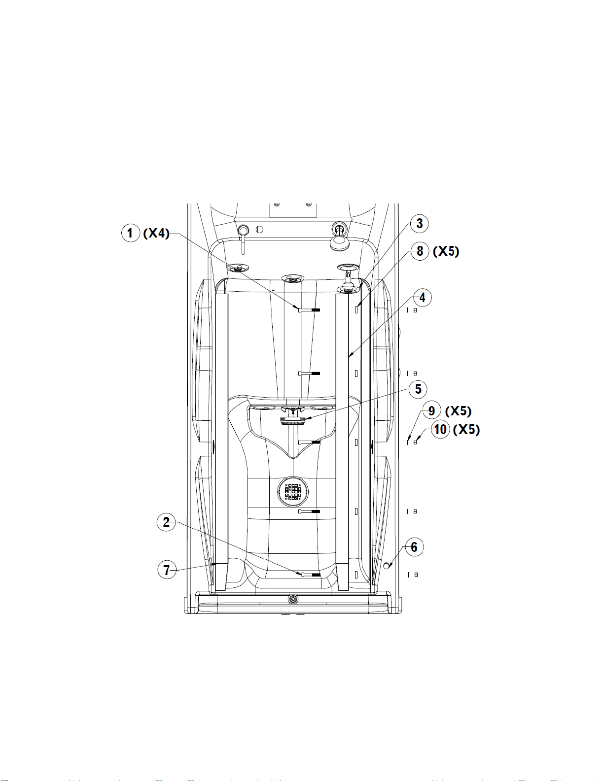
9. Remove part #4 (X4) using Philips head screwdriver and remove manifold from frame.
10. Remove union from top of old manifold and install it into new manifold. 3 wraps of thread tape
with coating of PTFE thread sealant on top is recommended for most reliable seal.
11. Install new manifold onto plate using part #4 and part #5 as shown.
12. Reinstall all hoses and connections removed in previous steps.
13. Turn water back on and use touch screen to verify all valves connected properly and that there
aren’t any leaks.
Part #2 –Chemical Injector; 3/8 MPT; Plastic
1. Remove cleaner/ disinfectant hose from injector tip.
2. Use small flat head screwdriver to pry separate teeth of hose clamps adjacent to injector & pull
hose off barb. Note: If you have ½” Vinyl tubing available it is often easier to carefully cut along
the length of the tubing to remove it from the barbs and simply replace it as it can be stubborn.
3. Twist injector counterclockwise to remove from street elbow.
4. Remove barb & metering tip from old injector and install on new injector.
5. Install new injector into street elbow.
6. Replace hose over injector barb and reinstall hose clamps.
7. Replace cleaner/ disinfectant hose.
Part #6 –NTC Thermistor; 10Kohm
1. Disconnect thermistor from cable.
2. Unthread thermistor from manifold.
3. Remove M8 connector from thermistor and install it on the new thermistor per WI0107.
4. Thread new thermistor into manifold using thread tape to seal.
5. Connect M8 connector.
6. Clear thermometer error through hitting the “Reset Error” button under maintenance or by
cycling the tub’s power.
7. Calibrate thermistor per instructions in Solares Operation manual.
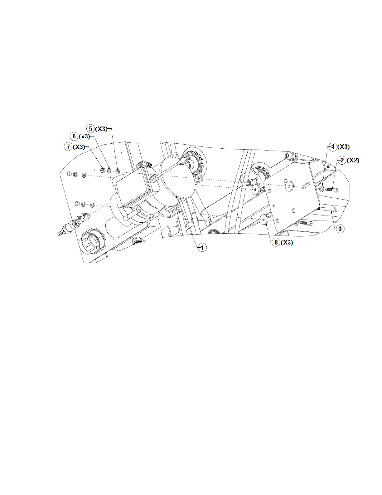
Part #7 - Series 35KR; 2-way-2pos valve
1. Disconnect DIN cable by loosening screw on back of connector all the way and pulling connector
away from valve.
2. Turn off hot/ cold water supply.
3. Use touch screen to open tub or shower valve to bleed pressure from lines.
4. Use Philips screwdriver to remove all 4 screws securing valve to manifold.

SolaresTM Smart Spa Parts Manual
CD0039 11 Rev:1121
5. Remove valve and replace with new one in same orientation as the original by ling up the short
pipe on the bottom of the valve with the hole in the manifold. (Side of valve with round base
faces center of manifold.)
6. Replace screws and the DIN connector.
7. Test valve and verify there are no leaks.
Part #8 - Series 3685 2-way, 2pos valve.
1. Disconnect DIN cable by loosening screw on back of connector all the way and pulling connector
away from valve.
2. Turn off hot/ cold water supply.
3. Use touch screen to briefly open tub or shower valve to bleed pressure form lines.
4. Remove manifold from frame per freshwater manifold replacement instructions. (Note: Valve
can be replaced without removing the manifold from the frame; however, it’s difficult to align
both the gasket and the valve together properly with the manifold while fighting gravity and
trying to keep the spring from falling out. It’s also very easy to accidently cross thread the
screws when trying to install the valve vertically. This is why it’s best to remove the manifold
before attempting a replacement of this valve.)
5. Use 9/64 hex wrench to remove all screws securing valve.
6. Remove valve and rubber seal underneath it from manifold.
7. Place rubber seal from new valve in the impression on the manifold with the large stainless
plate facing up. Carefully push edges of gasket into the impression. It’s very important that the
gasket lines up with the impression exactly.
8. Place the spring on top of the nub coming out of the center of the stainless plate.
9. Place the valve on top making sure that the side of the valve with the bump on its face is
pointing downward.
10. Lightly twist the valve back and forth with slight/ increasing pressure until the valve seats
securely onto the gasket. If everything is aligned, then the valve shouldn’t be able to rotate
freely.
11. Replace screws to secure valve to manifold. Tighten screws down lightly following a crisscrossing
star pattern like you would when securing a wheel on a car.
12. Once screws are lightly fastened; go around once more to snug up each screw following the
same pattern.
13. Replace DIN connector onto valve and turn water back on.
14. Press “Fill Tub” on water control screen to test valve for proper operation and ensure that
there’s no leaks.
Part # 9 - Backflow W/ Air Vent; ¾ NPT
1. Turn off hot/ cold water supply.
2. Use touch screen to briefly open tub or shower valve to bleed pressure form lines.
3. Use flathead screwdriver to separate teeth on hose clamp and remove it.
4. Remove vinyl hose from port on side of backflow preventer.
5. Use two wrenches to disconnect unions on top and bottom of valve without disturbing the joint
on the other side.

SolaresTM Smart Spa Parts Manual
CD0039 12 Rev:1121
6. Remove the valve and replace it with the new one ensuring there is a gasket on either side of
the valve.
7. Alight the valve with the other half of the adjacent unions and then tighten them good and snug
with two wrenches ensuring adjacent joints aren’t disturbed.
8. Reattach vinyl hose to barb on side of valve and replace hose clamp.
9. Turn on water supply and verify there are no leaks.
Side Panel Trim Removal
1. Ensure tub is raised up to highest position.
2. Remove side panel by opening access panels and removing thumb screw located towards back
side of cutout.
3. Remove screws securing lower part of frame (Detail B) and let front of frame rotate downward.
4. Remove screws shown in detail A while supporting frame.
5. Pull frame down and out to remove from tub.
6. When ready to reinstall start by tucking front of trim into front edge of tub.
7. Slide trim up until top edge of trim is recessed behind tub shell.
8. Align rear slots of frame with threaded inserts in the back of the frame as seen in detail A and
loosely install the screws.
9. Lift the front edge of the frame up until the slots line up with the holes located towards the
front of the frame as shown in detail B.
10. Lightly thread in screws.
11. Adjust frame in or out so that lines up well with the tub shell and secure all the screws.

SolaresTM Smart Spa Parts Manual
CD0039 13 Rev:1121
Rada Valve
Item
Part #
Description
Item
Part #
Description
1
200466
Mixing Valve Assembly
5
330286
Inductive Proximity Sensor;
1.5mm
2
510071
Rada Cartridge; Rada222
6
330285
Nema 17 Stepper Motor
3
350762
Carriage Bolt; 8-32 X 3/4
7
350508
Machine Screw 6-32 x 3/8; SS
4
350438
8-32 Coarse Thread Nylock
Nut
8
350725
PH Mach Screw; M3-0.5 x
8mm
Replacement Instructions
Part #1 –Mixing Valve Assembly
1. Remove side panels and side panel trim.
2. Turn off hot/ cold water supply.
3. Use touch screen to briefly open tub or shower valve to bleed pressure form lines.
4. Remove fill hoses from both elbows of Rada Valve.

SolaresTM Smart Spa Parts Manual
CD0039 14 Rev:1121
5. Disconnect M8 cable from part #5.
6. Disconnect M12 cable from part # 6.
7. Use two wrenches to disconnect union on the bottom of the assembly.
8. Loosen nuts (part #4).
9. Lift Rada assembly up to slide it out of frame.
10. Remove nuts (part #4) all the way.
11. Assemble nuts and screws (part #3 & 4) loosely onto new manifold.
12. Position Rada assembly above frame and slowly lower it so that carriage bolts make their way
into the slots.
13. Verify that the backflow preventer’s gasket is still in place and connect the union. Be sure to use
two wrenches when tightening to prevent loosening of the adjacent fitting.
14. Tighten nuts (part #4) until valve is adequately secure.
15. Connect M8 & M12 cables to parts #5 and #6 respectively.
16. Connect fill hoses to Rada assembly ensuring that the cold line is attached to the right and the
hot line to the left.
17. Verify correct assembly of the valve by running the tub fill for a while and verifying that it is able
to reach and maintain the temperature shown on the screen.
18. Replace side panel trim and side panels.
Part #2 –Radatherm Cartridge; Rada 222
1. Turn off hot/ cold water supply.
2. Loosen set screw on underside of large pulley using 2mm allen wrench.
3. Loosen 4mm screw on other side of pully using 2.5mm allen wrench.
4. Lift large pulley off of valve. You may need to loosen the screws on the top of the adjacent plate
to create some play.
5. Remove screw fastening down brass adjustment knob.
6. Remove both white clips from Rada assembly.
7. Remove black cap and brass adjustment knob.
8. Twist off top piece of brass assembly.
9. Pull Rada out of brass assembly. (It may help to briefly open one of the valves a bit to allow the
water pressure to push out the valve.)
10. Remove new valve from its packaging and apply included silicone lubricant to the gaskets.
11. Insert the new valve into the assembly ensuring that the side marked with a large H is aligned
with the left side of the assembly.
12. Thread the top brass assembly back onto the valve.
13. Turn water supply back on.
14. Go to the maintenance screen on the tub per the operations manual and push “Max Temp”
button. Water should start to enter the tub. Note: The following process will be easier if you
have a second person available to read off the water temperature for you as you won’t be able
to see it while adjusting the valve.
15. Adjust the grey knob on the Rada clockwise until the water temperature drops to the
neighborhood of 100°f.
16. Turn grey knob counterclockwise until temperature is 105°f (If you can’t get 105°f at the tub
then adjust it just beyond the point you reach the highest temperature you can.)

SolaresTM Smart Spa Parts Manual
CD0039 15 Rev:1121
17. Assemble the white adjustment stop onto the cartridge so that the stop hits the left side of the
black standoffs.
18. Line up the brass knob with the inside shape of the white stop and insert it. Avoid turning the
Rada knob any more than necessary while doing this.
19. Watch the water temperature for a good 15-20 seconds to make sure the temperature doesn’t
go above 105°f.
20. Once the valve is set you can hit the “max water temp” button again to turn off the water.
21. Place the black cap on top of the Rada valve and hold it just far enough away to prevent the
teeth from interlocking.
22. Rotate the cap clockwise until you hit a stop.
23. Push the black cap in to interlock the teeth and replace the two white clips you removed earlier.
The nubs should be positioned toward the opposite clip to secure them in place.
24. Place the screw you removed earlier into the brass adjustment knob and tighten it down.
25. Place the large pulley back on the brass knob ensuring you get the timing belt on both pulleys as
you go.
26. If you loosened the adjacent plate earlier then you’ll need to pull that plate away from the Rada
until the time belt is good and tight. With force still applied to the plate tighten the two screws
down on its back side to secure it into that position.
27. Turn the large pulley counterclockwise just past the point in which the inductive sensor’s light
(part #5) turns on.
28. Use 2mm hex wrench to tighten set screw good in snug to lock pulley in position.
29. Verify that pulley rotates clockwise without a problem and trips the sensor when rotating back
counterclockwise without having to force it.
30. Go to water control screen and verify that system maintains correct temperature without a
problem.
Part # 5 –Inductive Proximity Sensor; NO PNP; 1.5mm
1. Disconnect M8 cable from inductive proximity sensor.
2. Loosen top screw on inductive sensor bracket with an hex wrench and slide sensor out of
bracket.
3. Spin large pulley on Rada counterclockwise until it stops.
4. Slide the new sensor into the bracket and connect the M8 cable.
5. Adjust the sensor in until it senses the screw sticking out of the pulley.
6. Tighten the top screw on the sensor bracket until sensor is snug.
7. Rotate large pulley back and forth a couple of times to verify that it’s picked up by the sensor
without any issues. If sensor doesn’t light up then adjust it in a tad further.
Part # 6 –Nema 17 Stepper Motor
1. Disconnect stepper motor from M12 cable.
2. Remove screws securing plate (part #7 (x2)) and free motor from timing belt.
3. Remove screws (part #8 (x4)) securing stepper motor to plate.
4. Attach motor as shown in drawing above using screws.
5. Reapply timing belt so that it bridges both pulleys.

SolaresTM Smart Spa Parts Manual
CD0039 16 Rev:1121
6. Place remaining screws in top two slots and start threading them into angle bracket until they
are almost all the way down.
7. Pull motor assembly away from large pulley as to make belt taunt.
8. Tighten screws to the rear of the plate down good and tight to lock the plate into position.
9. Turn large pulley counterclockwise to verify that screw coming off pulley does not hit inductive
sensor and that sensor turns on when screw get in front of it. Adjust sensor as needed by
loosening the top sensor bracket screw to achieve this if it’s out of position. (2.5mm allen key)
10. Connect M12 cable to stepper motor.
Docking Components
Item
Part #
Description
Item
Part #
Description
1
330277
24VDC Sealed Rotary Latch
5
350477
¼ Star Washer; SS
2
350044
¼-20 Coarse Thread Hex Nut
6
330293
Prox Sensor; 8mm x 40mm
3
350730
PH Mach Screw; ¼-20 x 1 3/8
7
350504
Dome Blind Rivet; 1/8 x 0.4
4
350751
Hex HD Screw; ¼-20 x 1 3/8

SolaresTM Smart Spa Parts Manual
CD0039 17 Rev:1121
Replacement Instructions
Part #1 –24VDC Sealed Rotary Latch
1. Disconnect latch from latch cable.
2. Remove bolts and pull latch off of frame.
3. Use 1/8” drill bit to drill out rivets (part #7) securing plastic (black) release assembly to back of
latch.
4. Place black assembly onto new latch ensuring ball from cable assembly sits in front of small
release lever.
5. Rivet Cable assembly to latch using 2 1/8 x 0.4” aluminum rivets (Part #7).
6. Use previously removed hardware to mount new latch on frame.
7. Reconnect electronics and verify correct operation.
Part #6 –Proximity Sensor; 8mm x 40mm
1. Disconnect M8 cable from back of sensor.
2. Remove lock nut from front of sensor.
3. Thread sensor out of the back of the frame.
4. Thread new sensor into frame so that tip is ~0.56” from the front of the frame.
5. Thread lock nut onto front of sensor to secure it in position.
6. Reconnect M8 cable.
7. Verify correct installation of sensor by docking carrier. Sensor light should be off when carrier is
not connected but should light up when carrier is docked. There should also be a small air gap
between the sensor and the carrier if installed correctly to prevent the sensor from being
damaged.
Linear Actuator
Item
Part #
Description
Item
Part #
Description
1
330284
Actuator W/ Connector
3
350749
M10 X 2.5mm Washer, Blk
2
350722
10mm Shoulder Bolt x 40mm
4
350719
M8 x 1.25mm Nylock Nut

SolaresTM Smart Spa Parts Manual
CD0039 18 Rev:1121
Replacement Instructions
1. Disconnect actuator from electrical box by twisting the end of the connector counterclockwise
and pulling away from the box.
2. Remove nuts from top and bottom shoulder bolt.
3. Use a couple of stable supports to support the back of the tub shell.
4. If the location of the supports is not precise then you can have a couple of people lift on the
back of the frame a bit to make it easier to remove the shoulder bolts.
5. Remove actuator from assembly and set to the side.
6. Install the new actuator as shown using the shoulder bolts.
7. Black washers/ spacers can be cut out to allow them to be installed after actuator is assembled
to make it easier to get them between the brackets and the actuator. In this case the opening
should face down as to prevent the washers from falling off shoulder bolt.
8. Reconnect actuator to electrical box by pushing it in the connector it was unplugged from. You’ll
need to rotate the end until you feel the connector pop in at which point you’ll turn the nut
counterclockwise to secure the connector. If connected properly you shouldn’t be able to simply
pull the cord off of the box.
RemedyTM
Item
Part #
Description
Item
Part #
Description
1
200460
Remedy Box Assembly
6
401046
UB Bulb Retainer Plug
2
350229
#10 Flat Washer; SS
7
350707
O-Ring; 0.75 ID x 1.13 OD
3
350766
10-24 x 5/8 Hex Screw
8
200427
Solar Cell Assembly
4
330282
Hi-Output UV Lamp
9
N/A
Quartz Tube Assembly
5
401045
UV Bulb Compression Nut
Kit
500157
Quartz Tube Replacement Kit
–includes items 7 and 9.

SolaresTM Smart Spa Parts Manual
CD0039 19 Rev:1121
Replacement Instructions
Part # 1 –Remedy Box Assembly
1. Disconnect tub from power by unplugging the tub or turning off the power switch on the
electrical box. Warning! Failure to do so could result in electrocution!
2. Disconnect Remedy box from main electrical box. (Disconnect M12 cable leading to other box.)
3. Disconnect box from UV bulbs by removing part #6 from each side of the plumbing assembly
and pulling out the plug. Note: hold part #5 steady to prevent it from loosened when removing
part # 6. Failure to do so could result in a leak. Never attempt to fill tub without part #5 being
secured.
4. Remove the 4 hex bolts securing the box to the frame using a ratchet.
5. Remove the old remedy box and replace it with the new one.
6. Thread hex screws into the bottom of the remedy box to secure it to the frame as shown above.
7. Connect bulb cables to each bulb ensuring to align pins with holes in connector.
8. Thread item 6 into the assembly until it becomes snug. This fitting doesn’t need to be tight; it
just needs to prevent the bulb from sliding out of the chamber.
9. Connect the M12 cable from the remedy box to the main electrical box. The correct port will be
labeled “Remedy” above the connector.
10. Power the tub back on and raise it to the highest position so it is ready for the next bath.
11. Fill tub and run whirlpool motor to verify chamber holds water. Warning! Do not stand inline
with the quartz tube while pump is running. If assembly is reassembled incorrectly the tube
could eject from the chamber!
Part # 4 –High Output UV Bulb
1. If replacing the top UV bulb then you will need to remove the side panel trim on the left side of
the tub to get access.
2. Tilt tub to its lowest position.
3. Disconnect tub from power by unplugging the tub or turning off the power switch on the
electrical box. Warning! Failure to do so could result in electrocution!
4. Disconnect UV bulbs by removing part #6 and pulling out the plug. Note: secure part #5 while
loosening part #6 as accidental loosening may cause leakage.
5. Carefully pull the UV bulb out of the chamber ensuring it stays straight until fully clear of the
chamber. Tilting bulb too early could result in quartz tube breakage.
6. Insert the new UV bulb in the chamber ensuring it goes in straight. Inserting at an angle could
lead to breakage of the quartz tube.
7. Connect the cable to the new UV bulb ensuring to align pins with holes in connector.
8. Thread item #6 into the assembly until it just contacts the back of the connector. This fitting
doesn’t need to be tight; it just needs to prevent the bulb from sliding out.
9. Power the tub back on and raise it to the highest position so it is ready for the next bath.
10. Fill tub and run whirlpool motor to verify chamber holds water. Warning! Do not stand inline
with the quartz tube while pump is running. If assembly is reassembled incorrectly the tube
could eject from the chamber!
Part # 8 –Solar Cell Assembly

SolaresTM Smart Spa Parts Manual
CD0039 20 Rev:1121
1. Disconnect solar cell by pushing in the lever on the side of its connector.
2. Pull off silicone tape.
3. Remove solar cell from Plumbing assembly.
4. Secure the new solar cell onto the clear PVC T using scotch tape on either end.
5. Cover solar cell with silicone tape to help protect it.
6. Reconnect solar cell to indicator cable. Solar cell should be connected to connector with the
correct label below it. (“Top Cell” or “Bottom Cell”)
Part # 9 –Quartz Tube Assembly
1. If replacing the top Quartz tube then you will need to remove the side panel trim on the left side
of the tub to get access.
2. Tilt tub to its lowest position.
3. Disconnect tub from power by unplugging the tub or turning off the power switch on the
electrical box. Warning! Failure to do so could result in electrocution!
4. Disconnect UV bulbs by removing part #6 and pulling out the plug.
5. Carefully pull the UV bulb out of the chamber ensuring it stays straight until fully clear of the
chamber. Tilting bulb too early could result in quartz tube breakage.
6. Remove part # 5.
7. Place your finger in the quartz tube (Part # 9) and pull the tube out of the chamber.
8. Install part # 7 on the open end of the new quartz tube and carefully slide it into the chamber.
Use a thin/ dull implement like a tongue suppressor to push the gasket in tight around the tube.
9. Replace part # 5 ensuring it is tight. Warning! Failure to install part # 5 securely could result in
ejection of the quartz tube.
10. Insert the UV bulb in the chamber ensuring it goes in straight. Inserting at an angle could lead to
breakage of the quartz tube.
11. Connect the cable to the new UV bulb ensuring to align pins with holes in connector.
12. Thread item #6 into the assembly until it just contacts the back of the connector. This fitting
doesn’t need to be tight; it just needs to prevent the bulb from sliding out.
13. Power the tub back on. Fill the tub and run WP pump to verify there are no leaks. Warning! Do
not stand inline with the quartz tube while pump is running. If assembly is reassembled
incorrectly the tube could eject from the chamber!
14. Raise tub to highest position and replace side panel/ side panel trim.
Other manuals for Solares Smart Spa
2
Table of contents
Other ab Hot Tub manuals
Popular Hot Tub manuals by other brands

Jacuzzi
Jacuzzi HE96000 Installation and operation instructions

Vita Spa
Vita Spa xStream owner's manual

HoMedics
HoMedics FB-55PB-EU instruction manual

Jacuzzi
Jacuzzi Finestra 6030 Specification sheet

Invacare
Invacare Tub Bar Assemby, installation and operating instructions

Tadpole
Tadpole 2003 Tadpole owner's manual