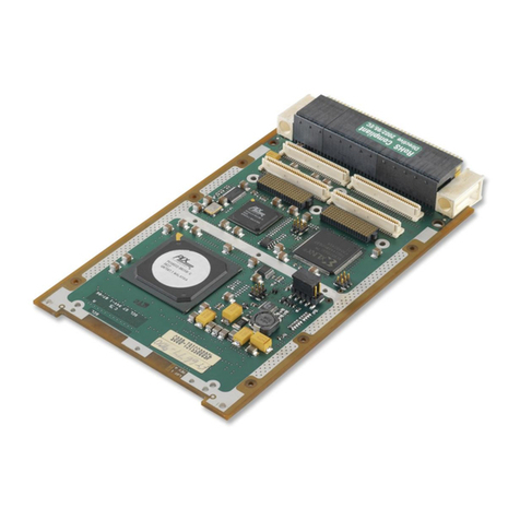
abaco systems FMC168 User manual

UM031 FMC168/4/2 r1.7
UM031 www.abaco.com page 1 of 28
FMC168/4/2
User Manual
FMC168 / FMC164 / FMC162
Abaco Systems
Support Portal
This document is the property of Abaco Systems and may not be copied nor communicated to a
third party without the written permission Abaco Systems.
© Abaco Systems 2017

UM031 FMC168/4/2 r1.7
UM031 www.abaco.com page 2 of 28
Revision History
Document
Revision Changes Author Peer
Review Quality
Approval Date
1.0 Release -- -- -- 2013/07/05
1.1 Added LPC compatibility -- -- -- 2013/07/25
1.2 Added FMC162, 2-channel
variant -- -- -- 2014/03/18
1.3
Revised some descriptions
and fixed typos. -- -- -- 2014/04/07
1.4
Correction in main
characteristics table.
Corrected I2C and CPLD
information
-- -- -- 2014/06/17
1.5
Corrected external VCO part
number -- -- -- 2014/09/08
1.6
Removed reference to cutoff
filter in section -- -- -- 2015/03/06
1.7 Update to the Abaco format
Added description about
heatsink option in the cooling
section.
EBa JHN JDS 2017/03/27

UM031 FMC168/4/2 r1.7
UM031 www.abaco.com page 3 of 28
Table of Contents
1Acronyms and related documents............................................................................. 5
1.1 Acronyms................................................................................................................ 5
1.2 Related Documents................................................................................................. 5
2General description..................................................................................................... 6
3Installation ................................................................................................................... 7
3.1 Requirements and handling instructions.................................................................. 7
4Design .......................................................................................................................... 7
4.1 Physical specifications ............................................................................................ 7
4.1.1 Board Dimensions............................................................................................ 7
4.1.2 Front panel....................................................................................................... 7
4.2 Electrical specifications........................................................................................... 9
4.2.1 QDR LVDS mode............................................................................................. 9
4.2.2 DDR LVDS mode............................................................................................. 9
4.2.3 EEPROM ......................................................................................................... 9
4.2.4 Stacked FMC ................................................................................................... 9
4.2.5 JTAG...............................................................................................................10
4.3 Main characteristics................................................................................................10
4.4 Analog input channels............................................................................................11
4.4.1 AC coupling.....................................................................................................11
4.4.2 DC coupling ....................................................................................................11
4.5 External clock input................................................................................................12
4.6 External clock output..............................................................................................12
4.7 External trigger/sync input......................................................................................12
4.8 Clock tree...............................................................................................................12
4.8.1 Architecture.....................................................................................................12
4.8.2 PLL design......................................................................................................14
4.9 Power supply..........................................................................................................14
5Controlling the FMC168/4/2........................................................................................14
5.1 CPLD .....................................................................................................................15
5.2 Onboard monitoring................................................................................................16
6Environment................................................................................................................16
6.1 Temperature ..........................................................................................................16
6.2 Monitoring..............................................................................................................16
6.3 Cooling...................................................................................................................16
6.3.1 Convection cooling..........................................................................................17
6.3.2 Conduction cooling..........................................................................................17
7Safety...........................................................................................................................17
8EMC .............................................................................................................................17
9Ordering information..................................................................................................17
10 Warranty......................................................................................................................17
Appendix A FMC168/4/2 connector pin-out – QDR mode............................................19

UM031 FMC168/4/2 r1.7
UM031 www.abaco.com page 5 of 28
1 Acronyms and related documents
1.1 Acronyms
ADC
Analog-to-Digital Converter
DDR
Double Data Rate
DSP
Digital Signal Processing
EPROM
Erasable Programmable Read-Only Memory
FBGA
Fineline Ball Grid Array
FMC
FPGA Mezzanine Card
FPGA
Field Programmable Gate Array
JTAG
Join Test Action Group
LED
Light Emitting Diode
LVTTL
Low Voltage Transistor Logic level
LPC
Low Pin Count
LSB
Least Significant Bit(s)
LVDS
Low Voltage Differential Signaling
MGT
Multi-Gigabit Transceiver
MSB
Most Significant Bit(s)
PCB
Printed Circuit Board
PCI
Peripheral Component Interconnect
PCIe
PCI Express
PLL
Phase-Locked Loop
PMC
PCI Mezzanine Card
PSSR
Power Supply Rejection Ratio
QDR
Quadruple Data rate
SDRAM
Synchronous Dynamic Random Access memory
SRAM
Synchronous Random Access memory
TTL
Transistor Logic level
XMC
PCIe Mezzanine card
Table 1: Glossary
1.2 Related Documents
•FPGA Mezzanine Card (FMC) standard ANSI/VITA 57.1-2010
•Datasheet ADS42LB69 Nov 2012, Analog Devices
•Datasheet AD9517-3, Analog Devices
•Datasheet AD7291BCPZ Rev B, Analog Devices

UM031 FMC168/4/2 r1.7
UM031 www.abaco.com page 6 of 28
2 General description
The FMC168 is an eight channel ADC FMC daughter card. The card provides eight 16-bit
250MSPS ADC channels which can be clocked by an internal clock source (optionally locked
to an external reference) or an externally supplied sample clock. There is one trigger input for
customized sampling control. The FMC168 daughter card is mechanically and electrically
compliant to FMC standard (ANSI/VITA 57.1). The FMC168 has a high-pin count connector,
front panel I/O, and can be used in a conduction-cooled environment. A four channel variant,
the FMC164, and a two channel variant, the FMC162, are available and offer the same
features with fewer channels.
The design is based on TI’s ADS42LB69 dual-channel 16-bit 250MSPS ADC with
programmable DDR LVDS or QDR LVDS outputs. The analog signal input can be either AC-
coupled or DC-coupled connecting to SSMC coax connectors on the front panel. In addition,
the FMC164 and FMC162 offer optional differential inputs.
The FMC168/4/2 allows flexible control of sampling frequency and analog input gain through
the I2C communication bus. Furthermore the card is equipped with power supply and
temperature monitoring and offers several power-down modes to switch off unused
functions.
Reference Clock
or
Sample Clock
Trigger
ADC A
ADS42LB69
16-bit, 250 MSPS
FMC Connector
HPC 400 Pins (LPC compatible)
Clock Tree Clock
Status & Control
Clock [2x1 pair]
Clock
Output
ADC H
……….
……….
……….
……….
Monitoring
OPTIONAL
EEPROM
I2C
BOARD
CONTROL
CPLD
Data [8x4 pair]
Clock [2x1 pair] *
Data [8x4 pair] *
* HPC connections
Figure 1: FMC168 block diagram
Note1: Although the FMC168/4/2 is equipped with a HPC connector, it can be used in LPC
carrier hardware. The LVDS interface on LPC runs at 500MHz DDR for 250Msps sampling
rate. On HPC carriers the LVDS interface can be reduced to 250MHz DDR for 250Msps
sampling.
Note2: Over-range bit and frame signals are not available when targeting the LPC connector
only.

UM031 FMC168/4/2 r1.7
UM031 www.abaco.com page 7 of 28
3 Installation
3.1 Requirements and handling instructions
•Prevent electrostatic discharges by observing ESD precautions when handling the
card.
•Do not flex the card, and do not exceed the maximum torque specification on the
SSMC connectors.
•The FMC168/4/2 daughter card must be installed on a carrier card compliant to the
FMC standard.
•The FMC carrier card must support the low-pin count connector (160-pins) and may
support the high-pin count connector (400-pins).
•The FMC168/4/2 supports a VADJ voltage between +1.5V and +3.3V. The FMC
carrier must support VIO_B equal to VADJ.
4 Design
4.1 Physical specifications
4.1.1 Board Dimensions
The FMC168/4/2 card complies with the FMC standard known as ANSI/VITA 57.1. The card
is a single-width, conduction-cooled mezzanine module (with region 1 and front panel I/O).
Although the card has a front panel I/O, it is compatible with most fixed rib carrier cards. The
front area holds 10 SSMC connectors that do not conflict with a front rib on a carrier card.
The stacking height is 10mm.
4.1.2 Front panel
There are 10 SSMC connectors available from the front panel. From top to bottom; analog in
A to analog in D, clock in (CL), trigger in (TR), and analog in E to analog in H. Different front
panels are provided per variant.
Figure 2: FMC168 front panel layout
Figure 3: FMC164 front panel layout (single-ended)

UM031 FMC168/4/2 r1.7
UM031 www.abaco.com page 8 of 28
Figure 4: FMC162 front panel layout (single-ended)
The tables below provide the front label to A/D converter and FMC signal mappings. For the
FMC168, the mapping is 1-to-1.For the reduced channel variants, the front panel labels don’t
always match the FMC connector signal names. For example, data sampled from FMC162
input B is present on FMC connector CHC_D[3..0] (QDR mode). Refer to Appendix A and B
for all FMC pin assignments.
Front Label FMC168 FMC connector signal
names
A Input 1st A/D CHA_*
B Input 2nd A/D CHB_*
C Input 3rd A/D CHC_*
D Input 4th A/D CHD_*
E Input 5th A/D CHE_*
F Input 6th A/D CHF_*
G Input 7th A/D CHG_*
H Input 8th A/D CHH_*
Table 2: FMC168 Connector function assignment
FMC164 Single ended FMC164 Differential
Font
Label Input FMC connector
signal names Font
Label Input FMC connector
signal names
A Input 1st A/D CHA_* A Non-Inverted input 1st A/D CHA_*
B Inverted input 1st A/D
B Input 2nd A/D CHC_* C Non-Inverted input 2nd A/D CHC_*
D Inverted input 2nd A/D
C Input 3rd A/D CHE_* E Non-Inverted input 3rd A/D CHE_*
F Inverted input 3rd A/D
D Input 4th A/D CHG_* G Non-Inverted input 4th A/D CHG_*
H Inverted input 4th A/D
Table 3: FMC164 Connector function assignment

UM031 FMC168/4/2 r1.7
UM031 www.abaco.com page 9 of 28
FMC162 Single ended FMC162 Differential
Font
Label Input FMC connector
signal names Font
Label Input FMC connector
signal names
A Input 1st A/D CHA_* A Non-Inverted input 1st A/D CHA_*
B Inverted input 1st A/D
B Input 2nd A/D CHC_* C Non-Inverted input 2nd A/D CHC_*
D Inverted input 2nd A/D
Table 4: FMC162 Connector function assignment
4.2 Electrical specifications
The FMC168/4/2 card is designed to operate in LVDS mode. The connections on FMC bank
LA allow simultaneous sampling of eight (FMC168), four (FMC164), or two (FMC162)
channels. This is referred to as QDR LVDS mode. With the use of the connections on FMC
bank HA and HB, the digital interface rate can be reduced by a factor of two. This is referred
to as DDR LVDS mode.
4.2.1 QDR LVDS mode
In QDR LVDS mode each channel uses four LVDS pairs at 500MHz DDR, with a sampling
frequency of 250MHz. This mode can be used by both LPC and HPC carrier hardware.
4.2.2 DDR LVDS mode
In DDR LVDS mode each channel uses eight LVDS pairs at 250MHz DDR, with a sampling
frequency of 250MHz. This mode can only be used by HPC carrier hardware.
4.2.3 EEPROM
The FMC168/4/2 card carries a serial EEPROM (M24C02-WDW6) which is accessible from
the carrier card through the I2C bus. The EEPROM is powered by 3P3VAUX. The standby
current is only 0.01µA when SCL and SDA are kept at 3P3VAUX level. The EEPROM is
write-protected by default.
4.2.4 Stacked FMC
The FMC connector is referred as the top FMC connector as defined in ANSI/VITA 57.1. The
FMC168/4/2 can be used in a stacked environment when the bottom FMC connector is
mounted. The following connections are available between the top and bottom FMC
connector:
•All gigabit data signals (DP[0..9]_M2C_P/N, DP[0..9]_C2M_P/N)
•All gigabit reference clocks (GBTCLK[0..1]_M2C_P/N)
•RES0
•3P3VAUX, 3P3V, 12P0V, VADJ
•JTAG (see section 4.2.3)

UM031 FMC168/4/2 r1.7
UM031 www.abaco.com page 10 of 28
4.2.5 JTAG
The FMC168/4/2 has a CPLD device in the JTAG chain. The TDO pin of the CPLD is
normally connected to the TDO pin of the top FMC connector through a buffer to ensure
continuity of the JTAG chain.
In a stacked environment, the TDO pin of the CPLD will be decoupled from the TDO pin of
the top FMC connector by the PRST_M2C_L signal coming from the bottom connector.
TRST#, TCK, TMS, and TDO are directly connected between top and bottom connector.
There is a build option to bypass the CPLD after factory programming for customers
requiring a direct connection between TDI and TDO on the top connector. Contact Abaco for
detailed information.
TDI TDO
TDI TDO PRSNT_M2C_L
PRSNT_M2C_L
Top connector (to FMC carrier)
Bottom connector (to stacked FMC)
3P3V
OE
TMS
TMS
TCK
TCK
TRST#
TRST#
CPLD
Figure 5: JTAG connections
4.3 Main characteristics
Analog inputs
Number of channels 8 (FMC168)
4 (FMC164)
2 (FMC162)
Channel resolution 16-bit
Input voltage range 1Vp-p (4dBm) to 2Vp-p (10 dBm) programmable
Input gain Programmable from -2dB to 6dB in 0.5dB steps
Input impedance 50Ω
Analog input bandwidth 500MHz (typical)
SNR (Fs = 250MHz)
SNR (Fin=11MHz): 70.643 dB (typical)
SNR (Fin=32MHz): 70.094 dB (typical)
SNR (Fin=64MHz): 66.576 dB (typical)
SNR (Fin=124MHz) 63.472 dB (typical)
SFDR (Fs = 250MHz)
SFDR (Fin=11MHz): 62.465 dBc (typical)
SFDR (Fin=32MHz): 67.082 dBc (typical)
SFDR (Fin=64MHz): 78.212 dBc (typical)
SFDR (Fin=124MHz) 72.499 dBc (typical)
External sampling clock input
Input Level 0dBm typical (LVTTL level supported)

UM031 FMC168/4/2 r1.7
UM031 www.abaco.com page 11 of 28
Input impedance 50Ω
Input bandwidth 4.5 MHz to 250 MHz. (AC coupled)
External reference clock input
Input Level 0dBm typical (LVTTL level supported)
Input impedance 50Ω
Input bandwidth 4.5 MHz to 250 MHz. (AC-coupled)
External reference clock output
Output Level LVTLL/LVCMOS
External Trigger input
Format LVTLL/LVCMOS (TTL compliant)
Threshold level 1.25V
Frequency range Up to 125 MHz
ADC Output
Output data width QDR LVDS mode; 4-pairs DDR per channel (LPC/HPC)
DDR LVDS mode; 8-pairs DDR per channel (HPC only)
Data Format Offset binary or 2’s complement (programmable)
Sampling Frequency Range 250MHz internal clock
Up to 250MHz external clock
Table 5 : FMC168/4/2 daughter card main characteristics
4.4 Analog input channels
The analog input signals are connected to the FMC168/4/2 via SSMC connectors on the
front panel. Each channel can be assembled as an AC-coupled or DC-coupled input.
Optionally, the FMC164/2 supports differential inputs using two connectors per channel. A
125MHz low-pass input filter can be assembled.. The filter option needs to be specified at the
time of ordering. See Chapter 9 Ordering information for details.
DC
Coupling LPF ADC
AC
Coupling
IN
Filter Bypass
Figure 6: Analog input block diagram
4.4.1 AC coupling
The AC-coupled input option uses wideband RF transformers (TC4-1W, 3-800MHz). Two
transformers are used head-to-head to compensate for imbalance and reduce harmonic
distortion. The input impedance is matched to 50Ω.
4.4.2 DC coupling
The DC-coupled input option uses Analog Devices ADA4939-1 ADC driver. The gain (G) is
set to one giving maximum input bandwidth (BW). To reduce harmonic distortion in DC-

UM031 FMC168/4/2 r1.7
UM031 www.abaco.com page 12 of 28
coupled applications, there is a provision for an optional 5th order low-pass. The filter design
can be specified at the time of ordering. Please contact your sales channel for more details.
4.5 External clock input
There is one clock input on the front panel that can serve as sampling clock input or as
reference clock input if the internal clock is desired. Refer also to Chapter 4.8 for more
information about the clock tree.
Note 1: When internal clock is enabled and there is no need for an external reference,
it is highly recommended to leave the clock input unconnected to prevent interference
with the internal clock.
Note 2: When external clock is enabled, the onboard VCO might cause interference.
The VCO cannot be powered down on the FMC168/4 r1.0. Please contact Abaco to
have the onboard VCO disabled for external clock applications.
4.6 External clock output
The external clock output will be a LVTTL output driven from the AD9517. It’s a build option.
The trigger connector can be used as clock output. Contact Abaco for details.
4.7 External trigger/sync input
The external trigger input can be configured in different ways depending on the build option.
The trigger input can be 50Ωterminated, accepting most common high-speed signalling
standards like single-ended LVPECL. By default, the 50Ω termination is not mounted in order
to support LVTTL/LVCMOS and similar input standards. By default, the input is single-ended
and DC-coupled with an input impedance of approximately 2.5kΩ. The input threshold is
approximately 1.25V.
Optionally, the trigger input can be used as sync input, synchronizing local A/D converters or
multiple cards.
TRIGGER
Any Level
to LVDS
1:2 Fanout
SYNC_FROM_CPLD_P/N
Fs/4 from Clock Tree
LVDS
MUX
to FMC
SYNCSRC_SEL[1:0]
SSYNC_FROM_FPGA_P/N
ADC#1
ADC#2
ADC#3
ADC#4
ADCLK
944
Figure 7: A/D Synchronization topology
4.8 Clock tree
4.8.1 Architecture
The FMC168/4/2 card offers a clock architecture that combines flexibility and high
performance. Components have been chosen in order to minimize jitter and phase noise to

UM031 FMC168/4/2 r1.7
UM031 www.abaco.com page 13 of 28
reduce degradation of the data conversion performance. The user may choose to use an
external sampling clock or an internal sampling clock.
The AD9517 PLL and clock distribution device is the base of the clock tree. The external
clock input is routed through RF switches and transformers that drive the reference input on
the AD9517 (REFIN) and the primary clock input on the AD9517 (CLK). The primary clock
input can be connected directly to the distribution section of the AD9517.
A VCO is connected to the primary clock input (CLK). This clock input connects to both the
clock distribution section and the PLL section. In order to tune the VCO to a certain
frequency, a reference clock on REFIN is required. An onboard oscillator can be enabled if
there is no external reference connected. The onboard oscillator is connected in parallel with
the clock input behind the RF transformer. To avoid interference, there should be no
signal applied to clock input when internal reference is used.
Figure 8: Clock tree
The AD9517 outputs are allocated as follows:
- OUT0is an LVPECL output and is used for clocking the ADC devices through an
ADCLK944 fan-out buffer. OUT 1-3 are unused and must be disabled for best
performance.
- OUT4 is connected to the synchronization logic and must be programmed to LVDS
output if used.
- OUT5A is used as optional clock output (through the trigger connector) and must be
programmed to LVCMOS if used. OUT5B is unused and should be disabled.
- OUT6 is used as optional clock connected to FMC connection CLK0_M2C_P/N and must
be programmed to LVDS if used.
- OUT7A is used as spare clock to the CPLD and must be disabled. OUT7B is unused and
must be disabled.
Clock
ToFMC
To CPLD
VCO
1.25 GHz
XTAL
100MHz
Loop
Filter
To ADC
devices
RF
Switch
RF
Switch
To Sync
CLKSRC_SEL0
CLKSRC_SEL1
CLKSRC_SEL2
Π-attn
Optional
Build option

UM031 FMC168/4/2 r1.7
UM031 www.abaco.com page 14 of 28
4.8.2 PLL design
The PLL functionality of the AD9517 is used to operate from an internal sampling clock. The
VCO is a high-performance oscillator (CLV1225A-LF). As a build option, the internal VCO of
the AD9517 can be enabled. Contact Abaco for details.
The default loop filter is designed for a phase detector frequency of 10MHz, loop bandwidth
of 10kHz, phase margin of 45 deg, and a charge pump of 4.8mA.
Figure 9: VCO loop filter design
4.9 Power supply
Power is supplied to the FMC168/4/2 card through the FMC connector. The pin current rating
is 2.7A, but the overall maximum is limited according to Table 6.
Voltage
# Pins
Max Amps
Max Watt
+3.3V
4
3 A
10 W
+12V
2
1 A
12 W
VADJ (+1.8V / +2.5V)
4
4 A
10 W
VIO_B (VADJ)
2
1.15 A
2.3 W
Table 6: FMC standard power specification
The power provided by the carrier card can be very noisy. Special care is taken with the
power supply generation on the FMC168/4/2 card to minimize the effect of power supply
noise on clock generation and data conversion. However, properly filtered power supplies
from the FMC carrier are recommended.
Table 7 shows typical currents per power rail. VIO_B is connected to VADJ on the
FMC168/4/2. Current drawn from VADJ by the FMC168/4/2 is minimal. The typical power
consumption is 13.5W.
Power plane
Typical
Maximum
VADJ
IVIO_B, typ
IVIO_B, max
3P3V
1344mA
12P0V
750mA
3P3VAUX (Operating)
3P3VAUX (Standby)
0.1 mA
0.01 µA
3 mA
1 µA
Table 7: Typical / Maximum current drawn from FMC carrier card
5 Controlling the FMC168/4/2
Good knowledge of the internal structure and communication protocol of relevant onboard
devices is required for controlling the FMC168/4/2. Please refer to the datasheets mentioned
R1
51.0
C2
1.00uF
C1
68.0nF R2
100 C3
33.0nF Ct
0F
VCO
CLV1225A

UM031 FMC168/4/2 r1.7
UM031 www.abaco.com page 15 of 28
in the Related Documents section of this user manual for detailed information. The
FMC168/4/2 is designed to be controlled through the I2C interface.
Device I2C Address GA(0..1)
M24C02 (EEPROM) 10100XX XX=GA(0..1)
AD7291 (Voltage Monitor) 010XXXX XXXX GA(1..0)
1111 00
1100 01
0011 10
0000 11
CPLD (Board Control) 01111XX XX=GA(1..0)
Table 8: I2C slave addresses
Note: According to ANSI/VITA 57.1, the least significant address bit of the EEPROM
connects to GA1. EEPROM address bit 1 connects to GA0.
5.1 CPLD
The FMC168/4/2 has an onboard CPLD (XC2C256 CP132) used to control different devices
on board. The CPLD communicates with the carrier hardware via an I2C interface and acts
as an I2C-to-SPI bridge. Refer to the Appendix for register and control details.
3.3V
BANK
ADG3304
VADJ3.3V
4
4FMC_TO_CPLD[3..0]
I2C
FMC ConnectorCPLD
1.8V
BANK
Signals to:
AD9517
Signals to:
ADS42LB69
Figure 10: FMC control interface
The FMC_TO_CPLD connections are for future use. The connections are only available on
HPC carrier hardware.

UM031 FMC168/4/2 r1.7
UM031 www.abaco.com page 16 of 28
5.2 Onboard monitoring
The FMC168/4/2 holds one AD7291 device for monitoring several power supply voltages and
temperature on the board. The device can be programmed and read out through the I2C
connection on the FMC connector.
Parameter: Connection Formula
On-chip temperature
External temperature Not implemented
External AIN0 1.8V Digital AIN0 * 1
External AIN1 1.8V Analog AIN1 * 1
External AIN2 3.3V Analog AIN2 * 2
External AIN3 VADJ AIN3 * 2
External AIN4 3.3V Digital Clock AIN4 * 2
External AIN5 3.3V Analog Clock AIN5 * 2
External AIN6 VCP AIN6 * 3.128
External AIN7 1.8V Analog Clock AIN7 * 1
Table 9: Temperature and voltage parameters
6 Environment
6.1 Temperature
Operating temperature
•0°C to +70°C (Commercial)
•-40°C to +85°C (Industrial)
Storage temperature:
•-40°C to +120°C
6.2 Monitoring
One AD7291 device may be used to monitor the voltage on the different power rails and the
environment temperature.
It is recommended that the carrier card and/or host software uses the power-down features
in the different devices in the case the temperature is too high. Normal operations can
resume once the temperature is within the operating conditions boundaries.
6.3 Cooling
Two different types of cooling will be available for the FMC168/4/2.

UM031 FMC168/4/2 r1.7
UM031 www.abaco.com page 17 of 28
6.3.1 Convection cooling
The air flow provided by the fans of the chassis the FMC168/4/2 is enclosed in will dissipate
the heat generated by the onboard components. A minimum airflow of 300 LFM is
recommended. Optional Heat Sync Available, Contact sales and ask for Custom Option -
C108.
For standalone operations (such as on a Xilinx development kit), it is highly recommended to
blow air across the FMC to ensure that the temperature of the devices is within the allowed
range. Abaco’s warranty does not cover boards on which the maximum allowed temperature
has been exceeded.
6.3.2 Conduction cooling
In demanding environments, the ambient temperature inside a chassis could be close to the
operating temperature defined in this document. It is very likely that in these conditions the
junction temperature of power consuming devices will exceed the operating conditions
recommended by the device manufacturers (mostly +85°C). While a low profile heat sink
coupled with sufficient air flow might be sufficient to maintain the temperature within
operating boundaries, some active cooling would yield better results and would certainly help
with resuming operations much faster if the devices are disabled because of a temperature
“over range”.
7 Safety
This module presents no hazard to the user. Supplies used to power the FMC module shall
not exceed the voltage and current limits as specified by ANSI/VITA 57.1-2010. Source
supplies should be current limited to max.8A and/or power limited to max.150VA. Abaco
circuit boards have a flammability rating of at least V1 as specified by UL 94.
8 EMC
This module is designed to operate within an enclosed host system built to provide EMC
shielding. Operation within the EU EMC guidelines is not guaranteed unless it is installed
within an adequate host system. This module is protected from damage by fast voltage
transients originating from outside the host system which may be introduced through the
system.
9 Ordering information
See http://www.4dsp.com/FMC168 or http://www.4dsp.com/FMC164
10 Warranty
Hardware Software/Firmware
Basic Warranty
(included) 1 Year from Date of Shipment 90 Days from Date of Shipment
Extended Warranty 2 Years from Date of Shipment 1 Year from Date of Shipment

UM031 FMC168/4/2 r1.7
UM031 www.abaco.com page 19 of 28
Appendix A FMC168/4/2 connector pin-out – QDR mode
AV57.1 LPC Pin Signal AV57.1 HPC Pin Signal AV57.1 HPC Pin Signal
CLK0_M2C_N H5 CLK_TO_FPGA_N HA00_N_CC F5 CHA_FRM_N HB00_N_CC K26 CHF_CLK_N
CLK0_M2C_P H4 CLK_TO_FPGA_P HA00_P_CC F4 CHA_FRM_P HB00_P_CC K25 CHF_CLK_P
CLK1_M2C_N G3 EXT_TRIGGER_N HA01_N_CC E3 N.C. HB01_N J25 N.C.
CLK1_M2C_P G2 EXT_TRIGGER_P HA01_P_CC E2 N.C. HB01_P J24 N.C.
CLK2_BIDIR_N K5 SYNC_FROM_FPGA_P HA02_N K8 CHC_FRM_N HB02_N F23 N.C.
CLK2_BIDIR_P K4 SYNC_FROM_FPGA_N HA02_P K7 CHC_FRM_P HB02_P F22 N.C.
CLK3_BIDIR_N J3 N.C. HA03_N J7 N.C. HB03_N E22 CHF_OVR
CLK3_BIDIR_P J2 N.C. HA03_P J6 N.C. HB03_P E21 N.C.
LA00_N_CC G7 CHA_CLK_N HA04_N F8 N.C. HB04_N F26 CHH_CLK_N
LA00_P_CC G6 CHA_CLK_P HA04_P F7 CHC_OVR HB04_P F25 CHH_CLK_P
LA01_N_CC D9 CHA_D0_N
HA05_N E7 CHA_OVR HB05_N E25 CHH_FRM_N
LA01_P_CC D8 CHA_D0_P
HA05_P E6 N.C. HB05_P E24 CHH_FRM_P
LA02_N H8 CHA_D3_N
HA06_N K11 CHB_CLK_N HB06_N_CC K29 CHF_FRM_N
LA02_P H7 CHA_D3_P
HA06_P K10 CHB_CLK_P HB06_P_CC K28 CHF_FRM_P
LA03_N G10 CHA_D2_N
HA07_N J10 N.C. HB07_N J28 N.C.
LA03_P G9 CHA_D2_P
HA07_P J9 N.C. HB07_P J27 N.C.
LA04_N H11 CHC_D0_N
HA08_N F11 N.C. HB08_N F29 N.C.
LA04_P H10 CHC_D0_P
HA08_P F10 N.C. HB08_P F28 CHH_OVR
LA05_N D12 CHA_D1_N
HA09_N E10 CHC_CLK_N HB09_N E28 N.C.
LA05_P D11 CHA_D1_P
HA09_P E9 CHC_CLK_P HB09_P E27 N.C.
LA06_N C11 CHC_D3_N
HA10_N K14 CHB_FRM_N HB10_N K32 FMC_TO_CPLD1
LA06_P C10 CHC_D3_P
HA10_P K13 CHB_FRM_P HB10_P K31 FMC_TO_CPLD0
LA07_N H14 CHC_D2_N
HA11_N J13 CHB_OVR HB11_N J31 FMC_TO_CPLD3
LA07_P H13 CHC_D2_P
HA11_P J12 N.C. HB11_P J30 FMC_TO_CPLD2
LA08_N G13 CHC_D1_N
HA12_N F14 N.C. HB12_N F32 N.C.
LA08_P G12 CHC_D1_P
HA12_P F13 N.C. HB12_P F31 N.C.
LA09_N D15 CHB_D0_N
HA13_N E13 CHD_CLK_N HB13_N E31 N.C.
LA09_P D14 CHB_D0_P
HA13_P E12 CHD_CLK_P HB13_P E30 N.C.
LA10_N C15 CHB_D1_N
HA14_N J16 N.C. HB14_N K35 N.C.
LA10_P C14 CHB_D1_P
HA14_P J15 N.C. HB14_P K34 N.C.
LA11_N H17 CHB_D2_N
HA15_N F17 N.C. HB15_N J34 N.C.
LA11_P H16 CHB_D2_P
HA15_P F16 N.C. HB15_P J33 N.C.
LA12_N G16 CHB_D3_N
HA16_N E16 CHD_FRM_N HB16_N F35 N.C.
LA12_P G15 CHB_D3_P
HA16_P E15 CHD_FRM_P HB16_P F34 N.C.
LA13_N D18 CHD_D0_N
HA17_N_CC K17 N.C. HB17_N_CC K38 N.C.
LA13_P D17 CHD_D0_P
HA17_P_CC K16 CHD_OVR HB17_P_CC K37 N.C.
LA14_N C19 CHD_D2_N
HA18_N J19 CHE_FRM_N HB18_N J37 N.C.
LA14_P C18 CHD_D2_P
HA18_P J18 CHE_FRM_P HB18_P J36 N.C.
LA15_N H20 CHD_D1_N
HA19_N F20 CHE_OVR HB19_N E34 N.C.
LA15_P H19 CHD_D1_P
HA19_P F19 N.C. HB19_P E33 N.C.
LA16_N G19 CHD_D3_N
HA20_N E19 CHG_FRM_N HB20_N F38 N.C.
LA16_P G18 CHD_D3_P
HA20_P E18 CHG_FRM_P HB20_P F37 N.C.
LA17_N_CC D21 CHE_CLK_N
HA21_N K20 CHG_CLK_N HB21_N E37 N.C.
LA17_P_CC D20 CHE_CLK_P
HA21_P K19 CHG_CLK_P HB21_P E36 N.C.
LA18_N_CC C23 CHE_D3_N
HA22_N J22 N.C.

UM031 FMC168/4/2 r1.7
UM031 www.abaco.com page 20 of 28
AV57.1 LPC Pin Signal AV57.1 HPC Pin Signal AV57.1 HPC Pin Signal
LA18_P_CC C22 CHE_D3_P
HA22_P J21 N.C.
LA19_N H23 CHE_D0_N
HA23_N K23 N.C. GBTCLK1_M2C_N B21 GBTCLK1_N
LA19_P H22 CHE_D0_P
HA23_P K22 CHG_OVR GBTCLK1_M2C_P B20 GBTCLK1_P
LA20_N G22 CHE_D2_N
LA20_P G21 CHE_D2_P
LA21_N H26 CHG_D0_N
LA21_P H25 CHG_D0_P
LA22_N G25 CHE_D1_N
DP1_C2M_N A23 DP_C2M_N<1>
LA22_P G24 CHE_D1_P
DP1_C2M_P A22 DP_C2M_P<1>
LA23_N D24 CHG_D3_N
DP1_M2C_N A3 DP_M2C_N<1>
LA23_P D23 CHG_D3_P
DP1_M2C_P A2 DP_M2C_P<1>
LA24_N H29 CHF_D0_N
DP2_C2M_N A27 DP_C2M_N<2>
LA24_P H28 CHF_D0_P
DP2_C2M_P A26 DP_C2M_P<2>
LA25_N G28 CHG_D1_N
DP2_M2C_N A7 DP_M2C_N<2>
LA25_P G27 CHG_D1_P
DP2_M2C_P A6 DP_M2C_P<2>
LA26_N D27 CHG_D2_N
DP3_C2M_N A31 DP_C2M_N<3>
LA26_P D26 CHG_D2_P
DP3_C2M_P A30 DP_C2M_P<3>
LA27_N C27 CHF_D1_N
DP3_M2C_N A11 DP_M2C_N<3>
LA27_P C26 CHF_D1_P
DP3_M2C_P A10 DP_M2C_P<3>
LA28_N H32 CHF_D2_N
DP4_C2M_N A35 DP_C2M_N<4>
LA28_P H31 CHF_D2_P
DP4_C2M_P A34 DP_C2M_P<4>
LA29_N G31 CHF_D3_N
DP4_M2C_N A15 DP_M2C_N<4>
LA29_P G30 CHF_D3_P
DP4_M2C_P A14 DP_M2C_P<4>
LA30_N H35 CHH_D0_N
DP5_C2M_N A39 DP_C2M_N<5>
LA30_P H34 CHH_D0_P
DP5_C2M_P A38 DP_C2M_P<5>
LA31_N G34 CHH_D2_N
DP5_M2C_N A19 DP_M2C_N<5>
LA31_P G33 CHH_D2_P
DP5_M2C_P A18 DP_M2C_P<5>
LA32_N H38 CHH_D1_N
DP6_C2M_N B37 DP_C2M_N<6>
LA32_P H37 CHH_D1_P
DP6_C2M_P B36 DP_C2M_P<6>
LA33_N G37 CHH_D3_N
DP6_M2C_N B17 DP_M2C_N<6>
LA33_P G36 CHH_D3_P
DP6_M2C_P B16 DP_M2C_P<6>
DP7_C2M_N B33 DP_C2M_N<7>
GBTCLK0_M2C_
N
D5 GBTCLK0_N CLK_DIR B1 ‘1’ DP7_C2M_P B32 DP_C2M_P<7>
GBTCLK0_M2C_P D4 GBTCLK0_P PG_M2C F1 PG_M2C DP7_M2C_N B13 DP_M2C_N<7>
DP0_C2M_N C3 DP_C2M_N<0> DP7_M2C_P B12 DP_M2C_P<7>
DP0_C2M_P C2 DP_C2M_P<0> DP8_C2M_N B29 DP_C2M_N<8>
DP0_M2C_N C7 DP_M2C_N<0> DP8_C2M_P B28 DP_C2M_P<8>
DP0_M2C_P C6 DP_M2C_P<0> DP8_M2C_N B9 DP_M2C_N<8>
DP8_M2C_P B8 DP_M2C_P<8>
I2C_SCL C30 I2C_SCL DP9_C2M_N B25 DP_C2M_N<9>
I2C_SDA C31 I2C_SDA DP9_C2M_P B24 DP_C2M_P<9>
PG_C2M D1 PG_C2M DP9_M2C_N B5 DP_M2C_N<9>
DP9_M2C_P B4 DP_M2C_P<9>
Table 10: FMC168/4/2 - QDR MODE (yellow cells are N.C. on FMC164 and FMC162, blue cells
are N.C. on FMC162)
This manual suits for next models
2
Table of contents
Other abaco systems Computer Hardware manuals
Popular Computer Hardware manuals by other brands

Bitspower
Bitspower Premium Cubiod Reservoir 150 D5 installation guide

Compex
Compex wpj558 Hardware guide

Yamaha
Yamaha EMP100 supplementary guide

EK-Quantum
EK-Quantum Vector RTX 3080/3090 Backplate user guide

Renesas
Renesas Stream it quick start

Fujitsu Siemens Computers
Fujitsu Siemens Computers POCKET LOOX N100 series operating instructions