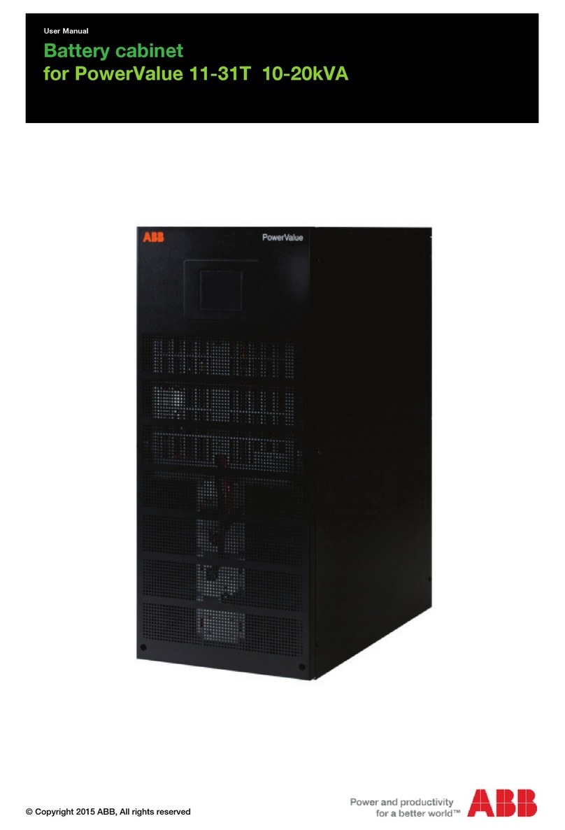
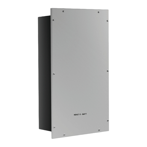
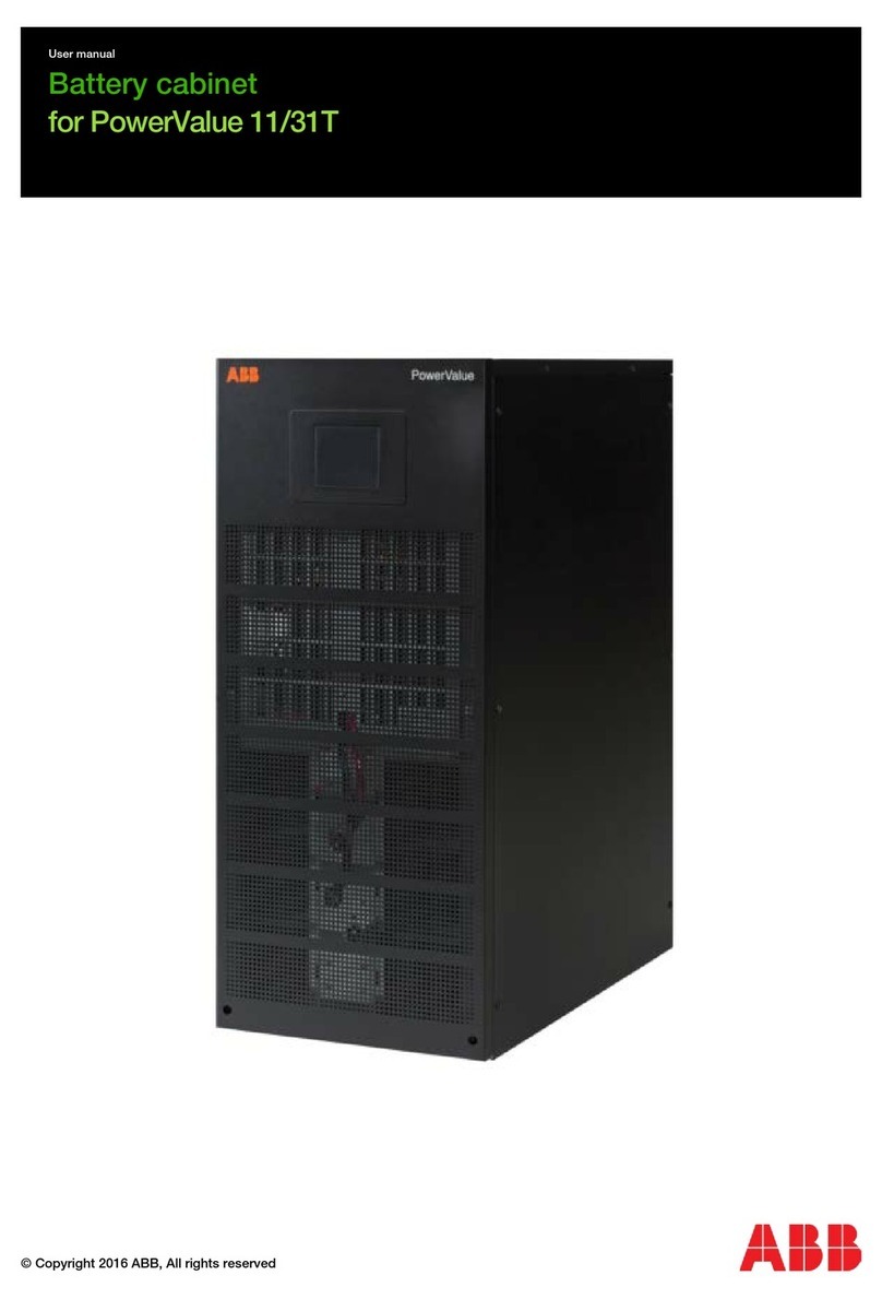
ABB RT G2 5-10 kVA UL User manual

—
USER MANUAL
External battery module
For RT G2 5-10 kVA UL
PREPARED: Elvan Chen
STATUS
SECURITY LEVEL: PublicApproved
APPROVED: Patricia Kuenzle DOCUMENT KIND: Operating manual
OWNING ORGANIZATION:
DOCUMENT ID: 4NWD005661 REV: A LANG: EN
PAGE:
1 / 20ABB Switzerland Ltd.
© Copyright 2022 ABB. All rights reserved.

2EXTERNAL BATTERY MODULE FOR RT G2 5-10 KVA UL
STATUS:
Approved
SECURITY LEVEL:
Public
DOCUMENT ID:
4NWD005661
REV:
A
LANG:
EN
PAGE:
2 / 20
© Copyright 2022 ABB. All rights reserved.
—
Contents
1 Important safety instructions . . . . . . . . . . . . . . . . . . . . . . . . . . . . . . . . . 3
1.1 Save these instructions . . . . . . . . . . . . . . . . . . . . . . . . . . . . . . . . . . . 3
1.2 Safety symbols and warnings . . . . . . . . . . . . . . . . . . . . . . . . . . . . . . . 3
1.3 Important Safety Warnings. . . . . . . . . . . . . . . . . . . . . . . . . . . . . . . . . 4
1.4 UPS disposal and recycling . . . . . . . . . . . . . . . . . . . . . . . . . . . . . . . . . 5
1.4.1 For professional users in the European Union . . . . . . . . . . . . . . . . . 5
1.4.2 For disposal in countries outside of the European Union . . . . . . . . . . 5
1.5 Certification standards . . . . . . . . . . . . . . . . . . . . . . . . . . . . . . . . . . . 6
2 Introduction . . . . . . . . . . . . . . . . . . . . . . . . . . . . . . . . . . . . . . . . . . . . 7
2.1 Environmental protection . . . . . . . . . . . . . . . . . . . . . . . . . . . . . . . . . 7
2.1.1 Substances . . . . . . . . . . . . . . . . . . . . . . . . . . . . . . . . . . . . . . . 7
2.1.2 Packing . . . . . . . . . . . . . . . . . . . . . . . . . . . . . . . . . . . . . . . . . 7
3 General characteristics . . . . . . . . . . . . . . . . . . . . . . . . . . . . . . . . . . . . . 8
3.1 Rear Panel View . . . . . . . . . . . . . . . . . . . . . . . . . . . . . . . . . . . . . . . . . 8
4 Installation . . . . . . . . . . . . . . . . . . . . . . . . . . . . . . . . . . . . . . . . . . . . . 9
4.1 Inspecting the equipment . . . . . . . . . . . . . . . . . . . . . . . . . . . . . . . . . 9
4.2 Unpacking the Unit. . . . . . . . . . . . . . . . . . . . . . . . . . . . . . . . . . . . . . 9
4.3 Check the inside package . . . . . . . . . . . . . . . . . . . . . . . . . . . . . . . . . 10
4.4 Installing the EBM . . . . . . . . . . . . . . . . . . . . . . . . . . . . . . . . . . . . . 10
4.4.1 Install in the rack position. . . . . . . . . . . . . . . . . . . . . . . . . . . . . .11
4.4.2 Install in the tower position . . . . . . . . . . . . . . . . . . . . . . . . . . . .11
4.4.3 Connecting with UPS and Other Battery Pack . . . . . . . . . . . . . . . . 12
5 Battery Installation . . . . . . . . . . . . . . . . . . . . . . . . . . . . . . . . . . . . . . . 13
6 Specification . . . . . . . . . . . . . . . . . . . . . . . . . . . . . . . . . . . . . . . . . . . 17
6.1 EBM Configuration . . . . . . . . . . . . . . . . . . . . . . . . . . . . . . . . . . . . . .17
6.2 Physical Parameter . . . . . . . . . . . . . . . . . . . . . . . . . . . . . . . . . . . . . .17
6.3 Certifications . . . . . . . . . . . . . . . . . . . . . . . . . . . . . . . . . . . . . . . . .17
6.4 Environmental. . . . . . . . . . . . . . . . . . . . . . . . . . . . . . . . . . . . . . . . 18
7 Storage & Maintenance. . . . . . . . . . . . . . . . . . . . . . . . . . . . . . . . . . . . . 19
7.1 Storage . . . . . . . . . . . . . . . . . . . . . . . . . . . . . . . . . . . . . . . . . . . . 19

3
EXTERNAL BATTERY MODULE FOR RT G2 5-10 KVA UL
STATUS:
Approved
SECURITY LEVEL:
Public
DOCUMENT ID:
4NWD005661
REV:
A
LANG:
EN
PAGE:
3 / 20
© Copyright 2022 ABB. All rights reserved.
—
1 Important safety instructions
—
1.1 Save these instructions
THIS CHAPTER CONTAINS IMPORTANT SAFETY INSTRUCTIONS. READ IT
CAREFULLY BEFORE DISASSEMBLING THE UNIT.
NOTE
THIS MANUAL CONTAINS IMPORTANT INSTRUCTIONS THAT SHOULD
BE FOLLOWED DURING THE INSTALLATION AND MAINTENANCE OF
THE EBM.
THE EBM MODELS THAT ARE COVERED IN THIS MANUAL ARE INTENDED
FOR INSTALLATION IN ENVIRONMENTS WHERE TEMPERATURES ARE
WITHIN 0 TO 40 °C ANDARE FREE OF CONDUCTIVE CONTAMINANTS.
—
1.2 Safety symbols and warnings
Follow all operating and user instructions.
THIS SYMBOL IN CONJUNCTION WITH THE SIGNAL WORD “DANGER”
INDICATES AN IMMINENT ELECTRICAL HAZARD.
FAILURE TO OBSERVE THE RELATED SAFETY NOTE MAY CAUSE INJURY,
DEATH OR EQUIPMENT DAMAGE.
THIS SYMBOL IN CONJUNCTION WITH THE SIGNAL WORD “WARNING”
INDICATES A POTENTIALLY DANGEROUS SITUATION.
FAILURE TO OBSERVE MAY CAUSE INJURY, DEATH OR EQUIPMENT DAMAGE.
THIS SYMBOL INDICATES A SAFETY NOTE: “ATTENTION! HAZARDOUS
VOLTAGE!”
INSTALLATION BY A CERTIFIED SERVICE ENGINEER ONLY.”
THIS SYMBOL IN CONJUNCTION WITH THE SIGNAL WORD “NOTE” INDICATES
OPERATOR TIPS OR PARTICULARLY USEFUL OR IMPORTANT INFORMATION
FOR THE USE OF THE PRODUCT.
THIS SYMBOL AND WORDING DO NOT INDICATE A DANGEROUS SITUATION.
THIS SYMBOL INDICATES THAT READING THE INSTRUCTION MANUAL/
BOOKLET BEFORE STARTING WORK OR BEFORE OPERATING EQUIPMENT OR
MACHINERY IS COMPULSORY.
DO NOT DISPOSE OF WITH ORDINARY TRASH.

4EXTERNAL BATTERY MODULE FOR RT G2 5-10 KVA UL
STATUS:
Approved
SECURITY LEVEL:
Public
DOCUMENT ID:
4NWD005661
REV:
A
LANG:
EN
PAGE:
4 / 20
© Copyright 2022 ABB. All rights reserved.
—
1.3 Important Safety Warnings
Please comply with all warnings and operating instructions in this manual strictly. Save
this manual properly and read carefully the following instructions before installing the
unit. Do not operate this unit before reading through all safety information and operating
instructions carefully.
DANGER
This battery bank is connected to an UPS. There will be voltage at the
output terminals if the UPS is turned on even if the input AC Mains is not
available.
WARNING
Do not try to repair the unit yourself, contact your local supplier or your
warranty will be void.
NOTE
To eliminate any overheating of the battery bank, keep all ventilation
openings free from obstruction and do not place any foreign objects
on top of the battery bank. Keep the battery bank 20 cm away from the
wall.
NOTE
Make sure the battery bank is installed within the proper environment as
specified.
(0-40°C/32°F – 104°F and 5-95% non-condensing humidity)
NOTE
Do not install the battery bank under direct sunlight. Your warranty will
be void if the batteries fail due to overheating.
NOTE
This battery bank is designed for indoor use only.
NOTE
This battery bank is not designed for use in dusty, corrosive and salty
environment.
NOTE
The warranty for this battery bank will be void if water or other liquid
is spilt or poured directly onto the battery bank. Similarly we do
not warrant any damage to the battery bank if foreign objects are
deliberately or accidentally inserted into the battery bank enclosure.
NOTE
The battery will discharge naturally if the system is unused for a period
of time.
NOTE
It should be recharged every 2-3 months if unused. If this is not done,
then the warranty will be null and void. During normal operation, the
batteries will be automatically remained in charged condition.
NOTE
Servicing of Batteries Should be Performed or Supervised by Trained
Personnel with Knowledge of Batteries and the Required Precautions

5
EXTERNAL BATTERY MODULE FOR RT G2 5-10 KVA UL
STATUS:
Approved
SECURITY LEVEL:
Public
DOCUMENT ID:
4NWD005661
REV:
A
LANG:
EN
PAGE:
5 / 20
© Copyright 2022 ABB. All rights reserved.
NOTE
When replacing batteries, replace with the same quantity, type &
capacity.
WARNING
Do not dispose of battery or batteries in an open fire. The battery may
explode.
WARNING
Do not open or mutilate the batteries. The electrolyte from the batteries
is toxic and harmful to the skin and eyes.
WARNING
Risk of Electric Shock – Battery circuit is not isolated from AC, hazardous
Voltage may exist between battery terminals and ground. Test before
touching with bare hands.
WARNING
A Battery can present a risk of electrical shock and high short circuit
current.
The following precaution should be observed when working on
batteries:
1. Remove watches, rings, or other metal objects.
2. Use tools with insulated handles.
3. Wear rubber gloves and boots.
4. Do not lay tools or metal parts on top of batteries.
5. Disconnect charging source prior to connecting or
disconnecting battery terminals.
DANGER
Do not plug or unplug the battery connector if UPS works in DC
(discharging) mode.
—
1.4 UPS disposal and recycling
—
1.4.1 For professional users in the European Union
THE CROSSED WHEELED BIN SYMBOL ON THE PRODUCT(S) AND / OR
ACCOMPANYING DOCUMENTS MEANS THAT USED ELECTRICAL AND
ELECTRONIC EQUIPMENT (WEEE) SHOULD NOT BE MIXED WITH GENERAL
HOUSEHOLD WASTE.
IF YOU WISH TO DISPOSE OF ELECTRICAL AND ELECTRONIC EQUIPMENT
(EEE), PLEASE CONTACT YOUR DEALER OR SUPPLIER FOR FURTHER
INFORMATION.
CORRECT WASTE DISPOSAL OF THIS PRODUCT WILL HELP SAVE VALUABLE
RESOURCES AND PREVENT ANY POTENTIAL NEGATIVE EFFECTS ON HUMAN
HEALTH AND THE ENVIRONMENT, WHICH COULD OTHERWISE ARISE FROM
INAPPROPRIATE WASTE HANDLING

6EXTERNAL BATTERY MODULE FOR RT G2 5-10 KVA UL
STATUS:
Approved
SECURITY LEVEL:
Public
DOCUMENT ID:
4NWD005661
REV:
A
LANG:
EN
PAGE:
6 / 20
© Copyright 2022 ABB. All rights reserved.
—
1.4.2 For disposal in countries outside of the European Union
THE CROSSED WHEELED BIN SYMBOL IS ONLY VALID IN THE EUROPEAN
UNION (EU) MEANING THAT USED ELECTRICAL AND ELECTRONIC
EQUIPMENT (WEEE) SHOULD NOT BE MIXED WITH GENERAL
HOUSEHOLDWASTE.
IF YOU WISH TO DISPOSE OF THIS PRODUCT PLEASE CONTACT YOUR
LOCAL AUTHORITIES OR DEALER AND ASK FOR THE CORRECT METHOD OF
DISPOSAL.
CORRECT WASTE DISPOSAL OF THIS PRODUCT WILL HELP SAVE VALUABLE
RESOURCES AND PREVENT ANY POTENTIAL NEGATIVE EFFECTS ON HUMAN
HEALTH AND THE ENVIRONMENT, WHICH COULD OTHERWISE ARISE FROM
INAPPROPRIATE WASTE HANDLING
—
1.5 Certification standards
• Safety: UL 1778, CSA 107.3.
• IEC 61000-4-2 (ESD): level 3.
• Radiated: FCC CFR 47 Part 15 Class A.
• Conducted: FCC CFR 47 Part 15 Class A.
• IEC 61000-4-4 (EFT): level 3.
• IEC 61000-4-5 (Surge): level 2 (Line-Line),level 3(Line-Earth).
• IEC 61000-4-6 (CS): level 3.
• IEC 61000-4-8 (Power Frequency Magnetic Field Immunity): level 4.
• IEC 61000-2-2 (Low Frequency Signals)
• IEC 61000-4-3 (RS): level 3

7
EXTERNAL BATTERY MODULE FOR RT G2 5-10 KVA UL
STATUS:
Approved
SECURITY LEVEL:
Public
DOCUMENT ID:
4NWD005661
REV:
A
LANG:
EN
PAGE:
7 / 20
© Copyright 2022 ABB. All rights reserved.
—
2 Introduction
The module can extend the running time of UPS. Each EBM is dedicated to its
corresponding UPS and setup is very easily.Up to four EBMs can be extended for one UPS.
WE RECOMMEND YOU TAKE THE TIME TO READ THIS MANUAL TO TAKE
FULL ADVANTAGE OF THE MANY FEATURES OF YOUR EBM.
—
2.1 Environmental protection
• Our products are developed using the eco-design approach.
—
2.1.1 Substances
This product does not contain CFCs, HCFCs, or asbestos.
—
2.1.2 Packing
To improve waste treatment and facilitate recycling, separate the various packing
components.
• The cardboard we use comprises over 50% recycled cardboard.
• Sacks and bags are made of polyethylene.
• Packing materials are recyclable and bear the appropriate identification symbol
Materials Abbreviations Number in the symbols
Polyethylene terephthalate PET 01
High-density polyethylene HDPE 02
Polyvinyl chloride PVC 03
Low-density polyethylene LDPE 04
Polypropylene PP 05
Polystyrene PS 06
NOTE
FOLLOW ALL LOCAL REGULATIONS FOR THE DISPOSAL OF PACKING
MATERIALS

8EXTERNAL BATTERY MODULE FOR RT G2 5-10 KVA UL
STATUS:
Approved
SECURITY LEVEL:
Public
DOCUMENT ID:
4NWD005661
REV:
A
LANG:
EN
PAGE:
8 / 20
© Copyright 2022 ABB. All rights reserved.
—
3 General characteristics
NOTE
BEFORE INSTALLATION, PLEASE INSPECT THE UNIT. ENSURE NOTHING
IS DAMAGED INSIDE THE PACKAGE. PLEASE KEEP THE ORIGINAL
PACKAGE IN A SAFE PLACE FOR FUTURE USE.
—
3.1 Rear Panel View
No Item
1. EBM Breaker
2. Downstream EBM connector(output)
3. Upstream EBM connector(input)
—
3.1-1
Rear Panel View
—
3.1-1

9
EXTERNAL BATTERY MODULE FOR RT G2 5-10 KVA UL
STATUS:
Approved
SECURITY LEVEL:
Public
DOCUMENT ID:
4NWD005661
REV:
A
LANG:
EN
PAGE:
9 / 20
© Copyright 2022 ABB. All rights reserved.
—
4 Installation
THE SYSTEM MUST BE INSTALLED IN ACCORDANCE WITH THE
APPLICABLE SAFETY REGULATIONS
NOTE
INSTALLATION AND COMMISSIONING SHALL BE IN COMPLIANCE WITH
ALL APPLICABLE NATIONAL, STATE, AND LOCAL SAFETY REGULATIONS
AND MUST BE CARRIED OUT BY SUITABLY QUALIFIED PERSONS AS PER
NATIONAL, STATE, AND LOCAL REQUIREMENTS.
—
4.1 Inspecting the equipment
WARNING
RISK OF FALLING: DISMANTLING THE UPS REQUIRES WORKING AT
HEIGHT. TAKE THE NECESSARY PRECAUTIONS.
—
4.2 Unpacking the Unit
DANGER
UNPACKING THE UNIT IN A LOW-TEMPERATURE ENVIRONMENT MAY
CAUSE CONDENSATION TO FORM BOTH INSIDE AND ON THE CABINET.
DO NOT INSTALL THE UNIT UNTIL THE INSIDE AND OUTSIDE OF THE
UNIT ARE DRY (RISK OF ELECTRIC SHOCK).
NOTE
IF ANY EQUIPMENT HAS BEEN DAMAGED DURING SHIPMENT, KEEP
THE SHIPPING CARTONS AND PACKING MATERIALS FOR THE CARRIER
OR PLACE OF PURCHASE AND FILE A CLAIM FOR SHIPPING DAMAGE. IF
YOU DISCOVER THE DAMAGE AFTER ACCEPTANCE, FILE A CLAIM FOR
CONCEALED DAMAGE
DISCARD OR RECYCLE THE PACKAGING IN A RESPONSIBLE MANNER OR
STORE IT FOR FUTURE USE.
PACKING MATERIALS MUST BE DISPOSED OF IN COMPLIANCE WITH ALL
LOCAL REGULATIONS CONCERNING WASTE. RECYCLING SYMBOLS ARE
PRINTED ON THE PACKING MATERIALS TO FACILITATE SORTING.

10 EXTERNAL BATTERY MODULE FOR RT G2 5-10 KVA UL
STATUS:
Approved
SECURITY LEVEL:
Public
DOCUMENT ID:
4NWD005661
REV:
A
LANG:
EN
PAGE:
10 / 20
© Copyright 2022 ABB. All rights reserved.
—
4.3 Check the inside package
Unpack the package and check the package contents. The shipping package contains
• EBM module x1
• User manual x1
• Battery connection cable x 1
—
4.3-1
• Mounting ear (left) x 1
• Mounting ear (right) x 1
• Mounting ear screw(M4) x 8
• Screw(M6) x 14
• Nut(M6) x 4
• Foot extend(long) x 4
• Foot extend(short) x 4
• Rail slide (left) x 1
• Rail slide (Right) x 1
—
4.3-2
—
4.4 Installing the EBM
It is necessary to select a proper environment to install the unit, in order to minimize the
possibility of damage to the battery bank and extend the life of the batteries. Please
follow the instructions below:
1. Keep at least 20cm (8 inches) clearance from the rear panel of the unit from the wall
or other obstructions.
2. Do not block the airflow to the ventilation openings of the unit.
3. Please ensure the installation site's environmental conditions are in accordance with
the unit’s working specifications to avoid overheating and excessive moisture.
4. Do not place the unit in a dusty or corrosive environment or near any flammable
objects.
5. This unit is not designed for outdoor use.
—
4.3-1
Battery connection cable
—
4.3-2
Rail slide

11
EXTERNAL BATTERY MODULE FOR RT G2 5-10 KVA UL
STATUS:
Approved
SECURITY LEVEL:
Public
DOCUMENT ID:
4NWD005661
REV:
A
LANG:
EN
PAGE:
11 / 20
© Copyright 2022 ABB. All rights reserved.
—
4.4.1 Install in the rack position
Step 1: Install mounting ears to the side mounting holes of the EBM using the screws
provided, mounting ears should face forward. Please refer to the below diagram.
—
4.4.1-1
Step 2: Lift the EBM and slide it into the rack enclosure. Install the EBM to the rack with
screws, nuts through its mounting ears and into the rack rails. Please refer to the below
diagram
—
4.4.1-2
—
4.4.2 Install in the tower position
Step 1: Prepare the tower feet (UPS accessary) and extension feet, the extension feet
depend on your system configuration. (Tower feet=2U, long extension=2U, short
extension=1U). Please refer to the below diagram.
—
4.4.2-1
Step 2: Place EMBS (optional), UPS, EBM, and ISO TX (optional) on tower feet assembly.
Please refer to the below diagram.
—
4.4.2-2
—
4.4.1-1
Step 1
—
4.4.1-2
Step 2
—
4.4.2-1
Step 1
—
4.4.2-2
Step 2

12 EXTERNAL BATTERY MODULE FOR RT G2 5-10 KVA UL
STATUS:
Approved
SECURITY LEVEL:
Public
DOCUMENT ID:
4NWD005661
REV:
A
LANG:
EN
PAGE:
12 / 20
© Copyright 2022 ABB. All rights reserved.
—
4.4.3 Connecting with UPS and Other Battery Pack
Follow the below installation diagram to connect the UPS with other battery pack(s)
(Second battery pack) by cable.
NOTE
REMOVE THE BATTERY CONNECTOR COVER BEFORE CONNECTING WITH
UPS AND OTHER BATTERY PACK.
UPS
First battery pack
Second battery pack
—
4.4.3-1
—
4.4.3-1
Connecting with UPS
and Battery Pack

13
EXTERNAL BATTERY MODULE FOR RT G2 5-10 KVA UL
STATUS:
Approved
SECURITY LEVEL:
Public
DOCUMENT ID:
4NWD005661
REV:
A
LANG:
EN
PAGE:
13 / 20
© Copyright 2022 ABB. All rights reserved.
—
4.4.3 Connecting with UPS and Other Battery Pack
Follow the below installation diagram to connect the UPS with other battery pack(s)
(Second battery pack) by cable.
NOTE
REMOVE THE BATTERY CONNECTOR COVER BEFORE CONNECTING WITH
UPS AND OTHER BATTERY PACK.
UPS
First battery pack
Second battery pack
—
4.4.3-1
—
5 Battery Installation
If your battery pack is not installed with batteries, please follow the proper procedure
to put batteries inside of the unit.
NOTE
MAKE SURE THAT THE BATTERY PACK IS DISCONNECTED FROM THE UPS
BEFORE PERFORMING THE FOLLOWING SEQUENCE OF OPERATIONS.
WARNING
• THE EQUIPMENT SHOULD BE INSTALLED BY SERVICE PERSONNEL
• WHEN INSTALLING THE BATTERIES, USE THE SAME NUMBER AND
TYPE OF BATTERIES SHOWN IN THE BATTERY LABEL
• DO NOT OPEN OR MUTILATE THE BATTERY OR BATTERIES,
RELEASED ELECTROLYTE IS HARMFUL TO THE SKIN AND EYES
• A BATTERY CAN PRESENT A RISK OF ELECTRIC SHOCK AND HIGH
SHORT CIRCUIT CURRENT. THE FOLLOWING PRECAUTION SHOULD
BE OBSERVED WHEN WORKING ON BATTERIES
A) Remove watches, rings or other metal objects.
B) Use tools with insulated handles
Step 1: Remove the topcover as below diagram.
—
5-1
Step 2: Remove the battery fixing plates from the bottom case as below diagram.
—
5-2
—
5-1
Step 1
—
5-2
Step 2

14 EXTERNAL BATTERY MODULE FOR RT G2 5-10 KVA UL
STATUS:
Approved
SECURITY LEVEL:
Public
DOCUMENT ID:
4NWD005661
REV:
A
LANG:
EN
PAGE:
14 / 20
© Copyright 2022 ABB. All rights reserved.
Step 3: Place the battery into the bottom case and then, assemble the battery fixing
plates with screws back on bottom case as below diagram.
—
5-3
—
5-3
Step 3

15
EXTERNAL BATTERY MODULE FOR RT G2 5-10 KVA UL
STATUS:
Approved
SECURITY LEVEL:
Public
DOCUMENT ID:
4NWD005661
REV:
A
LANG:
EN
PAGE:
15 / 20
© Copyright 2022 ABB. All rights reserved.
Step 4: Connect the battery wire as below diagram.
—
5-4
—
5-4
Step 4

16 EXTERNAL BATTERY MODULE FOR RT G2 5-10 KVA UL
STATUS:
Approved
SECURITY LEVEL:
Public
DOCUMENT ID:
4NWD005661
REV:
A
LANG:
EN
PAGE:
16 / 20
© Copyright 2022 ABB. All rights reserved.
Step 5: Assemble the topcover with screws as below diagram.
—
5-5
Battery wire list:
Model Number of
the Wire
Quantity Wire Specification Wire Length
(mm)
Wire Length
(inches)
Ext batt case
Ext batt module
W1 12pcs AWG10 BLK 75mm 3 inches
W2 4pcs AWG10 BLK 380mm 15 inches
W3 1pcs AWG10 RED 620mm 24.5 inches
W4 1pcs AWG10 BLK 260mm 10.25 inches
W5 1pcs AWG10 BLK 200mm 8 inches
W6 1pcs AWG10 BLK 200mm 8 inches
W7 1pcs AWG10 BLK 250mm 10 inches
W8 1pcs AWG10 RED 530mm 21 inches
—
5-5
Step 5

17
EXTERNAL BATTERY MODULE FOR RT G2 5-10 KVA UL
STATUS:
Approved
SECURITY LEVEL:
Public
DOCUMENT ID:
4NWD005661
REV:
A
LANG:
EN
PAGE:
17 / 20
© Copyright 2022 ABB. All rights reserved.
—
6 Specification
—
6.1 EBM Configuration
Battery type CSB 12580 or equivalent
Battery Capacity 12V/10AH
Battery Qty 20pcs
Voltage Nominal +/-120V DC
Battery Cable BAT +: 10AWG*2*1M
BAT N: 10AWG*2*1M
BAT -: 10AWG*2*1M
PE: 10AWG*1*1M
39.5 inches
39.5 inches
39.5 inches
39.5 inches
DC Breaker Rating 63A 440Vdc (ABB S202M-K63UC 2P 63A)
—
6.2 Physical Parameter
Dimension, D x H x W 632 x 131 x 438mm/24.84 x 5.16 x 17.28 inches
Net Weight 72kgs/ 158.7 lbs (with battery) 16kgs/ 35.2 lbs (without battery)
Package Dimension,
D x H x W
870 x 250 x 580mm/34.2 x 9.84 x 22.8 inches
Gross Weight 82kgs/ 180.8 lbs (with battery) 26kgs/ 57.3 lbs (without battery)
—
6.3 Certifications
ESD IEC 61000-4-2 Level 3
Low Frequency Signals IEC 61000-2-2
RS IEC 61000-4-3 Level 3
EFT IEC 61000-4-4 Level 3
Surge IEC 61000-4-5 Level 2(Line-line)
IEC 61000-4-5 Level 3(Line-Earth)
CS IEC 61000-4-6 Level 3
Power Frequency Magnetic
Field Immunity
IEC 61000-4-8 Level 4
Conducted FCC CFR 47 Part 15 Class A
Radiated FCC CFR 47 Part 15 Class A
Safety UL 1778, CSA 107.3
Transportation IEC 60068-2-31
IEC 60068-2-64
IEC 60068-2-27

18 EXTERNAL BATTERY MODULE FOR RT G2 5-10 KVA UL
STATUS:
Approved
SECURITY LEVEL:
Public
DOCUMENT ID:
4NWD005661
REV:
A
LANG:
EN
PAGE:
18 / 20
© Copyright 2022 ABB. All rights reserved.
—
6.4 Environmental
Humidity 5% to 95% Relative Humidity (Non-condensing)
Operating Temperature 0˚C to 40˚C/ 32˚F-104˚F
Storage Temperature -15˚C to 40˚C/ 5˚F-104˚F
Altitude <1000m (3281ft) for Nominal power,
Over 1000m (3281ft) the power de-rating is
1% every 100m (328ft)
4000M (13123ft) max
Acoustic Noise 50 dB max
Minimum Clearances from
other cabinet
25cm (1inch) for front and rear side
0cm for left and right side
IP grade IP20

19
EXTERNAL BATTERY MODULE FOR RT G2 5-10 KVA UL
STATUS:
Approved
SECURITY LEVEL:
Public
DOCUMENT ID:
4NWD005661
REV:
A
LANG:
EN
PAGE:
19 / 20
© Copyright 2022 ABB. All rights reserved.
—
7 Storage & Maintenance
The unit contains no user-serviceable parts. If the battery service life (3~5 years at 25°C
ambient temperature) has been exceeded, the batteries must be replaced. In this case,
please contact your dealer.
Be sure to deliver the spent battery to a recycling facility or ship it to
your dealer in the replacement battery packing material.
—
7.1 Storage
Before storing, charge the unit 5 hours. Store the unit covered and upright in a cool, dry
location. During storage, recharge the battery in accordance with the following table:
Recharge Frequency Every 3 months (-15°C - 40°C/5°F – 104°F)
Every 2 months (40°C - 45°C/104°F-113°F)
Charging Duration 1-2 hours

© Copyright 2022 ABB. All rights reserved.
Specifications subject to change without notice.
—
ABB Switzerland Ltd.
Via Luserte Sud 9
6572 Quartino
Switzerland
www.abb.com/ups
https://library.abb.com
Table of contents
Other ABB Camera Accessories manuals