ABB Thomas & Betts BPLT62BSCR Instruction Manual

IMPORTANT: Read and understand all of the instructions and safety information
in this manual before operating or servicing this tool.
BPLT62BSCR and BPLT62500BSCR
Battery Operated Hydraulic Crimping Tool
Operating Instruction Manual
1.0 General Characteristics . . . . . . . . . . . . . . . . . . 2
2.0 Instructions for Use . . . . . . . . . . . . . . . . . . . . 3
3.0 Warnings . . . . . . . . . . . . . . . . . . . . . . . . . 4
4.0 Maintenance. . . . . . . . . . . . . . . . . . . . . . . . 3
5.0 Spare Parts List . . . . . . . . . . . . . . . . . . . . . . 5
5.1 Table 1 . . . . . . . . . . . . . . . . . . . . . . . . . . 6
5.2 Table 2 . . . . . . . . . . . . . . . . . . . . . . . . . . 7
Table of Contents
TA03943 D Page 1 of 8

5 6 71 2 4 4
Ni-MH
3
R
R
10
201
15
T
H
16
14
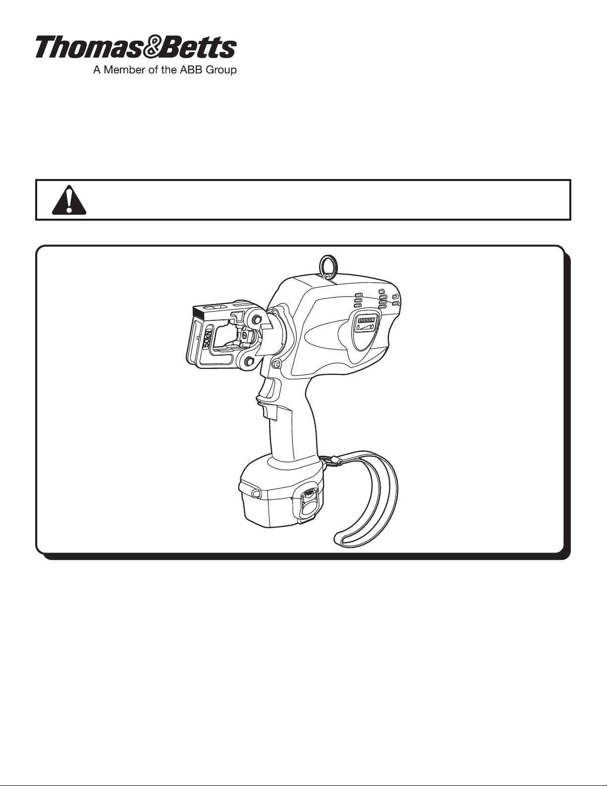
1.0 GENERAL CHARACTERISTICS
BATTERY OPERATED
HYDRAULIC CRIMPING TOOL
This “BPLT62BSCR” hydraulic tool is powered by 14.4 V
DC Ni-MH battery. The tool is well balanced for optimum
control, quiet operation, very little vibration and lightweight
construction enabling the operator to hold the tool in
one hand while positioning the connector with the other
hand. The tool has a two speed operation which provides
automatic shifting from a rapid ram advance mode to
a slow powerful crimping mode. The residual battery
capacity level is automatically displayed after every cycle.
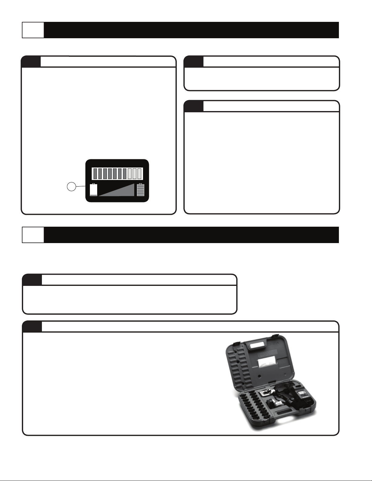
BPLT62BSCR Includes the following:
• Battery • Wrist Strap • Tool Strap
• Spare Battery • Battery Charger • Carrying Case
BPLT62500BSCR Includes the following:
• Battery • Wrist Strap • Tool Strap
• Spare Battery • Battery Charger • Die Set
• Carrying Case
Suitable for installing electric compression connectors for
conductors from 8 AWG up to 500 MCM CU, 350 MCM AL.
Crimping Force Nominal................................6 Tons
Rated Operating Pressure..........................8600 psi
Dimensions:
Length..............................................................11.7”
Width..................................................................3.7”
Height...............................................................11.9”
Weight (with battery)......................................8.8 lbs
Motor.........................................................14.4V DC
Battery - direct current.........14.4 V - 3.0 Ah Ni-MH
Oil Recommended..................AGIP ARNICA 32 or
SHELL TELLUS TX32 or equivalent
Safety...............the tool is provided with a
maximum pressure relief safety valve.
(Directive 2006/42/EC, annexe 1, point 1.7.4.2 letter u)
The weighted continuous acoustic pressure level
equivalent
A at the work place LPA is equal to...............
75 dB (A)
The maximum value of the weighted acoustic
displacement pressure
C at the work place LpCPeak is....................
<130 dB (C)
The acoustic power level emitted by the machine
LWA is equal to............................................85,3 dB (A)
(Directive 2006/42/EC, annexe 1, point 2.2.1.1)
Test carried out in compliance with the indications
contained in UNI ENV 25349 and UNI EN 28662
part 1st Standards, and under operating conditions
much more severe than those normally found,
certify that the weighted root mean square in
frequency of the acceleration the upper limbs are
exposed to for each biodynamic reference axis
does not exceed 2.5 m/sec2.
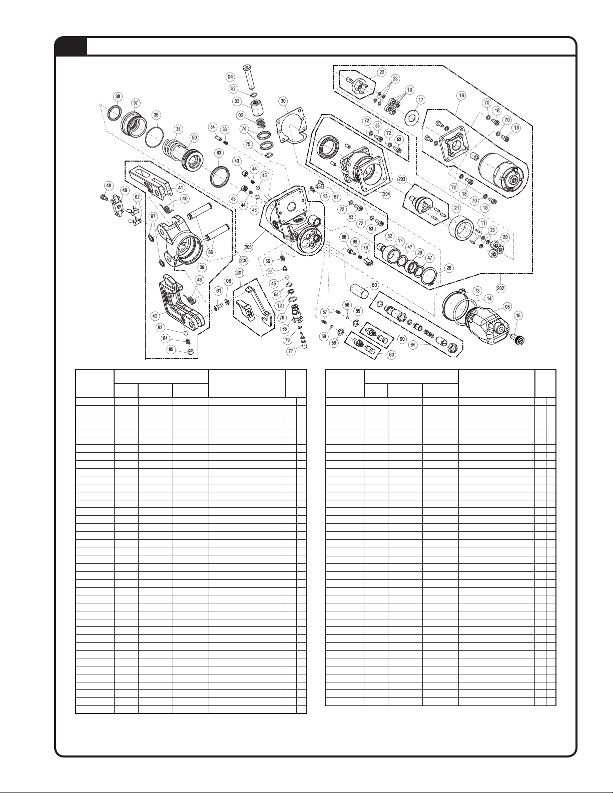
1.5 OVERALL VIEW
1.1
APPLICATION RANGE
1.2
10 Operating Button 201 Pressure Release Lever
14 Wrisp Strap HHead
15 Battery Capacity Indicator RRing for Shoulder Strap
16 Battery TShoulder Strap
RISK DUE TO VIBRATION
ACOUSTIC NOISE
1.3
1.4
Fig. 1
TA03943 D Page 2 of 8
WARNING
1. BEFORE USING THE TOOL, CAREFULLY READ
INSTRUCTIONS IN THIS MANUAL.
2. WHEN OPERATING THE TOOL, KEEP HANDS AND OTHER
BODY PARTS AWAY FROM THE DANGER ZONE.
3. DO NOT USE IN WATER OR IN THE RAIN.
4. ALWAYS ENSURE CORRECT LATCHING AND
SECURENESS OF THE TOOL HEAD.
5. DO NOT SHORT THE BATTERIES.
6. ALWAYS RECYCLE THE BATTERIES.
7. DO NOT DISCARD BATTERIES INTO DOMESTIC REFUSE
OR WASTE DISPOSAL.

42
83
62
49
41
10
201
TA03943 D Page 3 of 8
2.0 INSTRUCTIONS FOR USE
The tool can be easily carried using either the handle or
shoulder strap (T) attached to the rings (R), see Fig. 1 on
page 2.
With the tool at rest, proceed as follows:
•Select the appropriate die set for the connector.
(Ref: Check Thomas & Betts instruction sheet for the
connector and make sure color code of die matches
color code of connector.)
•
Open the latch (41) and release the upper die holder (42).
• Insert one die into the upper die holder (42) and one
die into the lower die support (49).
•Close the latch (41).
• Insert the conductor in connector.
•Position the connector between the dies and ensure
the correct location of the crimp. (See connectors
instruction sheet for number of crimps.)
Ensure that the latch and upper die holder are fully
secured, otherwise damage may occur during tool
operation.
PREPARATION (Refer to Figs. 1, 2 & 3)
2.1
•Press the operating button (10) to activate the
motor-pump and advance the lower die. To halt the
advancement, release the operating button (10) and the
motor will stop.
Make sure the dies are exactly positioned on desired
crimp point, otherwise re-open dies following instructions
as per Step 2.5 and position the connector again.
DIE ADVANCEMENT (Refer to Fig. 3)
2.2
Fig. 2
COMPRESSION
2.3
•By keeping operating button (10) pressed, the motor
continues to operate: the ram will gradually move
forward until the two dies touch.
• It is recommended to continue pumping until the
maximum pressure relief valve is activated and a
“click” is heard.
•The motor will continue to operate after the maximum
pressure relief valve has activated. No further crimping
force is applied, the oil is bypassed and returned to
reservoir.
•For ease of operation, the tool head can be rotated
through 180º, allowing the operator to work in the most
comfortable position.
HEAD ROTATION
2.4
WARNING
Do not attempt to rotate the head when the hydraulic
circuit is pressurized.
•By pressing the pressure release lever (201) located
below operating button (10), the ram will retract and
open the dies.
RELEASE OF DIES
2.5
Fig. 3
WARNING
When operating the tool, keep hands and other body parts
away from the danger zone.
DANGER
DO NOT USE THIS TOOL ON OR
NEAR ENERGIZED CONDUCTORS
WITHOUT PROPER PERSONAL
PROTECTIVE EQUIPMENT.
FAILURE TO OBSERVE THIS
WARNING COULD RESULT IN SEVERE
INJURY OR DEATH.

TA03943 D Page 4 of 8
3.0 BATTERY USE
The tool is supplied with the batteries completely discharged; before use, fully charge the batteries using the charger supplied.
USING THE BATTERY CHARGER
3.2
Carefully follow the instructions in the battery
charger manual.
In order to use the batteries correctly, please follow
these rules:
• Use the battery until the automatic residual energy
display still has 1-2 LEDs showing: this means the
battery is almost completely discharged and no loss
in the life of the battery has been produced.
•Be particularly careful when charging a new battery
the first 2-3 times in order to maximize the available
energy level.
•Allow the battery to cool down to ambient
temperature prior to recharging.
•Rest the battery charger for at least 15 minutes
between charges.
4.0 MAINTENANCE
The tool is robust, completely sealed, and requires very little daily maintenance. Compliance with the following points,
should help to maintain the optimum performance of the tool:
THOROUGH CLEANING
4.1
Dust, sand and dirt are a danger for any hydraulic device. Every day, after use,
the tool must be wiped with a clean cloth taking care to remove any residue,
especially close to pivots and moveable parts. Protect the tool from rain and
moisture. Water will damage the tool and battery.
STORAGE
(Refer to Fig 5)
4.2
When not in use, the tool should be stored and
transported in the plastic case, to prevent damage. This
case is suitable for storing the tool, the accessories
and up to 21 die sets and pre-prepared compression
connectors.
Plastic Case: size 24.1x16.2x5.1 inches, (543x412x130
mm) weighs 5 lbs. (2,3 kg).
Fig. 5
%
15
BATTERY STATUS (Refer to Fig. 4)
3.1
Fig. 4
•After releasing the operating button, the residual
battery capacity is automatically displayed for 5
seconds on the indicator (15).
The number of LEDs illuminated indicates
the residual capacity:
10 LEDs illuminated: Fully Charged
5 LEDs illuminated: 50% capacity
1 LED illuminated: Minimum charge
When replacing the battery, press the two points
marked with the word “PUSH” at the same time, remove
the flat battery from its housing and insert the new one.
USING BATTERIES
3.3

5.0 SPARE PARTS LIST
BPLT62BSCR
Spare parts kit code no. 6000057 includes items marked “K” in table, available on
request.
When ordering spare parts always specify the following:
• Code number of item
• Name of item
• Type of tool
• Tool serial number
The Guarantee is void if parts are not Thomas & Betts original replacement parts.
For parts or service, contact the tool service center at 1-800-284-TOOL (8665).
TA03943 D Page 5 of 8

01
05
11 10
09
07 See TABLE 2
Tool Serial Number
02
04
05
16
xxxxxx
13
13 03
08
13
17
15
04
14
01
03 04
TABLE 1
5.1
Code Nº ITEMS DESCRIPTION QTY
Main 1st Sub 2nd Sub
6000512 01 – – Electric Circuit+Shells 1
6000658 01 01 – Right + Left Shell 1
6900646 01 03 – Screw 2,2x6,5 2
6760144 01 04 – Pin D.3x22 2
6000240 01 05 – Compl. Electr. Circuit 1
6000649 02 – – Screw 2,2 x 4,5 2
6900655 03 – – Screw 3,5x38 3
6000304 04 – – Ring 2
6040427 05 – – Ring 1
6000544 07 – – Mechanical Group 1
6900650 08 – – Screw 1
6760149 09 – – Pin d.3x16 1
6000237 10 – – Button 1
6520531 11 – – Spring 2
6900651 13 ––Screw 3,5x22 8
6000447 14 – – Wrist 1
6232095 15 – – Label Strap 1
8502001 16 – – Battery 1
6232497 17 – – Label Strap 1
TA03943 D Page 6 of 8

16
22
203
202
60
200
39
40
41
42
46
83
84
85
86
87
02
03
04
08
12
13
14
30
33
34
35
36
37
38
43
43
44
44
45
45
45
48
49
50
52
53
53
53
53
54
55
56
57
58
58
59
59
61
62
63
65
67
68
69
72
72
72
72
73
74
75
76
77
78
79
80
11
17
18
18
18
18
19
20
21
23
23
26
29
32
47
47
70
70
70
70
71
205
204
60
201
64
05
15
TABLE 2 (Item 07 from table 1)
5.2
Code Nº ITEMS DESCRIPTION QTY
Main 1st Sub 2nd Sub
6520532 02 – – Spring 1 –
6620113 03 – – H.S. RAM 1 –
6620109 04 – – Pumping Ram 1 –
6720073 05 – – Reservoir 1 –
6000330 08 – – Spacer 1 –
6040080 12 – – Back-Up Ring 1 K
6360022 13 – – O-Ring 1 K
6360260 14 – – O-Ring 1 K
6800040 15 – – Cap 1 –
6361999 30 – – Seal 1 K
6520601 33 – – Spring 1 K
6760230 34 – – Pin 1 –
6520030 35 – – Spring 1 –
6361900 36 – – O-Ring 1 –
6040556 37 – – Ram Guide Ring 1 –
6362020 38 – – Seal 1 –
6340590 43 – – Grub Screw 2
6520200 44 – – Spring 2 K
6740120 45 – – Ball 3 K
6900629 48 – – Screw 1 –
6780252 49 – – Die Support 1 –
6620490 50 – – Ram – –
6360161 52 – – O-Ring 1 K
6900090 53 – – Screw 4
6360140 54 – – O-Ring 1 K
6600100 55 – – Dowel 1
6520520 56 – – Spring 1 K
6520160 57 – – Spring 2 K
6740100 58 – – Ball 2 K
6641020 59 – – Washer 2 K
6900601 60 – – Suct. Screw 2 –
6900181 61 – – Screw M4x10 1 –
6520382 62 – – Die Stop Spring 2 –
6362098 63 – – Seal 1 –
6895049 64 – – Compl. Valve 1 –
6900640 65 – – Press. Release Screw 1 –
6900306 67 – – Screw 1 –
6635011 68 – – Pin 1 K
6520861 69 – – Spring 1 K
6640205 72 – – Washer 4 K
Code Nº ITEMS DESCRIPTION QTY
Main 1st Sub 2nd Sub
6250084 73 – – Tie 1 –
6362021 74 – – Seal 2 K
6362007 75 – – Seal 1 K
6340720 76 – – Grub Screw 1 –
6020020 77 – – Pin 1 –
6361881 78 – – O-Ring 1 K
6360120 79 – – O-Ring 1 K
6000385 80 – – Bush 1 –
6860012 200 – – Compl. Head 1 –
6780150 200 39 – Head Support 1 –
6520482 200 40 – Spring 1 –
6370270 200 41 – Latch 1 –
6780133 200 42 – Upper Die Holder 1 –
6520403 200 45 – Spring 1 –
6740020 200 83 – Ball 1 –
6520942 200 84 – Spring 1 –
6340138 200 85 – Grub Screw 1 –
6560370 200 86 – Pin 2 –
6040725 200 87 – Circlip 2 –
6440117 201 – – Pres. Release Lever 1 –
6000523 202 – – Complete Housing 1 –
6760001 202 11 – Pin 2 –
6000310 202 16 – Comp. Motor 1 –
6000328 202 17 – Washer 1 –
6900181 202 18 – Screw 4 –
6000364 202 19 – Gear 4 –
6000363 202 20 – Gear 3 –
6000323 202 21 – Gear 1 –
6000196 202 22 – Gear 1 –
6000315 202 23 – Washer 7 –
6700520 202 26 – Circlip 1 –
6000392 202 29 – Bearing 1 –
6040682 202 32 – Ring 1 –
6220198 202 47 – Spacer 2 –
6640205 202 70 – Washer 4 –
6040686 202 71 – Ring 1 –
6000336 202 203 – Eccentric 1 –
6000525 202 204 – Housing 1 –
6160054 205 – – Body 1 –
TA03943 D Page 7 of 8

TA03943 D Page 8 of 8©2013 Thomas & Betts. All Rights Reserved.
Thomas & Betts Corporation
Memphis, Tennessee
www.tnb.com
WARRANTY: Thomas & Betts sells this product with the understanding that the user will perform all necessary tests to determine the suitability
of this product for the user’s intended application. Thomas & Betts warrants that this product will be free from defects in materials and
workmanship for the period stated on the enclosed warranty card. Upon prompt notication of any warranted defect, Thomas & Betts will, at
its option, repair or replace the defective product. Misuse, misapplication or modication of Thomas & Betts products immediately voids all
warranties.
Limitations and Exclusions: THE ABOVE WARRANTY IS THE SOLE WARRANTY CONCERNING THIS PRODUCT, AND IS IN LIEU OF ALL
OTHER WARRANTIES EXPRESS OR IMPLIED, INCLUDING BUT NOT LIMITED TO ANY IMPLIED WARRANTY OF MERCHANTABILITY
OR FITNESS FOR A PARTICULAR PURPOSE, WHICH ARE SPECIFICALLY DISCLAIMED. LIABILITY FOR BREACH OF THE ABOVE
WARRANTY IS LIMITED TO COST OF REPAIR OR REPLACEMENT OF THE PRODUCT, AND UNDER NO CIRCUMSTANCES WILL
THOMAS & BETTS BE LIABLE FOR ANY INDIRECT, SPECIAL, INCIDENTAL OR CONSEQUENTIAL DAMAGES.
For parts or service, contact the tool service center at 1-800-284-TOOL (8665).
This manual suits for next models
1
Table of contents
Other ABB Crimping Tools manuals